

PB Heat DE User Manual
DE
Boilers
Series
Gas
Installation,
Operation &
Maintenance
Manual

ii
USING THIS MANUAL 1
A. INSTALLATION SEQUENCE . . . . . . . . . . . . .1
B. SPECIAL ATTENTION BOXES . . . . . . . . . . . .1
1. PREINSTALLATION 2
A. ACCESSIBILITY CLEARANCES . . . . . . . . . . .2
B. CLEARANCE FROM COMBUSTIBLE
CONSTRUCTION . . . . . . . . . . . . . . . . . . . . . .2
C. AIR FOR COMBUSTION AND
VENTILATION . . . . . . . . . . . . . . . . . . . . . . . . .2
D. INSTALLATION SURVEY . . . . . . . . . . . . . . . .5
E. PLANNING THE LAYOUT . . . . . . . . . . . . . . . .5
2. BOILER SET-UP 6
3. WATER PIPING AND CONTROLS 7
A. BOILER SUPPLY AND RETURN . . . . . . . . . . .7
B. SAFETY RELIEF VALVE . . . . . . . . . . . . . . . . .8
C. PIPING FOR ZONED SYSTEMS . . . . . . . . . . .9
D. EXPANSION TANK . . . . . . . . . . . . . . . . . . . .10
E. INDIRECT-FIRED WATER HEATER . . . . . . .10
F. FREEZE PROTECTION . . . . . . . . . . . . . . . . .10
4. VENTING 11
A. GENERAL . . . . . . . . . . . . . . . . . . . . . . . . . . .11
B. CHIMNEY VENTING . . . . . . . . . . . . . . . . . . .11
C. DIRECT EXHAUST
HORIZONTAL VENTING- . . . . . . . . . . . . . . .11
D. DIRECT EXHAUST
VERTICAL VENTING . . . . . . . . . . . . . . . . . .14
E. BOILER REMOVAL FROM
COMMON VENTING SYSTEM . . . . . . . . . .15
5. GAS PIPING 16
6. ELECTRICAL 18
A. WIRING . . . . . . . . . . . . . . . . . . . . . . . . . . . . .18
B. ZONED SYSTEM WIRING . . . . . . . . . . . . . .18
C. CONTROLS . . . . . . . . . . . . . . . . . . . . . . . . . .18
D. SEQUENCE OF OPERATION . . . . . . . . . . . .19
7. START-UP PROCEDURES 22
A. COMPLETING THE INSTALLATION . . . . . . .22
B. CONTROL DESCRIPTIONS . . . . . . . . . . . . .25
C. ADJUSTMENT OF GAS PRESSURE
REGULATOR . . . . . . . . . . . . . . . . . . . . . . . . .25
D. CHECKING BURNER INPUT . . . . . . . . . . . . .25
E. CHECK-OUT PROCEDURE . . . . . . . . . . . . . .26
8. TROUBLESHOOTING 28
A. SHUT-DOWN CAUSED BY PILOT OUTAGE,
PRESSURE SWITCH OR FLAME ROLL-OUT
SAFETY SHUT-OFF SWITCH . . . . . . . . . . . .28
B. TROUBLESHOOTING GUIDES . . . . . . . . . .28
C. MEASURING SUCTION PRESSURE . . . . . .28
9. MAINTENANCE 32
A. GENERAL . . . . . . . . . . . . . . . . . . . . . . . . . . .33
B. DAILY (WITH BOILER IN USE) . . . . . . . . . . .33
C. WEEKLY (WITH BOILER IN USE) . . . . . . . . .33
D. MONTHLY (WITH BOILER IN USE) . . . . . . .33
E. ANNUALLY (BEFORE START OF HEATING
SEASON) . . . . . . . . . . . . . . . . . . . . . . . . . . .34
10. BOILER DIMENSIONS & RATINGS 35
11. REPAIR PARTS 36
A. BLOCK/BASE/FLOOR PAN
JACKET/FLUE COLLECTOR . . . . . . . . . . . . .36
B. BASE/BURNERS/MANIFOLD . . . . . . . . . . . .37
TABLE OF CONTENTS
TABLE OF CONTENTS
1
A. INSTALLATION SEQUENCE
Follow the installation instructions provided in this
manual in the order shown. The order of these
instructions has been set in order to provide the installer
with a logical sequence of steps that will minimize
potential interferences and maximize safety during
boiler installation.
B. SPECIAL ATTENTION BOXES
Throughout this manual you will see special attention
boxes intended to supplement the instructions and make
special notice of potential hazards. These categories
mean, in the judgment of PB Heat, LLC:
Indicates special attention is needed, but not directly
related to potential personal injury or property
damage.
NOTICE
Indicates a condition or hazard which will or can
cause minor personal injury or property damage.
CAUTION
DANGER
Indicates a condition or hazard which will cause
severe personal injury, death or major property
damage.
USING THIS MANUAL
USING THIS MANUAL
Indicates a condition or hazard which may cause
severe personal injury, death or major property
damage.
WARNING
2
A. ACCESSIBILITY CLEARANCES
Install boiler not less than 24″ (610 mm) between the left
side, top, and front of the boiler and adjacent wall or
other appliance, when access is required for servicing.
B. CLEARANCE FROM COMBUSTIBLE
CONSTRUCTION
The design of this boiler is certified for closet installation
with the following clearances:
1. 6″ (152 mm) between sides, rear and front and
combustible construction.
2. 24″ (610 mm)between top of jacket and
combustible construction.
3. 2″ (51 mm) between vent pipe and combustible
construction.
C. AIR FOR COMBUSTION AND
VENTILATION
1. Adequate combustion air and ventilation air must be
provided in accordance with section 5.3, Air for
Combustion and Ventilation, of the National Fuel
Gas Code, ANSI Z223.1/NFPA 54, or Sections 7.2,
7.3 or 7.4 of CAN/CSA B149.1, Natural Gas and
Propane Installation Code or applicable provisions of
the local building code. Subsections 2 through 8 as
follows are based on the National Fuel Gas Code
requirements.
2. Requir
ed Combustion Air Volume: The total required
volume of indoor air is to be the sum of the required
volumes for all appliances located within the space.
Rooms communicating directly with the space in
which the appliances are installed and through
combustion air openings sized as indicated in
Subsection 3 are considered part of the required
volume. The required volume of indoor air is to be
determined by one of two methods.
a. Standard Method: The minimum required
volume of indoor air (room volume) shall be 50
cubic feet per 1000 BTU/Hr (4.8 m3/kW). This
method is to be used if the air infiltration rate is
unknown or if the rate of air infiltration is known
to be greater than 0.6 air changes per hour. As
an option, this method may be used if the air
infiltration rate is known to be between 0.6 and
0.4 air changes per hour. If the air infiltration rate
is known to be below 0.4 then the Known Air
Infiltration Rate Method must be used. If the
building in which this appliance is to be installed
is unusually tight, we recommend that the air
infiltration rate be determined.
b. Known Air Infiltration Rate Method: Where
the air infiltration rate of a structure is known, the
minimum required volume of indoor air for the
Series DE Boiler and other fan assisted
appliances shall be determined as follows:
PREINSTALLATION
1. PREINSTALLATION
Read carefully, study these instructions before beginning work.
This boiler must be installed by a qualified contractor.
The boiler warranty can be voided if the boiler is not installed, maintained and serviced correctly.
The equipment must be installed in accordance with those installation requirements of the authority having
jurisdiction or, in the absence of such requirements, to the current edition of the
National Fuel Gas Code
, ANSI
Z223.1/NFPA 54 and/or CAN/CSA B149.1,
Natural Gas and Propane Installation Code
.
Where required by the authority having jurisdiction, the installation must conform to
American Society of
Mechanical Engineers Safety Code for Controls and Safety Devices for Automatically Fired Boilers,
ANSI/ASME CSD-1.
NOTICE
Do not install this boiler on carpeting. Boiler
installation on carpeting is a fire hazard. Install this
boiler on non-combustible flooring or use a
combustible floor pan to install this boiler on other
non-carpeted flooring.
DANGER
Do not install this boiler on combustible flooring
unless it is installed on a special combustible floor
pan provided by PB Heat, LLC. Boiler installation on
combustible flooring without the special pan is a fire
hazard.
To order combustible floor pan, use the 5-digit stock
codes listed in Section 11 of this manual.
DANGER
15 ft
3
I
fan
ACH 1000
Btu
/
hr
Required Volume
fan
=
⎛
⎜
⎝
⎛
⎜
⎝
3
where:
I
fan
= Input of the fan assisted appliances in
Btu/hr
ACH = air change per hour (percent of the
volume of the space exchanged per
hour, expressed as a decimal)
For appliances other than fan assisted, calculate
the required volume of air using the following
equation:
I
other
= Input of appliances other than fan
assisted in Btu/hr
Note: These calculations are not to be used for
infiltration rates greater than 0.60 ACH.
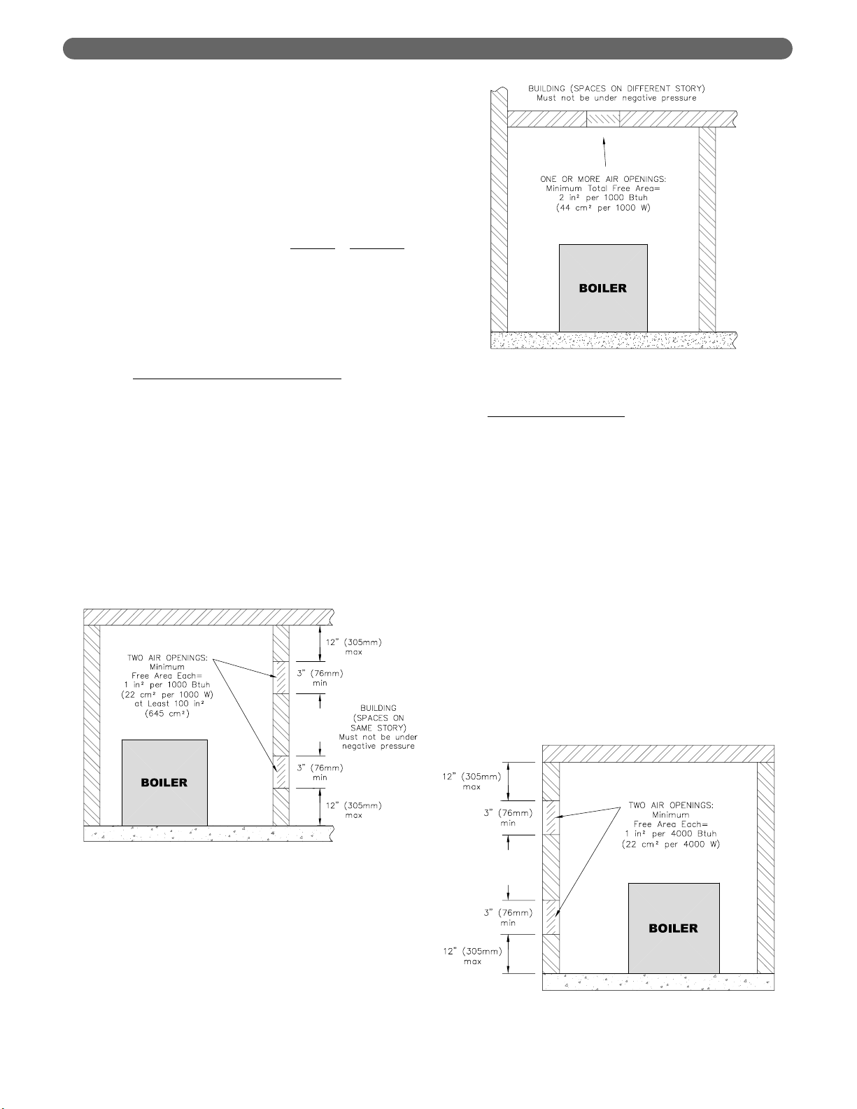
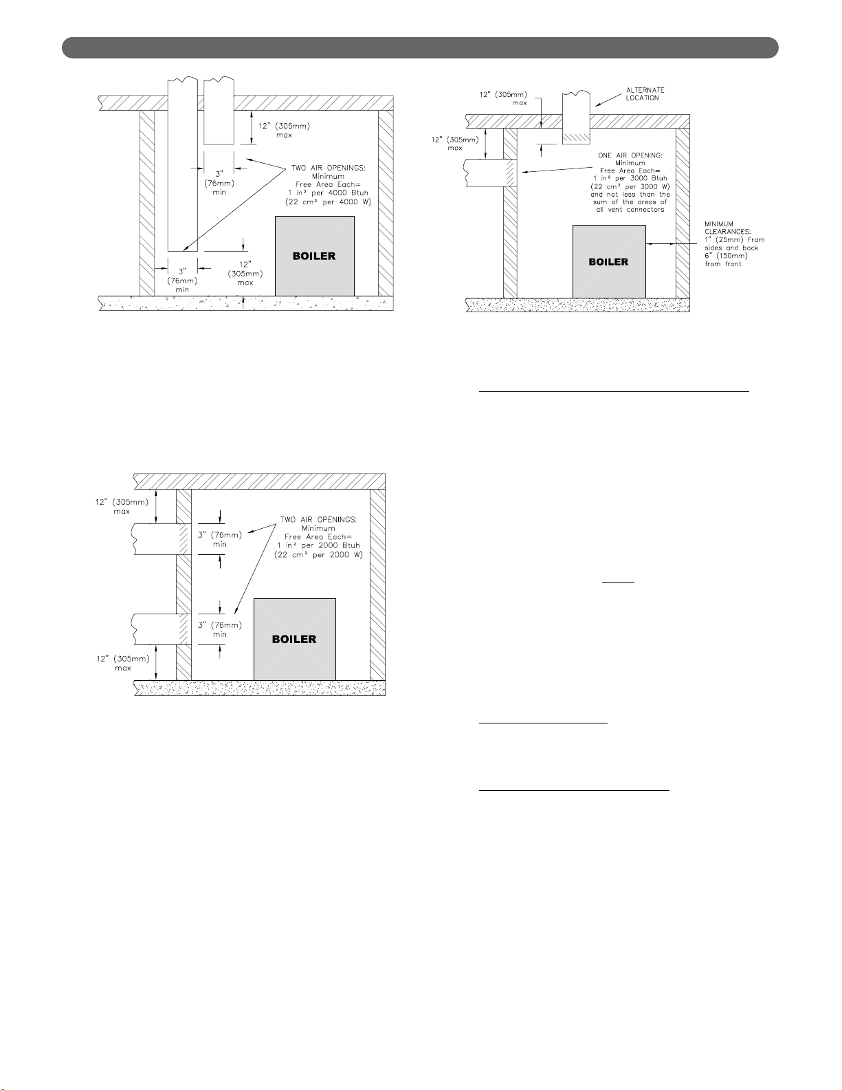
3. Indoor Air Opening Size and Location:
Openings
connecting indoor spaces shall be sized and located
as follows:
a. Combining spaces on the same floor:
Provide two permanent openings communicating
with additional spaces that have a minimum free
area of 1 in
2
per 1000 Btu/hr (22 cm2per 1000 W)
of the total input rating of all gas fired equipment
but not less than 100 in
2
(645 cm2). One
opening is to begin within 12 inches (305 mm)
from the top of the space and the other is to
begin within 12 inches (305 mm) from the floor.
The minimum dimension of either of these
openings shall be 3 inches (76 mm). See Figure
1.1 for an illustration of this arrangement.
b. Combining spaces on different floors:
Provide one or more permanent openings
communicating with additional spaces that have
a total minimum free area of 2 in
2
per 1000
Btu/hr (44 cm
2
per 1000 W) of total input rating
of all equipment. See Figure 1.2 for an
illustration of this arrangement.
4. Outdoor Combustion Air:
Outdoor combustion air is
to be provided through one or two permanent
openings. The minimum dimension of these air
openings is 3 inches (76 mm).
a. Two Permanent Opening Method: Provide
two permanent openings. One opening is to
begin within 12 inches (305 mm) of the top of
the space and the other is to begin within 12
inches (305 mm) of the floor. The openings are
to communicate directly or by ducts with the
outdoors or with spaces that freely communicate
with the outdoors. The size of the openings shall
be determined as follows:
i. Where communicating directly or through
vertical ducts with the outdoors each opening
shall have a minimum free area of 1 in
2
per
4000 Btu/hr (22 cm
2
per 4000 W) of total
input rating for all equipment in the space.
See Figure 1.3 for openings directly
communicating with the outdoors or Figure
1.4 for openings connected by ducts to the
outdoors.
PREINSTALLATION
Figure 1.1: Air Openings – All Air from Indoors
on the Same Floor
Figure 1.2: Air Openings – All Air from Indoors
on Different Floors
21 ft
3
I
other
ACH 1000
Btu
/
hr
Required Volume
other
=
⎛
⎜
⎝
⎛
⎜
⎝
Figure 1.3: Air Openings – All Air Directly from
Outdoors
4
ii. Where communicating with the outdoors
through horizontal ducts, each opening shall
have a minimum free area of 1 in
2
per 2000
Btu/hr (22 cm
2
per 2000 W) of total rated
input for all appliances in the space. See
Figure 1.5.
b. One Permanent Opening Method: Provide
one permanent opening beginning within 12
inches (305 mm) of the top of the space. The
opening shall communicate directly with the
outdoors, communicate through a vertical or
horizontal duct, or communicate with a space
that freely communicates with the outdoors. The
openings shall have a minimum free area of 1 in
2
per 3000 Btu/hr of total rated input for all
appliances in the space and not less than the
sum of the cross-sectional areas of all vent
connectors in the space. The gas fired equipment
shall have clearances of at least 1 inch (25 mm)
from the sides and back and 6 inches (150 mm)
from the front of the appliance. See Figure 1.6
for this arrangement.
5. Combination Indoor and Outdoor Combustion Air:
If the required volume of indoor air exceeds the
available indoor air volume, outdoor air openings or
ducts may be used to supplement the available
indoor air provided:
a. The size and location of the indoor openings
comply with Subsection 3.
b. The outdoor openings are to be located in
accordance with Subsection 4.
c. The size of the outdoor openings are to be sized
as follows:
where:
A
req
= minimum area of outdoor openings.
A
full
= full size of outdoor openings calculated
in accordance with Subsection 4.
V
avail
= available indoor air volume
V
req
= required indoor air volume
6. Engineer
ed Installations: Engineered combustion air
installations shall provide an adequate supply of
combustion, ventilation, and dilution air and shall be
approved by the authority having jurisdiction.
7. Mechanical Combustion Air Supply
:
a. In installations where all combustion air is
provided by a mechanical air supply system, the
combustion air shall be supplied from the
outdoors at the minimum rate of 0.35 ft
3
/min per
1000 Btu/hr (0.034 m
3
/min per 1000 W) of the
total rated input of all appliances in the space.
b. In installations where exhaust fans are installed,
additional air shall be provided to replace the
exhaust air.
V
avail
1 –
V
req
A
req
= A
full
x
⎛
⎜
⎝
⎛
⎜
⎝
Figure 1.5: Air Openings – All Air from Outdoors
through Horizontal Ducts
Figure 1.6: Air Openings – All Air from Outdoors
through One Opening
Figure 1.4: Air Openings – All Air from Outdoors
through Vertical Ducts
PREINSTALLATION
5
c. Each of the appliances served shall be
interlocked to the mechanical air supply to
prevent main burner operation where the
mechanical air supply system is not in operation.
d. In buildings where the combustion air is provided
by the mechanical ventilation system, the system
shall provide the specified combustion air rate in
addition to the required ventilation air.
8. Louvers & Grills:
a. The required size of openings for combustion,
ventilation, and dilution air shall be based on the
net free area of each opening.
i. Where the free area through a louver or grille
is known, it shall be used in calculating the
opening size required to provide the free area
specified.
ii. Where the free area through a louver or grille
is not known, it shall be assumed that wooden
louvers will have 25% free area and metal
louvers and grilles will have 75% free area.
iii. Nonmotorized dampers shall be fixed in the
open position.
b. Motorized dampers shall be interlocked with the
equipment so that they are proven in the full
open position prior to ignition and during
operation of the main burner.
i. The interlock shall prevent the main burner
from igniting if the damper fails to open
during burner startup.
ii. The interlock shall shut down the burner if
the damper closes during burner operation.
9. Combustion Air Ducts
a. Ducts shall be constructed of galvanized steel or
an equivalent corrosion- resistant material.
b. Ducts shall terminate in an unobstructed space,
allowing free movement of combustion air to the
appliances.
c. Ducts shall serve a single space.
d. Ducts shall not serve both upper and lower
combustion air openings where both such
openings are used. The separation between ducts
serving upper and lower combustion air
openings shall be maintained to the source of
combustion air.
e. Ducts shall not be screened where terminating in
an attic space.
f. Horizontal upper combustion air ducts shall not
slope downward toward the source of the
combustion air.
g. The remaining space surrounding a chimney
liner, gas vent, special gas vent, or plastic piping
installed within a masonry, metal, or factory built
chimney shall not be used to supply combustion
air.
h. Combustion air intake openings located on the
exterior of buildings shall have the lowest side of
the combustion air intake opening at least 12
inches (305 mm) above grade.
D. INSTALLATION SURVEY
For new and existing installations, a Water Installation
Survey is available from PB Heat, LLC. The survey will
provide information on how a hot water boiler works
with your specific system and will provide an overview
of hot water system operation in general.
You can also use this survey to locate system problems
which will have to be corrected. To obtain copies of the
Water Installation Survey, contact your Peerless
representative or download it from PeerlessBoilers.com.
E. PLANNING THE LAYOUT
Prepare sketches and notes of the layout to minimize the
possibility of interferences with new or existing
equipment, piping, venting and wiring.
Liquefied Petroleum (LP) is heavier than air and may
collect or “pool” in a low area in the event of a leak
from defective equipment. This gas may then ignite,
resulting in a fire or explosion.
WARNING
PREINSTALLATION

6
BOILER SET-UP
1. Provide a sound, level foundation. Locate boiler as
near to the chimney or outside wall as possible and
centralized with respect to the heating system.
2. Locate boiler in front of installation position before
removing crate.
3. If using combustible floor pan, position pan on
foundation or flooring.
4. Separate the wood shipping pallet from the boiler
base by removing two (2) hold-down bolts at each
end of the boiler base.
5. Move boiler into final position. If using combustible
floor pan, install boiler on pan as outlined in the
instructions included with the pan.
2. BOILER SET-UP
7
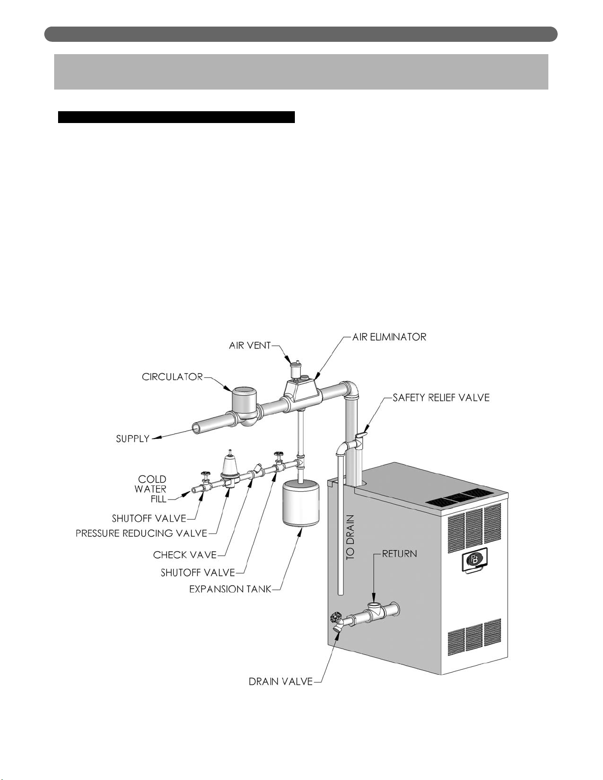
A. BOILER SUPPLY AND RETURN
1. Size the supply and return to suit the system. A
typical piping arrangement is shown in Figure 3.1.
Refer also to the I=B=R Guide to Residential
Hydronic Heating Installation/Design and the PB
Heat, LLC Water Survey for additional guidance
during water piping installation.
2. Return Piping:
a. Pipe the outlet connection of the circulator to a
tee, provided with a drain valve, at the 1-1/4
NPT return tapping near the bottom of the left
section. Pipe the return to the inlet connection of
the circulator.
3. Supply Piping:
Pipe the supply to the 1-1/2 NPT supply tapping at
the top of the boiler.
4. When system return water temperature will be below
130°F (54°C), pipe the boiler with a bypass
arrangement to blend the system return and hot
supply to obtain at least 130°F (54°C) entering the
boiler. For more information on bypass piping,
consult the PB Heat, LLC Water Survey.
5. If desired, install the circulator in the alternate
location shown in Figure 3.1. Consult the PB Heat,
LLC Water Survey for more information on
circulator location.
3. WATER PIPING AND CONTROLS
Figure 3.1: Supply and Return Piping
WATER PIPING AND CONTROLS
8
6. Install this boiler so that the gas ignition system
components are protected from water (dripping,
spraying, etc.) during appliance operation and
service (circulator replacement, condensate trap,
control replacements, etc.).
7. If this boiler and distribution system is used in
conjunction with a refrigeration system, pipe the
chilled medium in parallel with the boiler and install
the proper valve to prevent the chilled medium from
entering the boiler. A drawing illustrating this hookup is provided in Figure 3.2.
8. When the boiler is connected to heating coils located
in air handling units where they may be exposed to
refrigerated air circulation, install flow control valves
or other automatic means to prevent gravity
circulation of the boiler water during the cooling
cycle.
9. If this boiler is installed above radiation level,
provide a low water cutoff device, either as a part of
the boiler or at the time of boiler installation.
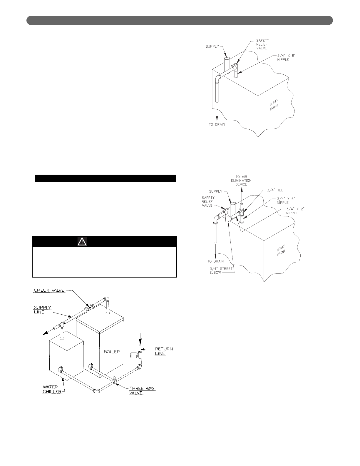
B. SAFETY RELIEF VALVE
1. Locate safety relief valve and fittings in bag
assembly.
2. If air elimination is not required at the safety relief
valve tapping, install valve and piping as shown in
Figure 3.3.
3. For air elimination at the safety relief valve tapping,
install valve and piping as shown in Figure 3.4.
Pipe the discharge of safety relief valve to prevent
injury in the event of pressure relief. Pipe the
discharge to a drain. Provide piping that is the same
size as the safety relief valve outlet.
CAUTION
Figure 3.4: Safety Relief Valve Hook-Up with
Air Elimination
Figure 3.3: Safety Relief Valve Hook-Up
Installation with Air Elimination in
System Piping
Figure 3.2: Parallel Hook-up with Water Chiller
WATER PIPING AND CONTROLS
9
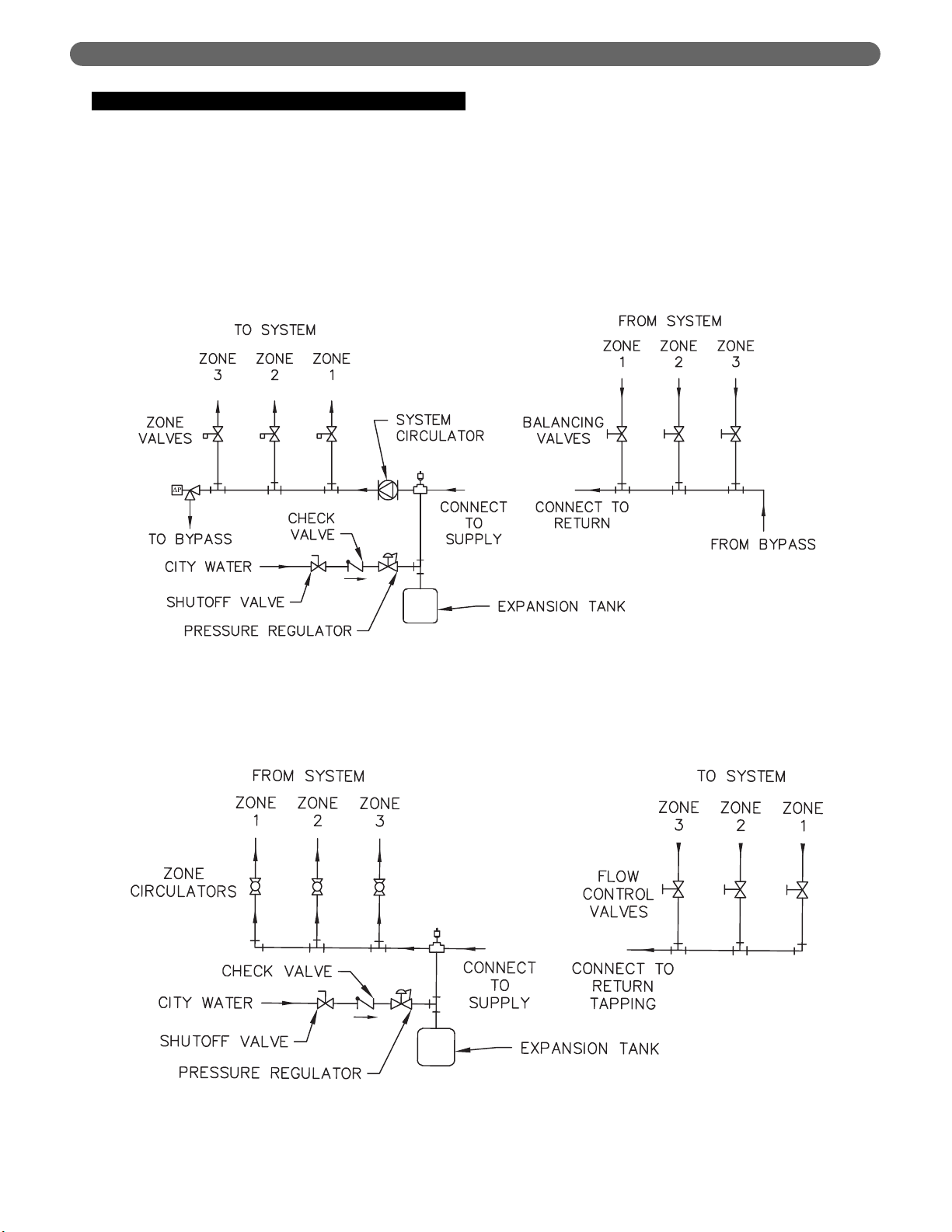
C. PIPING FOR ZONED SYSTEMS
1. See Figures 3.5 and 3.6 for basic zoned system
layouts.
2. Run each zone pipe down then up to zone to
prevent air accumulation in piping.
3. If required, provide means to isolate and drain each
zone separately.
Figure 3.5: Zone Piping with Zone Valves
Figure 3.6: Zone Piping with Circulators
WATER PIPING AND CONTROLS

10
D. EXPANSION TANK
1. Consult the tank manufacturer’s instructions for
specific information relating to tank installation. Size
the expansion tank for the required system volume
and capacity. See Table 10.2 in Section 10 for boiler
water capacity.
2. Expansion tanks are available with built-in fill valves
and check valves for reducing supply water pressure
and maintaining minimum system pressure. Check
the design features of the tank and provide valves as
necessary.
Refer back to Figure 3.1 for typical expansion tank piping.
E. INDIRECT-FIRED WATER HEATER
If the boiler is to be used in conjunction with an indirectfired water heater, refer to Figure 3.7 for typical piping.
Follow the instructions provided by the water heater
manufacturer. Pipe the water heater as a separate zone.
F. FREEZE PROTECTION
For new or existing systems that must be freezeprotected:
1. Glycol in hydronic applications is specially
formulated for this purpose. It includes inhibitors
which prevent the glycol from attacking metallic
system components. Make certain that the system
fluid is checked for the correct glycol concentration
and inhibitor level.
2. The antifreeze solution should be tested at least once
a year and as recommended by the antifreeze
manufacturer.
3. Antifreeze solutions expand more than water. For
example, a 50% by volume solution expands 4.8%
in volume for a temperature increase from 32°F
(0°C) to 180°F (82°C), while water expands 3% with
the same temperature rise. Allowance must be made
for this expansion in system design.
4. For more information, consult the PB Heat LLC
Water Installation Survey and the antifreeze
manufacturer.
Figure 3.7: Typical Piping with Indirect-Fired Water Heater
WATER PIPING AND CONTROLS
Use only inhibited propylene glycol solutions of up to
50% by volume with water. Ethylene glycol is toxic
and can attack gaskets and seals used in hydronic
systems.
WARNING

11
A. GENERAL
1. Install vent system in accordance with the "Venting
of Equipment" Chapter of the National Fuel Gas
Code, ANSI Z223.1/NFPA 54, the "Venting Systems
and Air Supply for Appliances" Section of the
CAN/CSA B149.1, Natural Gas and Propane
Installation Code. or applicable provisions of the
local building codes.
2. Do not connect vent connectors serving appliances
vented by natural draft into any portion of
mechanical draft systems operating under positive
pressure.
3. Refer to the following venting options to determine
which method is applicable.
ON –
B. CHIMNEY VENTING
If venting into a masonry chimney; chimney must be
lined with a fire clay tile liner or corrosion resistant metal
liner. Type B vent may also be used as a lining system or
as a stand alone chimney vent.
1. The vent system, when installed per the following
instructions, will operate with a negative pressure (draft).
2. Horizontal portions of the venting system shall slope
upward at least 1/4” per lineal foot (21 mm per
meter) between boiler and chimney. The vent pipe
shall be supported to prevent sagging; using metal
strapping or equivalent means at no more than 4 ft.
(1.2 meter) intervals.
3. Locate fan adapter, silicone, hardware and fan
adapter gasket in boiler miscellaneous parts box
and attach to blower outlet flange. Refer to Fig. 4.1
for details.
4. Apply 1/4” (6 mm) bead of silicone around fan
adapter and slip increaser over the fan adapter. Refer
to Table 4.1 for increaser and chimney sizes.
Increaser to be provided by installer.
5. Single wall vent pipe should be furnished between
increaser and chimney. If the vent connector shall be
located in or pass through a cold area, the vent
connector shall be type B material.
C. DIRECT EXHAUST; HORIZONTAL
VENTING
1. This vent system will operate with a positive pressure
in the vent pipe. Follow vent pipe manufacturers
instructions for proper assembly of vent pipe and
fittings.
4. VENTING
Figure 4.1: Chimney Venting
VENTING
Table 4.1: Increaser & Chimney Size
Boiler
Model
Increaser Size
Vent Size
Diameter
Chimney
Height
DE-03
DE-04
DE-05
DE-06
3" to 4" (7.6 to 10.2 cm)
3" to 5" (7.6 to 12.7 cm)
3" to 5" (7.6 to 12.7 cm)
3" to 5" (7.6 to 12.7 cm)
4" (10.2 cm)
5" (12.7 cm)
5" (12.7 cm)
5" (12.7 cm)
15' (4.5 m)
15' (4.5 m)
15' (4.5 m)
15' (4.5 m)
All joints of positive pressure vent systems must be
sealed completely to prevent leakage of flue products
into the living space.
WARNING
Flue gases will condense as they exit the vent
termination. This condensate can freeze on exterior
building surfaces which may cause discoloration of
these surfaces.
NOTICE
 Loading...