

Page 1
PAYTEC, ITALY
Payment Technologies Srl AA 07/2016
User Guide
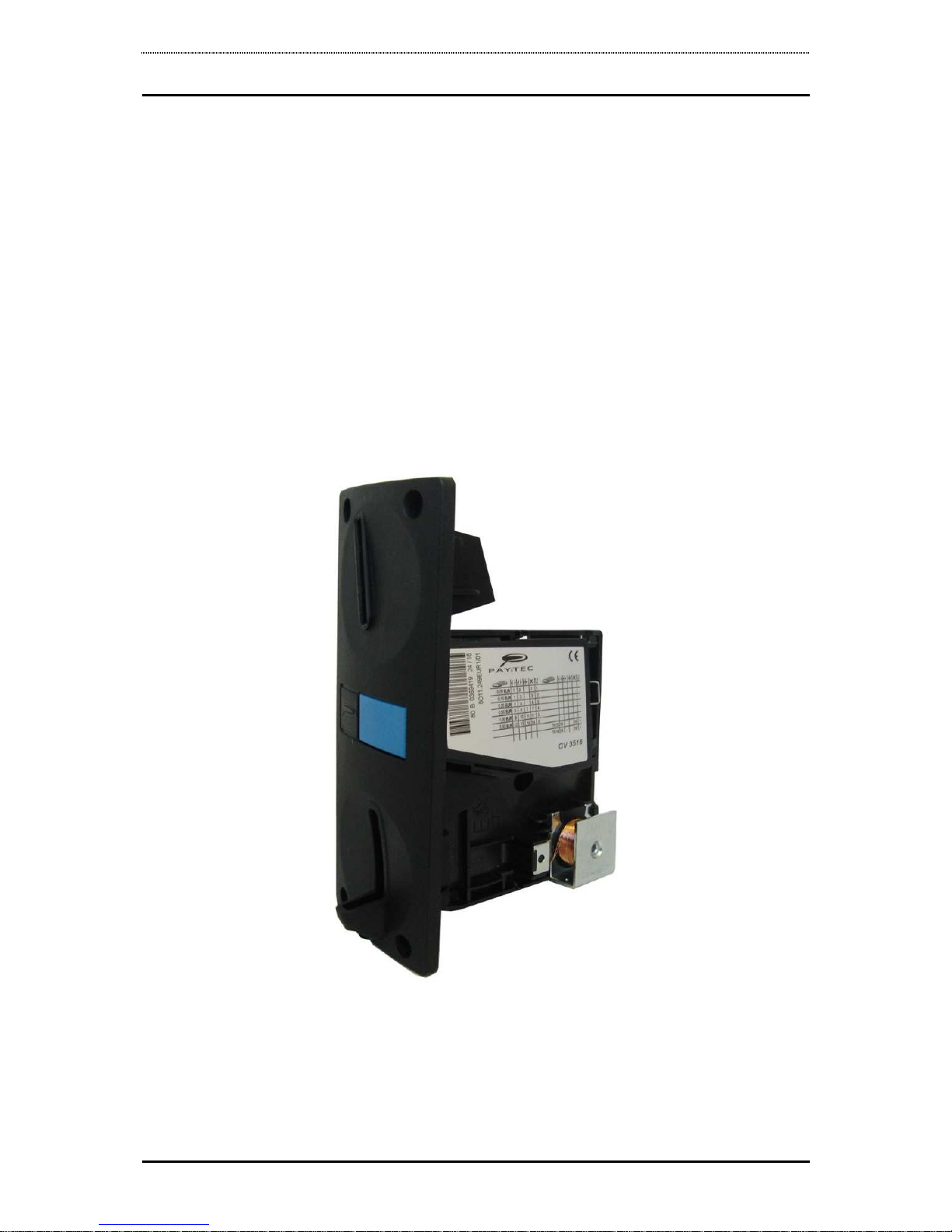
Coin validator
CV3516
Page 2

PAYTEC user guide CV3516
2/14
Table of Contents
1.
Preface to the Guide .............................................................................4
2.
Technical data ......................................................................................5
3.
Programming the coin validator (teach mode) ..........................................6
3.1. Parallel Output Connector ..............................................................7
3.2. Coin Blocking ................................................................................... 8
3.3. Coin blocking (general inhibit) ........................................................8
4.
Coin validator label ...............................................................................9
5.
Maintenance ...................................................................................... 10
5.1. Cleaning ........................................................................................ 10
5.2. Troubleshooting (malfunctioning) ..................................................... 11
6.
Connecting Diagrams .......................................................................... 12
7.
Dimensions ........................................................................................ 13
Page 3

PAYTEC user guide CV3516
page 3/14
The information contained in this manual is subject to change without prior notice and is
not binding for Payment Technologies S.r.l.
General warning
•
Read this guide carefully before use.
•
This guide is valid for the model CV3516
•
Before CV3516 is installed, check voltage compatibility with the Vending Machine
•
CV3516 has been designed for internal electrical equipment for Vending Machines
•
Do not use in water or near liquids where it might become wet
•
Do not use near smoke or inflammable gases
•
Cut power before maintaining electrical and/or mechanical components
•
Dispose of the device in accordance with environmental laws (DO NOT burn)
•
Always read labels
•
Do not tie the output cable
•
Periodically check whether cables are correctly plugged on their connectors
•
Do not use extension cables
•
Cut power before maintaining and/or cleaning the unit
•
Use a damp cloth to clean plastic elements
•
Keep the coin chute clean
Page 4
PAYTEC user guide CV3516
page 4/14
1. Preface to the Guide
This manual describes the functionality, adjustment and servicing of the
coin validator CV3516 (6 parallel output lines).
CV3516 is an electronic coin validator with a combined optical and
inductive measuring system. The measuring system consists of various
light barriers and coil alignments inserted in the main body.
CV3516 has 32 coin channels for a maximum of 16 different coins. If the
measured coin values of an inserted coin lie within all acceptance bands
of a programmed coin channel, then the coin validator assigns this coin
to this specified channel.
Normally at least 2 different acceptance bands are stored in a coin validator
for each coin to be accepted. Should the acceptance only be carried out in
the channel with narrow tolerance bands, the coin acceptance of the broad
channel must be blocked by switching mini-DIP switches (see coin label).
The measuring quality is primarily influenced by the steadiness
of the coin passing through the measuring system, with the
help of an integrated element which slows the coin down.
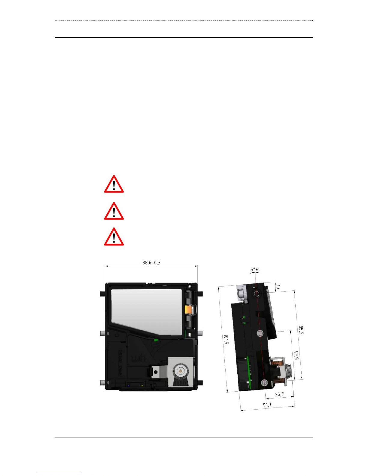
In general care should be taken to ensure an incline of 5° of
the coin validator, to make certain that the coins can pass
along the contact surface in an ideal way (see fig.1).
The coin insert should allow the coin to roll into the coin
validator by a minimum of kinetic energy.
Fig.1 CV3516 – Dimensions and positioning
Page 5
PAYTEC user guide CV3516
page 5/14
2. Technical data
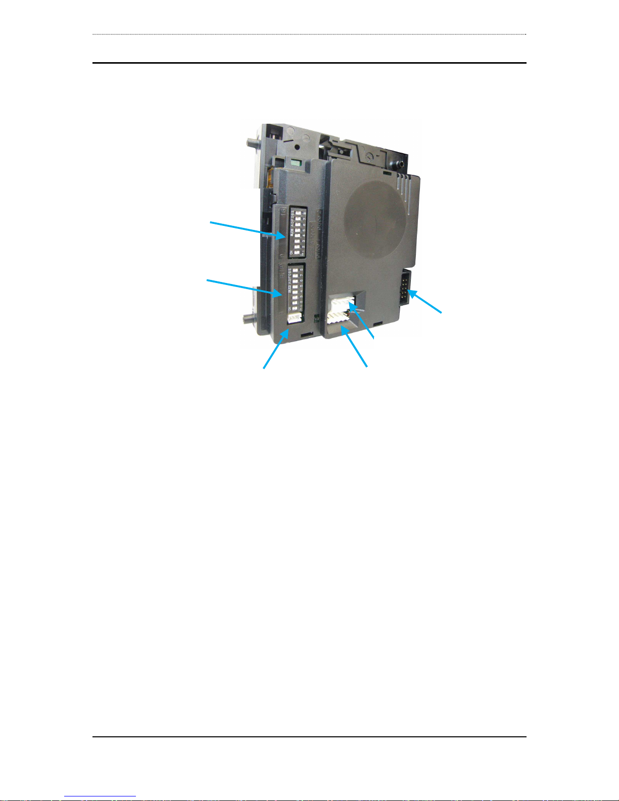
Fig. 2 Connectors and control elements
Coin acceptance 32 coin channels (by default)
2 channels free for each token
Coin blocking Complete blocking via signal transmitted by VMC or cashless
System. Any individual coin, or group of coins can also be
blocked through mini-DIP switches
Output signals Six open collector output lines (parallel) compliant with the
standard for vending (100 msecs approx.)
65 V / 100 mA (output lines 1 to 4)
45 V / 500 mA (output lines 5 and 6)
Supply voltage 10 V to 26 V DC
Supply current < 30 mA in standby; during coin acceptance briefly 450 mA
Start up 15 ms
Temperature range +10°C to +70 °C
Humidity classification annual average 65% R.H., maximum 60 days per year 85%
R.H., remaining days maximum 75% R.H., no condensation
Coin sizes max. diameter x max. thickness: 32.5 x 3.4 mm
Dimensions height x width x depth: 104 x 53 x 93.5 mm (without front
plate)
I
/O Parallel
unused
unused
mini-DIP
blocking switches
9 to 16
mini-DIP
blocking switches
1 to 8
unused
Page 6

PAYTEC user guide CV3516
page 6/14
3. Programming the coin validator (teach mode)
The coin selector can be delivered with an optional teach mode function.
Such function can be used to program two “token” channels (channels
no.15 and no.16), which are associated by default to coin output no.1.
The teach mode is activated by setting the number 8 switch on the left
side of the DIP switches to “ON” (fig.3). The number 7 switch of the same
DIP switch block is used to set the acceptance tolerance to “broad” or
“narrow”. The “ON” setting selects a narrow tolerance.
When observing the mini-DIP switches in fig.3, the left DIP switch on the
left side corresponds to channel 1 and right DIP switch on the right side
corresponds to channel 16 (16 coin channels).
Some mini-DIP switches have a special function:
• mini-DIP switch 7 is used to set the acceptance tolerance
• mini-DIP switch 8 is used to activate the "teach-mode"
• mini-DIP switches 1 to 14 are also used to block single coins, or to
activate/inhibit default tolerances for each coin channel (see coin
label)
• mini-DIP switches 15 and 16 are used to program two token
channels, each associated to output no.1
Fig. 3 below shows the example of setting up channel 15 for calibration
with narrow acceptance tolerances.
Fig. 3 Example DIP switch settings for teaching channel 15 with
narrow tolerances:
mini-DIP 8 ON “teach mode” activated
mini-DIP 7 ON teaching is effected using narrow tolerances
mini-DIP 15 ON channel 15 is used for teaching
To program the coin selector with the teach mode a minimum of 10
coins or tokens must be inserted. When the requisite number of coins
have been inserted and the teaching procedure has been completed (by
setting the blocking switch no.15 back to the OFF position), the coin
selector solenoid will operate briefly and once only.
Set the mini-DIP switches 7 and 8 back on "OFF".
Page 7

PAYTEC user guide CV3516
page 7/14
Warning!
The mini-DIP switches 15 e 16 have to be set to the OFF position when
activating the teach mode, otherwise the coin selector software blocks the
two channels for the teach mode.
If any coin blocking switches are activated (ON) for channels which are
not released for the teach mode, the coin selector magnet will operate
briefly three times to indicate an incorrect operation.
For security reasons during teaching, the token channel can be
programmed when the measured values of the tokens do not overlap the
values of the coins programmed, with mini-DIP switch 7 on OFF (broad
tolerance). Should the programming not be successful when using broad
tolerance, teaching could be still possible using the narrow tolerances
(mini-DIP switch 7 on ON).
The teach mode is deactivated by setting mini-DIP switch 8 on OFF. When
the teach mode is deactivated, all mini-DIP switches may then be used
for individual coin blocking with the exception of mini-DIP switch
3.1. Parallel Output Connector
The parallel output connector is a 10-pin, dual row jack. The connector
has the following pin out:
Pin No. Connection
1 GND
2 +Vcc
3 coin output 5
4 coin output 6
5 6 general blocking (input)
7 coin output 1
8 coin output 2
9 coin output 3
10 coin output 4
Fig. 4 10-pin male connector
Page 8

PAYTEC user guide CV3516
page 8/14
3.2. Coin Blocking
CV3516 is equipped with 16 mini-DIP switches to block coins. A coin is
normally accepted when the mini-DIP switch has been set on "OFF".
Coin channels correspond to more mini-DIP switches combinations. The
coin label indicates the corresponding mini-DIP blocking switch for each
channel (symbol X).
3.3. Coin blocking (general inhibit)
General blocking is activated with standard active “high” signal on pin 6
of the 10-pin connector (in this case che validator will not accept any
coin). Any voltage between 5 and 24 V DC is considered a high signal.
As a rule, coins are accepted with “GND” inh level (also known as “low”
level).
Following the tpe of connection (12V 10-pin connector, or 24V 16-pin
connector), VMCs or cashless systems give a different polarized signal.
Here are the standard signals:
12V 10-pin coin acceptance LOW (GND), coin blocking HIGH
24V 16-pin coin acceptance HIGH (+Vcc), coin blocking LOW (GND)
Since polarity does not change on the validator (coins accepted at LOW
level), the correct signal level has to be adjusted on the VMC, or on the
cashless system, connected.
On PAYTEC cashless systems the general inhibit level
can be adjusted with the palmtop P6000 in Function 00:
set "Input enable high = N"
On PAYTEC cashless systems the general inhibit level
can be also adjusted with the PC application "Paytec
Configurator". In that case, select coin validator
CV3516 24V.
Page 9

PAYTEC user guide CV3516
page 9/14
4. Coin validator label
The label of the coin validator has all the necessary information to
•
identify coins for each output line
•
configure mini-DIP switches so to block single coins
•
configure mini-DIP switches so to block acceptance bands for each
coin or group of coins
Fig. 5 Example of a CV3516 label
Label format and legend:
coin type (value and currency)
Teach mode channels are marked with TKn. “n” = number of
blocking switch, which has to be used to activate the teach
mode for this channel.
Blocking switch for the broad channel
Blocking switch for the narrow channel
Blocking switch for the very narrow channel
Blocking switch for a coin type or coin group
Output line (output signal no.)
The output line for CV3516 is a number between 1 and 6.
Page 10

PAYTEC user guide CV3516
page 10/14
5. Maintenance
5.1. Cleaning
CV3516 operates relatively maintenance free. However, it should be
cleaned at regular intervals especially if it is operating in an environment
with high levels of dust, smoke or nicotine. The cleaning intervals are of
course dependent on the level of air borne contaminants.
Modest use with minimum contaminant levels indicate the need to clean
the top of the coin path once a year. Open the coin path door and wipe
the exposed surfaces with a cloth moistened with lukewarm water and a
little washing-up liquid. The light sensors may be cleaned with a soft brush
or air duster spray.
Make sure that the coin validator is without power during the
cleaning
Use a damp - not wet - cloth. Under no circumstances liquid
should run into the coin validator
Avoid solvent or abrasives which may ruin the plastic material
Never use an oily rag! Never lubricate the solenoid, hinge
joints, etc.
The consumption of current is raised for short period of time (40 ms)
when the solenoid is activated. Make sure that the voltage does not drop
below 8 volts when a load of 400 mA is applied.
Page 11

PAYTEC user guide CV3516
page 11/14
5.2. Troubleshooting (malfunctioning)
Not every malfunction is caused by a defect of the coin validator. Often it
is caused by spoiled or loose connecting cables, wrong adjustments or a
weak current supply.
The following chart gives you a survey of the most common malfunctions.
Problem Possible reason Solution
The
validator
does not
accept any
coins
no power supply • Apply power to the device and
ensure that the power supply
really provides voltage
• Check condition of cable
Power supply too
weak
The consumption of current is
raised for short period of time
(40 ms) when the solenoid is
activated. Make sure that the
voltage does not drop below 8
volts when a load of 400 mA
is applied.
Coin blocked • Check whether the coins are
blocked via mini DIP-switches
• Make sure that the coin
selector is not blocked by the
controller via the signal
“General Blocking” (pin 6)
Soiled Coin Selector • Clean Coin Selector
Reject button • Make sure the reject button is
not actuated (blue button)
Soiled light barrier at
coin exit or blocked
by an object
• Clean light barrier
• Remove foreign object from
the coin exit
Coin
validator
accepts
coins, but
does not
give an
output
signal
Coin exit is blocked
so that the coin
stays too long in the
light barrier or
bounces again after
leaving the light
barrier
• Make sure, that the coin exit
is not blocked by any foreign
objects
Page 12

PAYTEC user guide CV3516
page 12/14
6. Connecting Diagrams
t used
Fig. 6 – Connecting diagram CV3516
3
2
6
4
9
8
7
5
1
10
VI
GND
VO
GND
GND
GND
GND
GND
VC C
EMP 8x0.00
Ground
5
4
3
2
1
Output line 1
Blocking
Reject
Output line 5
Output line 6 or i nventory
St-EMP
Connector ST1 for SCI or MDB mode and programming
Output line 4
Output line 3
Output line 2
+10 .. +26V
( )
Vending Machine
GND
GND
GND
GND
GND
GND
GND
GND
2
6
4
3
8
7
1
10
9
5
CV
3516
VMC / CASHLESS
not used
Page 13

PAYTEC user guide CV3516
page 13/14
7. Dimensions
Page 14

PAYTEC user guide CV3516
page 14/14
PAYMENT TECHNOLOGIES S.r.l.
ITALIA
via XX Settembre 49 - 22069 ROVELLASCA (CO)
TEL (++39) 02 9696141 - FAX (++39) 02 96961414
www.paytec.it info@paytec.it
DISTRIBUTOR
 Loading...