

Paxton
ins-40213-US
Paxlock US
3
2*
1
16
15
5
9
4
8
6
7
17
18
19*
10
11
20
12
14
13
21
22
x 2 x 2
X 3
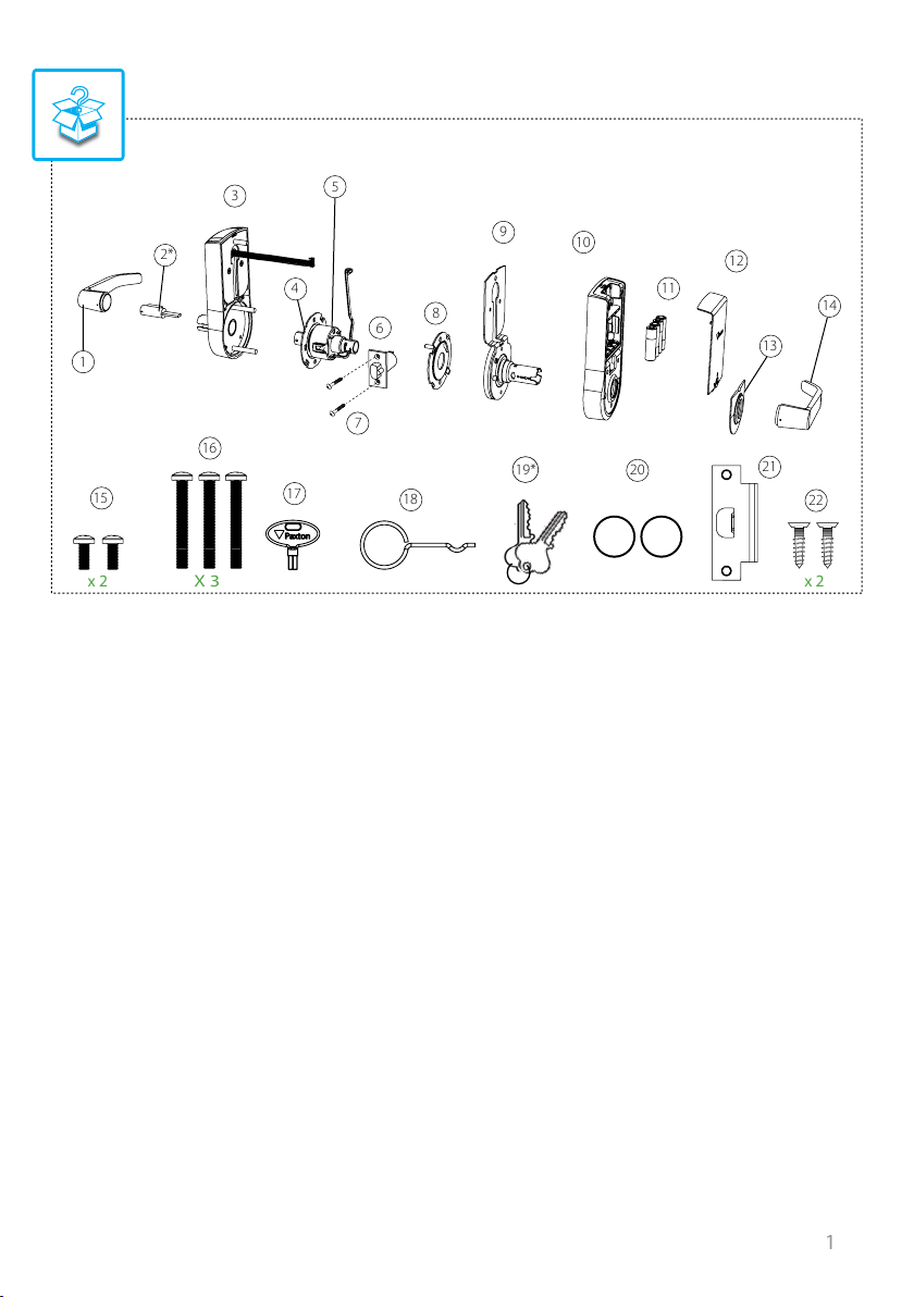
What’s in the box
1) Front handle
2) Lock Cylinder *
3) Paxlock front housing
4) Motor adjustment plate
5) Motor
6) 2-3/8” Latch
7) Latch screws x 2
8) Motor backplate
9) Backplate/Rose assembly
10) Paxlock rear housing
11) 4 x AA Alkaline batteries
* Not for SFIC
12) Rear battery cover
13) Rear handle cover
14) Rear Handle
15) Small mounting screws x 2
16) Long mounting screws x 3
17) Battery cover key
18) Handle removal pin
19) Keys x 2 *
20) Handle washers x 2
21) Strike plate
22) Strike plate screws x 2
Tools List
Power Drill
Drill bits (1”, 5/16”, 5/8”, 1/8”)
Crosshead screwdriver
Chisel 1”
Knife
Adhesive tape
Pencil
Tape measure
1
1
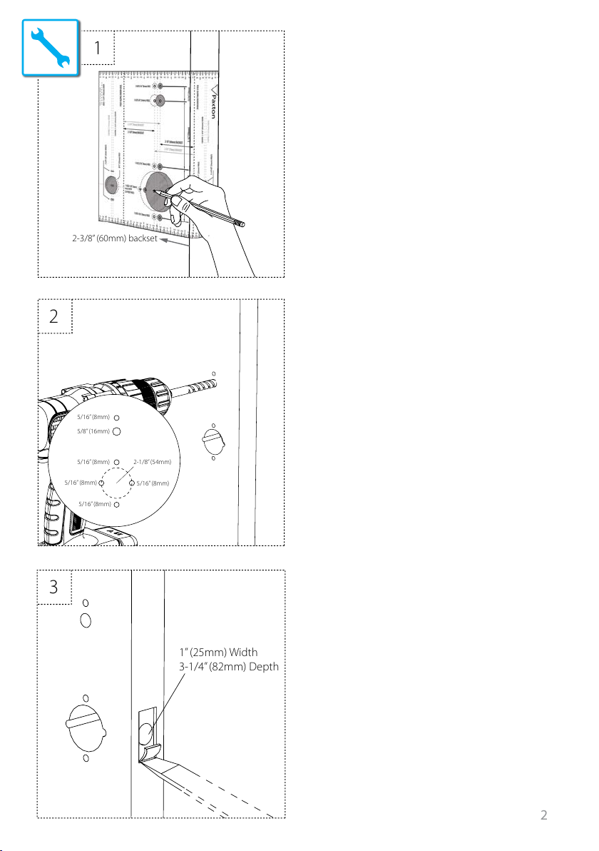
2-3/8” (60mm) backset
Step 1: Marking out
Tape template to door, mark holes then remove
template for drilling.
2
3
5/16” (8mm)
5/8” (16mm)
5/16” (8mm)
5/16” (8mm)
5/16” (8mm)
2-1/8” (54mm)
5/16” (8mm)
1” (25mm) Width
3-1/4” (82mm) Depth
Step 2: Drilling
To ensure accuracy you should drill holes from
both sides of the door towards the center. This
avoids the risk of damaging the door face when
the drill breaks through.
Make sure to include pilot holes either side of
the central hole to ensure ush tting of the
motor plates.
Step 3: Marking out and chiseling for latch
To install the latch; drill a 1” (25mm) hole, slide in
the latch, then draw around the faceplate.
Remove the latch and score the outline with
a knife to avoid splitting the wood when
chiselling.
2
4
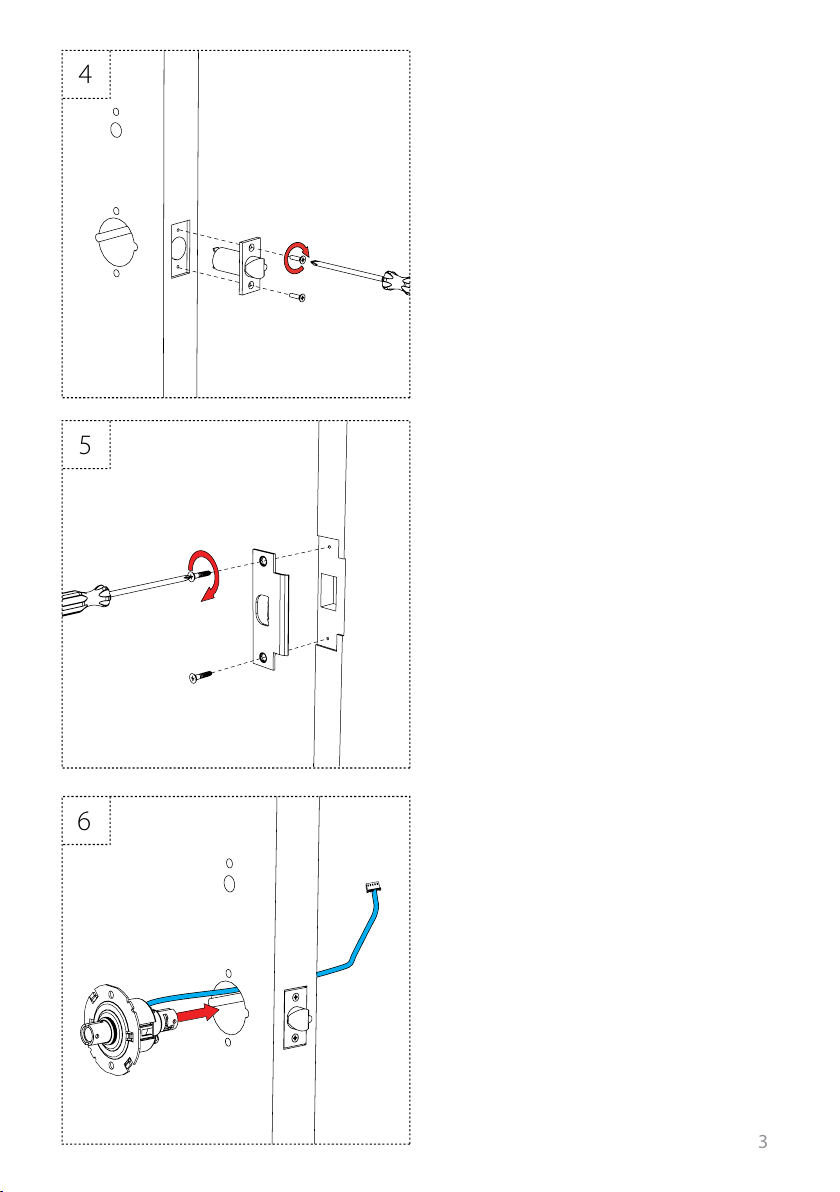
Step 4: Fitting the door latch
Attach the latch using the screws provided.
5
Step 5: Fitting the strike plate
Close the door to mark the horizontal line of the
strike plate.
Measure one half of door thickness from door
stop to mark vertical center line of the strike.
Drill 1” (25.4mm) hole, 1/2” (12.7mm) deep at
intersection of horizontal and vertical center
lines.
Cut out jamb 3/32” (2.4mm) deep or until the
strike is ush with jamb. Tighten the strike plate
screws securely.
Step 6: Inserting the motor
6
Pass the motor through the central hole within
the door, making sure to pass the motor lead
through the hole rst.
3
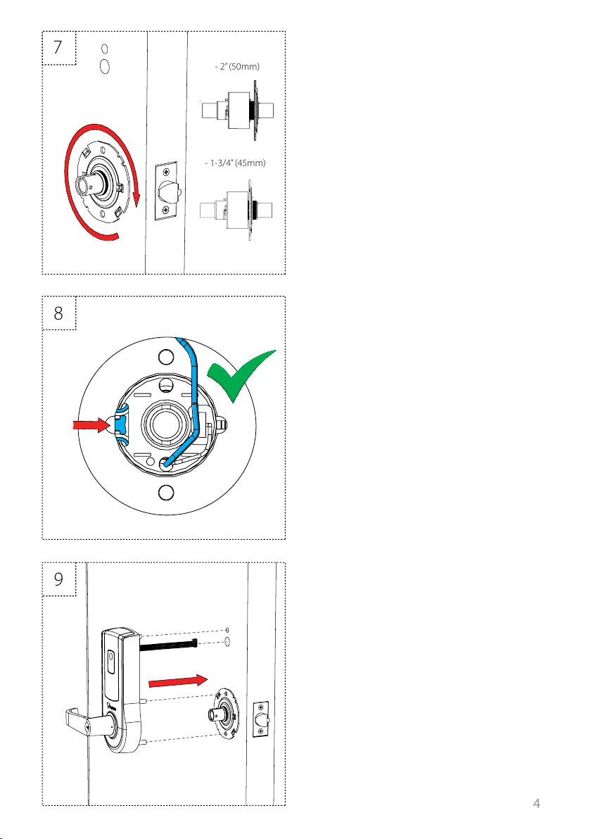
7
Step 7: Rotating the motor adjustment plate
- 2” (50mm)
- 1-3/4” (45mm)
To ensure that the motor adjustment plate is at
the correct distance, rotate until it sits ush with
the door and the motor has engaged properly.
Please refer to the diagram for the correct
position of the plate for each door thickness.
8
Step 8: Ensuring the latch engages
Make sure the tail of the latch is engaging with
the motor retractor correctly as illustrated.
Step 9: Fitting the front housing
9
Line up front housing and ensure the body is
ush to the door.
*PaxLock US is set up for RH doors by default –
please see page 8 for LH operation.
4

13
14
15
10
Step 10: Fitting the rear backplate
assembly
Feed the motor cable through the
hole in the motor back plate.
11
12
Step 11: Fitting the rear housing and motor
wiring
Feed both the cables through the rear housing
cutout and t the lower long mounting screws.
Step 12: Fitting the rear lock assembly and
wiring
Fit top, long mounting screws and 2 lower short
screws.
5

13
Step 10: Fitting the batteries
14
15
Step 11: Securing the rear cover
Step 12: Fitting the cover plate and handle
6

Optional step: Handle orientation for LH door
To congure for LH door operation, remove the front and rear handles using the handle removal
pin. Unscrew the 4 screws securing the rose to the front/rear housings, rotate 180 degrees and
screw back together.
Ret the handles, and push home until the axle engagement clicks.
Optional step: Contact switch Optional step: Inserting the handle washers
Handle feel can be tightened with the use of
the included washers.
7

Software installation
0 m
3m
15m
20m
30m
50ft
65ft
100ft
10ft
0 ft
≤ 200
Net2 Pro/Net2 Lite: http://paxton.info/1438
Wireless Signal Range
x1
x1
≤ 1000
8

1
2
4
5
6
3
Enrolling a PaxLock
1
4
2
3
21
43
9

PaxLock reset
1
3
Battery replacement
2
4
21
43
10

Specications
Features
Maximum number of users/tokens
Access Levels
Time zones
Door unlock time
Recommended number of Paxlock’s per Net2Air bridge
Net2Air bridge per system
Net2Air wireless range
Events stored
Environment
Battery type
Typical Battery life
Operating temperature
Moisture resistance
External Use
Vandal resistance
Dimensions
Total outside dimensions (includes handle clearance)
UL has only evaluated the Operating temperature specication
Min
1 sec 60 secs
50 ft
Min
4 x AA Alkaline
20,000 operations 30,000 operations
0 °C (-32 °F)
IPX4
No
No
Width Height
6” 8
1/2
” 3”
MaxTyp
10,000
250
64
10
200
3,584
Max
+55 °C (+131°F)
Depth
11

+44 (0)1273 811011
support@paxton.co.uk
paxton.support
+44 (0)1273 811011
support@paxton.co.uk
paxton.support
+1(800) 672-7298
supportUS@paxton-access.com
usapaxton.support
+1(800) 672-7298
supportUS@paxton-access.com
usapaxton.support
+49 (0) 251 2080 6900
support@paxton-gmbh.de
paxton.gmbh.support
+31 (0)76 3333 999
support@paxton-benelux.com
paxton.benelux.support
+31 (0)76 3333 999
support@paxton-benelux.com
paxton.benelux.support
+31 (0)76 3333 999
support@paxton-benelux.com
paxton.benelux.support
+33 (0)157 329356
support@paxtonaccess.fr
paxton.support
+27 (0) 272 14276691
support@paxtonaccess.co.za
paxton.support
+44 (0)1273 811011
support@paxton.co.uk
paxton.support
12

The declaration of conformity is available on request. Contact details are provided at:
http://paxton.info/596
These products are not suitable for retail sale. All warranties are invalid if these products are not installed
by a competent person.
North America:-
Product Compliance and limitations
Wiring methods shall be in accordance with the National Electrical Code (ANSI/NFPA70), local codes, and the authorities
having jurisdiction.
To comply as a UL listed installation, the following conditions must apply:-
• Server based functions (Antipassback, Time and Attendance, etc) have not been evaluated by UL and cannot be
used for UL 294 installations.
• Where an equivalent cable / wire is used it must be ‘ UL Listed ‘All interconnecting devices must be UL Listed.
• The use of Wiegand readers and the conguration software has not been evaluated by ‘UL’
• Door contact connections are limited to a maximum of 30m.
• IP rating not veried by UL.
• Indoor use only
UL listed to the following standards: ANSI/UL 10C compliant (20 min re doors), CAN/ULC S104 compliant (20 min re
doors), UL 294 compliant, CSA C22.2 NO. 205-12 compliant
FCC Compliance
This device complies with Part 15 of the FCC Rules. Operation is subject to the following two conditions:
(1) this device may not cause harmful interference, and (2) this device must accept any interference received, including
interference that may cause undesired operation.
Changes or modications not expressly approved by the party responsible for compliance could void the user's authority
to operate the equipment.
The Paxlock US has been designed and complies with the safety requirements for portable (<20cm) RF exposure in accordance with FCC rule part 2.1093 and KDB 447498 D01 as demonstrated in the RF exposure analysis. Installers must
ensure that this device must not be co-located or operated in conjunction with any other antenna or transmitter except
in accordance with FCC multi-transmitter product procedures.
IC Compliance
This device complies with Industry Canada licence-exempt RSS standard(s).
Operation is subject to the following two conditions:
(1) this device may not cause interference, and (2) this device must accept any interference, including interference that
may cause undesired operation of the device.
The Paxlock US has been designed and complies with the safety requirements for RF exposure in accordance with RSS102 as demonstrated in the RF exposure analysis.
13

14

Made in the UK
© Paxton Ltd 22/10/2014
1.0.0
 Loading...