

Page 1
Page
1
Ins-30051 : OEM Hands free interface, Clock & Data output
25/03/2010
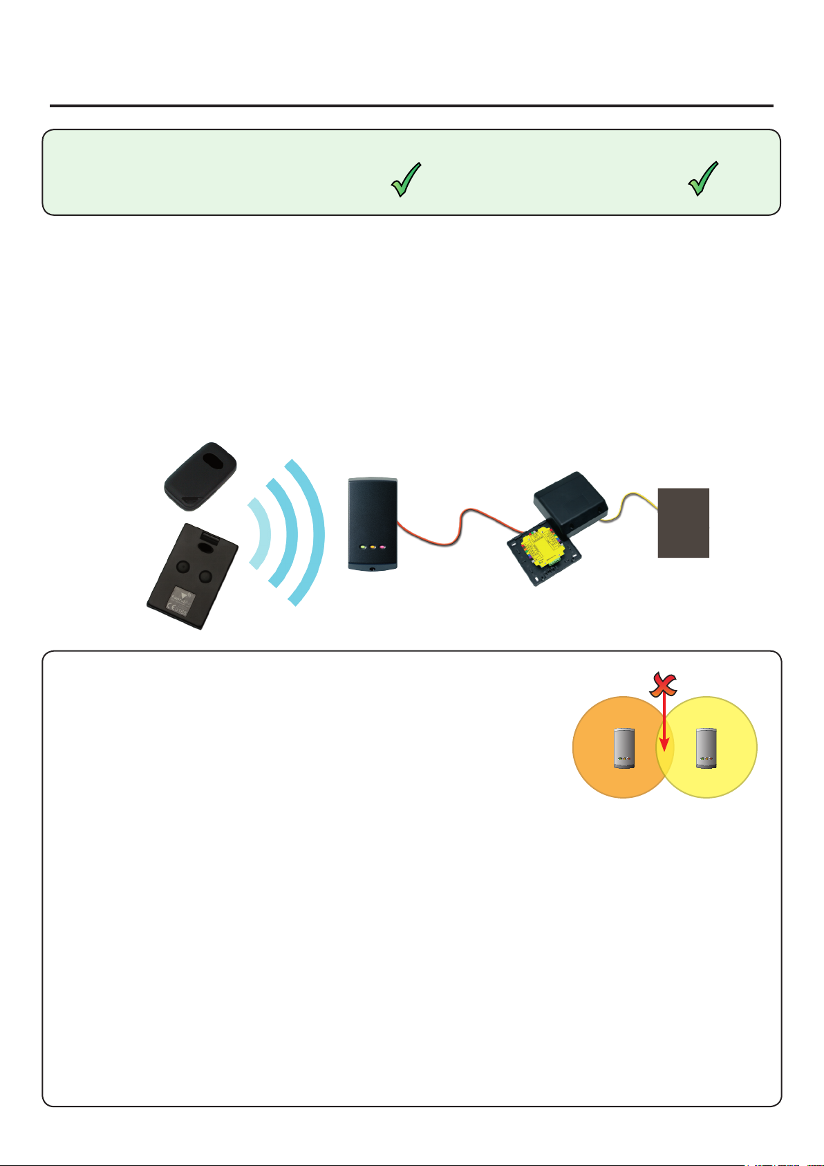
The system comprises of a hands free interface, a compatible reader (see specication table) and hands free
tokens (keycard or keyfob). The system operates by using the eld being transmitted by the reader to wake up
the token which then communicates with the interface which contains a long range receiver.
Existing P series readers can be used without modication. The hands free interface takes its power from the
control unit and therefore does not require a power supply.
Hands free tokens also include a standard EM4100 proximity ID chip and can therefore be presented to any
compatible proximity reader whether they are using the hands free interface or not.
What is hands free?
Before you install
Read in, read out
When using in and out readers, users may be picked up by both readers as they move through the door which
will reduce the reliability of any roll call or anti-passback application. Ensure that sufcient spacing is provided
between these readers for optimum range and reliability.
Positioning readers
For maximum read range the hands free reader eld should not be overlapped by the eld from other
interference sources at or around 125 kHz. These include Loop readers, OEM readers, etc.
Readers should not be positioned so that their active elds overlap.
(see table on back page for typical hands free read ranges)
For example, the minimum distance between a P200 and a P50 reader should
be 3.6 m (P200 hands free range = 2.5 m + P50 hands free range = 1.1 m)
Hands free keyfob
Hands free keycard
P series reader
Hands free interface
OEM control unit
For optimum keyfob battery life please choose your reader location carefully to avoid placing it within hands
free range of work stations, rest or smoking areas.
Positioning the interface
The interface should be positioned as close as practical to the reader. A distance from interface to reader of
10 to 15 meters can be achieved but wireless technology is susceptible to environmental factors and so if
problems are experienced it may be necessary to move the interface closer to the reader.
The hands free interface should not be housed in a metal enclosure as it contains the main receiver aerial.
Sticky feet allow the interface to be stuck to the ACU wiring label in a PSU plastic housing.
Suitability
Compatible with hands free readers
Security-sensitive doors
Page 2

Page
2
Wiring
12V
Red LED
Amber LED
Green LED
Data/D0
Clock/D1
Media detect
Entry
0V
Reader
Entry conrm
12V
Red LED
Amber LED
Green LED
Data/D0
Clock/D1
Media detect
Entry
0V
Net2 Control Unit
0V
Exit/Entry
Green LED
12V
Net2Air Interface
Entry conrmation button
(optional)
Input terminal
(FOR FUTURE USE)
Readers can be extended using Belden CR9540 10-core overall screened cable to a maximum of 100 metres.
Cable extensions
Using an entry conrmation button
Where two door readers may pick up the same hands free token, a push to make button can be used to conrm
an entry request for the specic door. Where tted, the button LED will ash for 5 seconds after the hands free
token has been recognised and must be pressed to unlock the door.
Conguration
Firmware download
Hands free rmware for the P series reader will be downloaded from the interface to the reader as soon as it is
powered up. This is indicated by ashing amber and red LED’s on the reader. Once complete all LED’s will be lit.
This may take up to 10 minutes to complete. Do NOT disconnect power during the rmware update.
If the rmware update is still taking place after 10 minutes then remove and then re-connect the ACU cable.
Listen to the reader, the reader should NOT beep. If the reader beeps within approximately 10 seconds of power
up it will not take the rmware update. Repeat the process until the reader does NOT ‘beep’ on power up. Then
leave for 10 mins to allow the update to take place.
To enable the use of an entry conrmation button do the following steps:
1. Power down the interface board
2. Power up the interface board
3. Press and hold the entry conrmation button for a minumum of 3 seconds within 60 seconds of power up.
To disable the use of the button, repeat the above process.
*
+12V DC
Red LED
Amber LED
Green LED
Data
Clock
Not Required
0V
*
Page 3

Page
3
Changing frequency channel
If you are experiencing problems with the range or reliability this may be due to poor reader positioning, adjacent
interfering 125 kHz or 2.4 GHz equipment, e.g. an adjacent wireless PC network. Please refer to the ‘Before you
install’ information regarding unit locations. If you are still unable to improve the system performance then you
may try an alternative 2.4 GHz channel using Switch 1. Power cycle the unit after any changes.
The system has 16 channels available. (Unless a keycard xed channel is selected) The unit is set to channel 4
as this frequency is normally clear of other device transmissions. This can be changed using a small at blade
screwdriver. Take care not to contact the circuit board with the screwdriver blade as this may damage components.
SW2 - Keycard button 1 and 2 xed channels - If either switch 1 (Channel 26) or switch 2 (Channel 11) is set, the
rotary frequency switch is disabled. If both switches are selected, the interface will not operate.
0 2.405 11
1 2.41 12
2 2.415 13
3 2.42 14
4 2.425 15
5 2.43 16
6 2.435 17
7 2.44 18
8 2.445 19
9 2.45 20
A 2.455 21
B 2.46 22
C 2.465 23
D 2.47 24
E 2.475 25
F 2.48 26
SW1. Rotate the switch to select an
alternate channel.
The hands free tokens wil automatically congure themselves to use the new channel.
GHz
Switch
position
The switch will initially be set to default position ‘4’
IEEE 802.15.4
channel
Switch SW2 is used to select the xed channels used by the two keycard buttons. Select either switch 1 or 2
to set which keycard button the interface will respond to.
The unit must be power cycled if the switch position is changed, to activate the new setting.
Interface PCB
To enable the buttons, the keycard must rst be presented to the P series reader and then used in hands free
mode. The keycard stores the details of this interface and can then activate the door using a button.
It can also be used in normal hands free mode and also in local passive mode with other standard readers.
Conguring the interface to work with keycards
Page 4

Page
4
71 mm
70 mm
23 mm
11V DC 14V DC
80 mA
2.4 GHz
600 µs
No
1
Yes
Beldon 9540
100 m
15 m
P38 850 mm
P50 1100 mm
P75 1500 mm
P200 2500 mm
2000 mm
-20 °C 55 °C
Specications
Voltage
Clock and data bit period
Carrier frequency
Operating temperatures - all items
Electrical
Environment
Dimensions
Min
Max
Width
Height
Depth
Current
P200E metal mount
Readers per interface
Cable type for extensions
Cable length between ACU and reader
Distance between interface and reader
Read range with hands free token
System Specication
Waterproof
Additional power supply required
NO - If used externally, it must be protected in a plastic weatherproof housing
Button conrmation input
 Loading...