

Page 1

e l b a e g r a h c e R d e l a e S
B a tte r y
h A 7 V 2 1
V 2 1
V 0
V 2 1
V 0
V 2 1
V 0
U S P
V 0
0V
0V
0V
0V
0V
+12V
0V
0V
0V
0V
0V
r e w o P s t u p n I
2 r e d a e R 1 r e d a e R
Red
Brown
Orange
Green
Yellow
Blue
Mauve
Black
Red
Brown
Orange
Green
Yellow
Blue
Mauve
Black
Relay 1 Relay 2 Relay 3 Relay 4
INPUT AC 100-240V
Model No: 411-xxx
Read installation instructions
before connecting the supply
50 / 60 Hz
1.2A
INPUT AC 100-240V
Model No: 411-***
Read installation instructions
before connecting the supply
50/60Hz, 1.2A
OUTPUT DC 13.8V, 2A
PSU Ratings:
28/06/2012
Ins-30043 I/O board with 2A/12V DC boxed power supply
Technical Support
01273 811011 support@paxton.co.uk
Technical help is available: Monday - Friday from 07:00 - 19:00 (GMT)
Saturday from 09:00 - 13:00 (GMT)
Documentation on all Paxton products can be found on our website - http://www.paxton.co.uk/
Layout
12V DC Outputs
Paxton I/O control board
Paxton
Tamper Switch
Mains Monitoring
Ratings Label
Back-up battery
PSU
MAINS POWER
Page 2
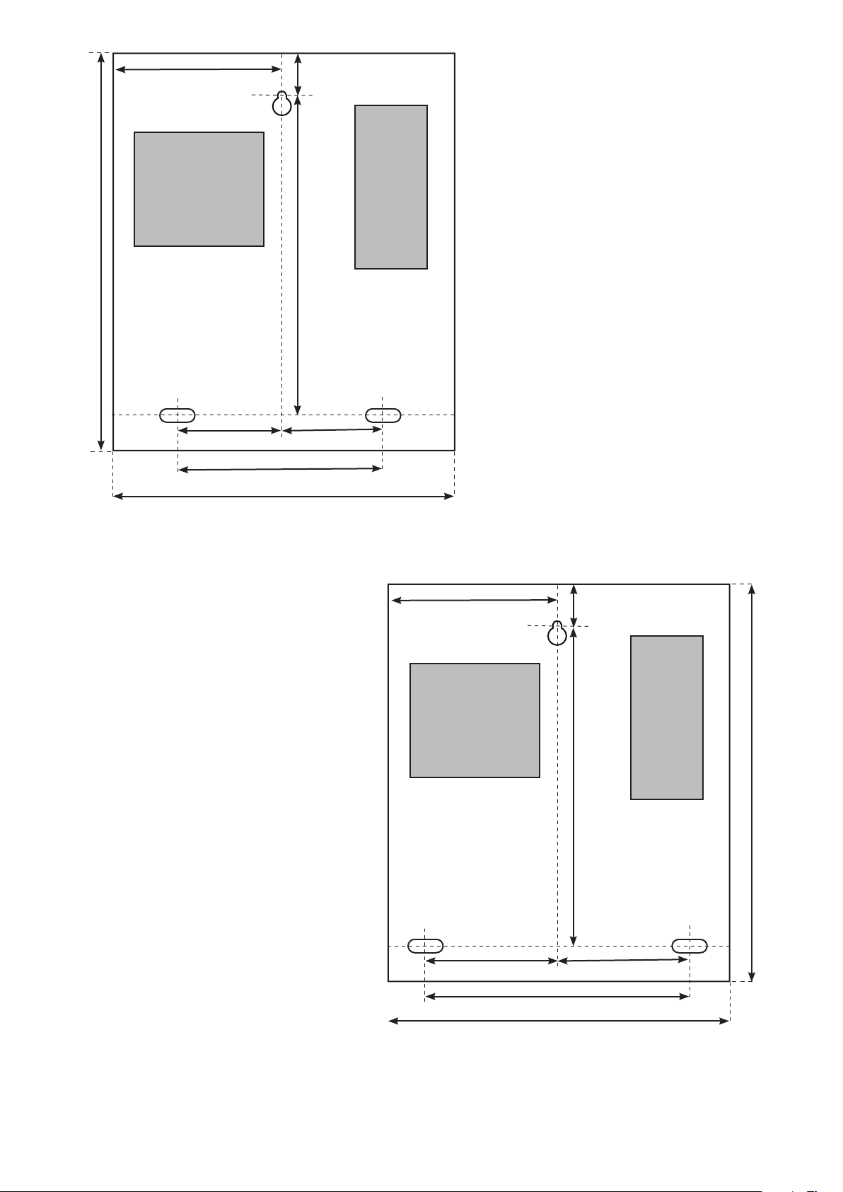
116 mm
25 mm
Fitting
1. Screws and wall plugs are provided in a tting
kit. With reference to the diagrams, determine
where the top, central mounting position is required
and drill a hole suitable for a No 8 wall plug.
2. Tap in one of the wall plugs.
320 mm
Metal Cabinet
68 mm
AC Mains Connection
Cabling
136 mm
232 mm
268 mm
68 mm
3. Put in one of the long screws, leaving a suitable
gap to the wall surface and slide the cabinet over it.
4. Mark the hole positions for the lower 2 screws.
5. Remove the cabinet and drill the additional holes.
6. Tap in the 2 wall plugs and hang the cabinet back
onto the top screw.
7. Secure the cabinet with the 2 lower screws.
8. Tighten the top screw.
118 mm
18 mm
A detachable gure 8 power cable is
provided with the unit. This is prestripped at one end for connection to a
fused spur.
Anchor points are supplied inside the
case to secure the incoming mains cable.
(cable tidy/ties are provided) There are
also 'knock-outs' in the case to allow
convenient access for the cable.
Ensure that the supplied compression
gland is used when passing the mains
cable through any holes in the cabinet.
The power supply is double insulated and
requires no additional earth connection.
The PSU's battery function will not work
until this unit has rst been connected
to the mains supply. It is the loss of this
supply that switches the unit to battery
power.
Plastic Cabinet
320 mm
284 mm
98 mm98 mm
196 mm
236 mm
This product is not suitable for retail sale. All warranties are invalid
if this product is not installed by a competent person.
Page 3

Status Lights
Green
Red
This LED is on when the input supply is healthy.
This LED is on when the input supply has failed - Power is being supplied by the battery.
Features
Battery backup
Fast/Trickle charge
Deep discharge protection
Mains failure alarm (PSU)
Tamper alarm
The cabinet can accommodate a 12V / 7Ah battery.
The battery is continuously charged to keep it at maximum capacity.
If battery voltage falls below 9.5V, it will automatically disconnect - Red LED goes out.
Registers an alarm if the mains power fails when connected to an ACU or I/O board.
Registers an alarm if the lid is opened when connected to an ACU or I/O board.
Statement of Conformity
The Low Voltage (LVD) Directive - 2006/95/EC
The Electro-Magnetic Compatibility (EMC) Directive - 2004/108/EC
The Restriction of Hazardous Substances (RoHS) Directive - 2002/95/EC
Specications
Environment
Operating temperatures - all items
PSU Electrical
Output voltage
Maximum load output current
Maximum battery charging current
Mains supply voltage
Mains supply current
Mains supply frequency
I/O Electrical Min
Relay inputs
Relay output
Relay voltage rating
Relay current rating
Relay contact isolation
Current
*This max value is for when all four relays are energised
Dimensions
Metal Cabinet
Plastic Cabinet
Battery Compartment (Plastic Housing)
Min
-20 °C +45 °C
Min
13V DC 13.8V DC
100V AC 240V AC +/- 10%
50 Hz 60 Hz +/- 3 Hz
Width
232 mm 320 mm
236 mm 320 mm
150 mm 100 mm
Max
Max
2A
1A
1.2A
Max
4
4
240V AC
13 A
4 kV AC
* 400 mA
Height
Depth
80 mm
80 mm
62 mm
WARNINGS
:The following warnings and instructions MUST be adhered to. Read the instructions before installing and powering
the equipment. Keep the instructions in a safe place for future reference.
:RECEIVING INSPECTION- Remove any traces of packing material from the unit as such debris may create a re or shock
hazard. Unpack the unit with care and inspect for transit damage. If damage is suspected, the unit must not be used or tested,
but should be returned to Paxton for investigation and the damage reported to the carrier.
:INSTALLATION- Only qualied and trained personnel, familiar with this type of product and who fully understand these
instructions should install, connect or test this equipment. There are no user serviceable parts within the PSU unit.
:- The equipment is intended for indoor use only in dry locations. This is a Class A product. In a domestic environment this
product may cause radio interference in which case the user may be required to take adequate measures.
:- The installation must meet National Wiring Regulations and IEC60950-1 standards.
:- Disconnect Devices: A readily accessible disconnect device shall be incorporated in the building wiring to include an
appropriately rated circuit breaker to disconnect both poles with at least a 3.0 mm contact gap. After switch off, all internal
capacitors will discharge to safe levels within 60 seconds under normal conditions. Under fault conditions, charge may be held for
much longer and suitable precautions should be taken before handling the unit.
:- Protection device: The fusing characteristics of the protection device to be used are T3.15AH250V
 Loading...