

Page 1
04/02/2010
Ins-30142 Hands free demonstration unit
Technical Support
01273 811011 support@paxton.co.uk
Technical help is available: Monday - Friday from 07:00 - 19:00 (GMT)
Saturday from 09:00 - 13:00 (GMT)
Documentation on all Paxton products can be found on our website - http://www.paxton.co.uk/
Paxton
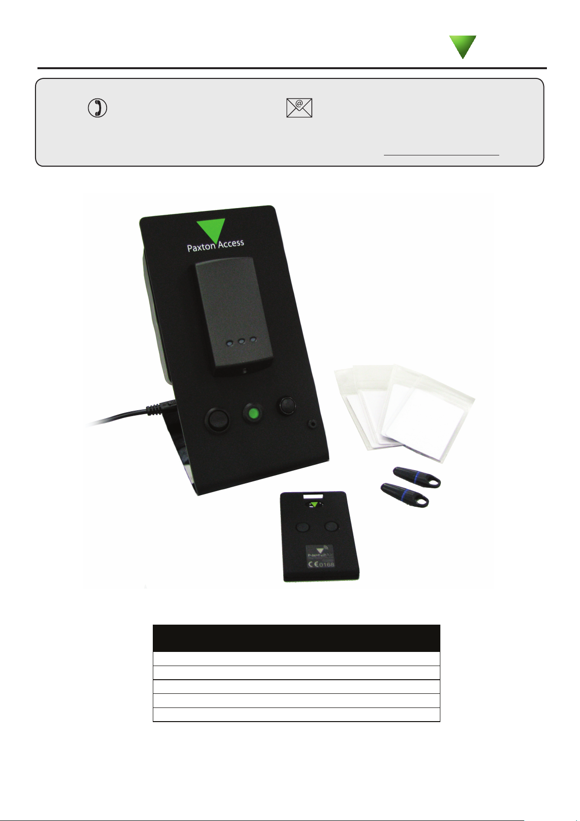
What’s in the box?
Hands free demonstration unit
Figure 8 IEC power lead.
Net2 demonstration cards and keyfobs
Hands free keycard
Documentation
Page 1
Page 2

Operation
QThe system comprises of a standard P50 proximity reader and a hands free interface.
1. Power up.
QPower up the unit and the reader LED’s will cycle through while the unit congures itself.
QAll 3 LED’s will now be lit.
QThis unit has been loaded with modied software to demonstrate the wireless range and exibility of
Q the Net2Air Hands free system. The reader will respond to a token with a beep and a ashing Green
Q LED as soon as a valid read is achieved.
2. Presenting passive tokens.
QA range of standard Net2 tokens is included for comparison tests. Present any Paxton or EM4100 token
Q to the reader. The reader will beep at the normal passive read range.
3. The keycard.
QA hands free keycard is provided. This card can be used in three ways:
Q i. Passive - The keycard contains an ID chip that any P series unit can read up to 80 mm.
Qii. Active - The keycard has a hands free transmitter/receiver that will operate up to 1100 mm.
Q Bring the keycard into range and the unit will respond using the hands free interface.
Q The keycard must be then taken out of range again before a second read can take place.
Qiii. Manual - The keycard transmitter can be activated from button 1. (Left). Pressing this button will
Q produce a response up to 50 metres from the reader. Button 2 in not active on this card.
Q The push button on the stand is not active with this demonstration system.
Page 2
Page 3

.
.
Green
White/Green
1
Screen or spare cores from
network cable
White/Orange
3
Orange
4
KR 1 redae dapye
1
Rleay2 Rleay1
Keypad2 Reader 2
stupnI P ewo r
CA nidoc elbac 5T g
krowteN
Net2 classic
2
Red 12V dc
Red LED
Amber LED
Green LED
Data/D0
Clock/D1
Media Detect
0V out
Load
Data
Clock
R cd V21 de
R DEL de
DEL rebmA
DEL neerG
0D/ataD
1D/kcolC
tc
e
t
e
D
aid
e
M
tuo V0
daoL
ataD
kcolC
PSU
F :noituaC ro ylno sredaer c.d V21 . F tcerroc ro
noitcennoc fo fer sre
d
aer V5 dlo re ot
sn
oitcurtsni
PLACE SERIAL
NUMBER
LABEL HERE
http://paxton.info/107
123456
AN1082 - Hands free - How does it work?
The hands free system increases the effective read range of a standard Paxton P or KP series
reader to a maximum of 2.5 metres.
The system comprises of a hands free interface, a compatible reader (see read range table) and
hands free tokens (keycard or keyfob). The system operates by using the eld being transmitted
by the P series reader. This wakes up the token which then communicates with the interface. The
interface contains a long range receiver aerial.
Existing P and KP readers can be used without modication. The hands free interface takes its
Hands free keyfob
Net2 control unit
P series reader
Switch2 control unit
Hands free interface
Hands free keycard
power from the control unit and therefore does not require a power supply.
Hands free tokens also include a standard PROXIMITY ID chip and can therefore be presented to
any compatible proximity reader whether they are using the hands free interface or not.
Overview
The P series reader is constantly transmitting the address of the interface it is connected to.
When the hands free token comes in range, it wakes up and transmits its card number to the
interface just identied. This ensures that it
only communicates with the correct interface
board, allowing several interface boards to
be placed within range of each other.
The token then shuts down for two seconds
to stop repeated transmissions and preserve
battery life. After this two second period,
the token checks to see if it is still in the
same eld. If so, it shuts down and checks
again two seconds later. If it nds no eld,
it shuts down completely until woken again
by a fresh transmission from a reader.
NOTE: After a good read, you must take the
token away from the reader’s eld before
you can repeat a test at the same door.
Page 3
Page 4

Reader Position
The read range of the system depends on the type of reader chosen.
Read Range
P38 0.85 m
P50 1.1 m
P75 1.5 m
P200 2.5 m
P200 metal mount
Long Range Reader 5.0 m
When a reader is connected to a hands free interface board for the rst time the reader rmware will
be modied to enable the reader to transmit the address of its interface every 100ms.
The location of both reader and the interface directly affects the operation of the system.
As the reader is constantly transmitting interface information, it must be placed outside the eld of
adjacent readers, loop aerials etc, or this data may be corrupted.
2.0 m
For example, the minimum distance between a P200 and a P50
reader should be greater than the combined read range of 3.6m
(P200 hands free range = 2.5m + P50 hands free range = 1.1m)
When using in and out readers, users may be picked up by both readers as they move through
the door which will affect the reliability of any Roll Call or Anti-passback application. Ensure that
sufcient spacing is provided between these readers for optimum range and reliability.
Interface Position
The token communicates with the interface using a wireless device at 2.4GHz. This frequency
is ideal for low power, short-range communication and enables the high speed transmission of
secure, encrypted data packets.
The interface should be physically positioned within 15 metres of the reader regardless of the
actual cable length between them. Wireless technology can be susceptible to environmental
factors so if problems are experienced it may be necessary to reposition or move the interface
closer to the reader.
The hands free interface contains the main radio aerial and so should not be housed in a metal
enclosure, behind metal girders, reinforced concrete, etc or the read range will be greatly
reduced.
Page 4
Page 5

Keycard Operation
The keycard will operate as a passive (short range), hands free (same as the keyfob) or longrange hands free token.
Before the keycard buttons will operate, the card needs to know the unique address of the
interface(s) it will be working with and its button setting. This is done by rst using the
keycard in HANDS FREE mode on each reader/interface that is required to be used in longrange mode.
The keycard stores this address and button information for future use.
There are two buttons on the keycard - each can store a maximum of 7 interface addresses in
its memory. If it should be used on an eighth interface it will overwrite the rst one that was
stored, and so on.
When you press a button on the keycard, it transmits the card number to all the stored
interface addresses that are using that button. If two interfaces are likely to be within range,
(e.g. In and Out barriers) you should set the interfaces to use a different button for each.
(see ins-30037)
NOTE: A keycard has a range of typically 5m (maximum 50m). This is achieved by initiating
the data with the pressing of a button rather than the incoming signal from a reader. This
range can only be achieved in free space with a good line of sight between user and interface.
In many secure areas such as car parks, metal gates and fencing can disrupt the radio signal
resulting in a reduction in read range. As usual, the positioning of the interface is important
and the range may be greatly improved if the interface is located well above ground level
giving a clear line of sight to the user.
Page 5
 Loading...