

Page 1

Ins-30068 Fail closed 12V DC electric release kit
Fail closed release - If there is no power supplied to the lock, the door is locked.
Operation - The unit is designed to operate at 12V DC continuous or non-continous operation.
Fitting
Rim
Mortice
Door frame
Door frame
Cover screws
8 x 1” countersink screws
1. Remove the cover of the electric release and connect the 2 core cables to the terminals inside the release.
(polarity is not important)
2. Replace the cover. If you are using the rim tting, do not ret the side plate - this must be discarded.
3. Rim: Secure the release on the door jamb using the cover and screws provided.
Mortice: Secure the release into the door jamb using the countersink screws provided.
09/02/2010
Technical Support
Technical help is available: Monday - Friday from 07:00 - 19:00 (GMT)
Saturday from 09:00 - 13:00 (GMT)
Documentation on all Paxton products can be found on our website - http://www.paxton.co.uk/
01273 811011 support@paxton-access.co.uk
Ensure that the latch is not a tight t against the rotating release or it may
cause the mechanism to jam.
Release
Release
Paxton
Page 2

c
d
V
2
1
deR
+12V
2
y
aleR
N.C.
N.O.
Com
N.C.
N.
O.
Com
0V
1
y
aleR
rewoP
12V
12V Lock
0V
0V
N.C.
N.
O
.
COM
0V
y
a
l
e
R
k
c
o
L
s
t
u
p
t
u
O
r
e
wo
P
The lock is wired across 12V and COM. A 0V link is then required between 0V and N.O. to complete the circuit.
A diode is supplied which should be tted across 12V and COM (Silver end to 12V ) to protect the relay contacts.
The lock is wired across the 12V Lock and 0V terminals. No diode or additonal wiring is required.
Set the ‘Lock output’ to ‘Door lock’ and set the release type to fail locked, fail unlocked, or toggle.
Net2 nano control unit
Lock wiring - Relay output
Page 3
11V DC 14V DC
250 mA
25 mm 159 mm
31 mm
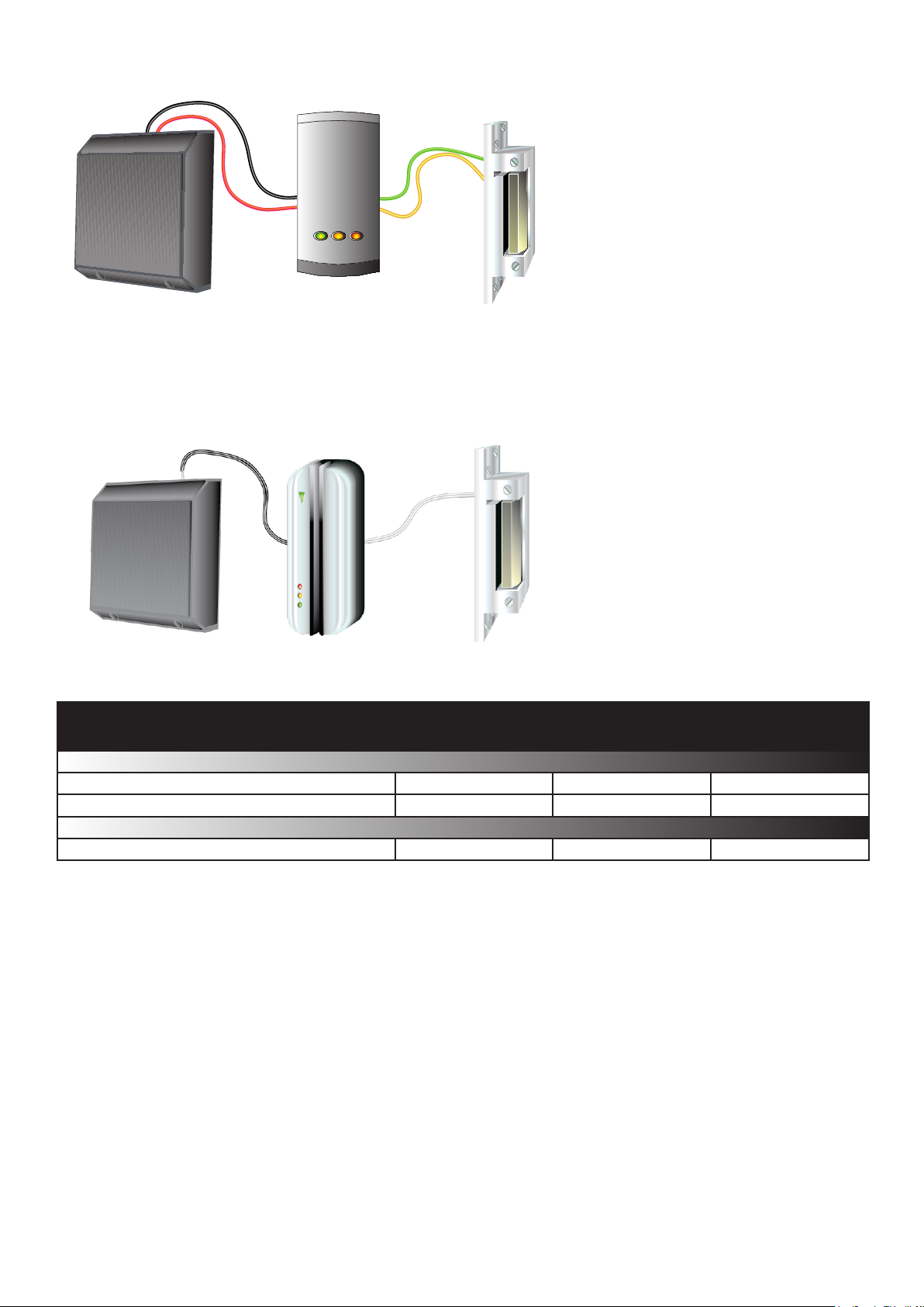
Wiring - Compact Series - 2005
Power supply in plastic housing
This range of Keypad, Proximity and
Cardlock readers uses a pair of White lock
wires to drive up to 500 mA continuous
(750 mA up to 7 seconds). The 12V wire is
identied by being ribbed or striped.
Wiring - Compact Series - 1999
This range of Keypad, Proximity and
Cardlock readers uses Yellow (12V) and
Green (0V switched) wires for the lock.
These compact units can drive up to 1A.
Voltage
Specications
Electrical
Dimensions
Min
Max
Width
Height
Depth
Current
Release
 Loading...