

Page 1

30/01/2012
Ins-30100 Easyprox compact keypad
Technical Support
01273 811011 support@paxton.co.uk
Technical help is available: Monday - Friday from 07:00 - 19:00 (GMT)
Saturday from 09:00 - 13:00 (GMT)
Documentation on all Paxton products can be found on our website - http://www.paxton.co.uk/
Layout
Paxton
Parts list
3
1 2
6
4 5
9
7 8
#
0
*
1
6 7
13
This unit is for indoor use only.
2
8 9
14
3
10 11 12
4
5
1) Front Lock Assembly
2) Rear Lock Assembly
3) Rubber Escutcheon x2
4) Left and Right Handles
5) Battery Pack
6) Tubular Mortice Lock
7) Spindle
8) 8 mm Conversion Sleeve
9) 2 mm Allen Key
10) 8 mm Spanner
11) Strike Plate Backbox
12) Strike Plate
13) Long Mounting Screws x4
14) Short Mounting Screws x4
Tools List
Power Drill
Drill bits 10 mm, 25 mm
Philips screwdriver
Hacksaw for cutting bolts
Hammer / Mallet
Chisel 25 mm
Stanley knife
Adhesive tape
Pencil
Tape measure
8 mm spanner (supplied)
2 mm Allen key (supplied)
Page 1
Page 2
Installing the hardware
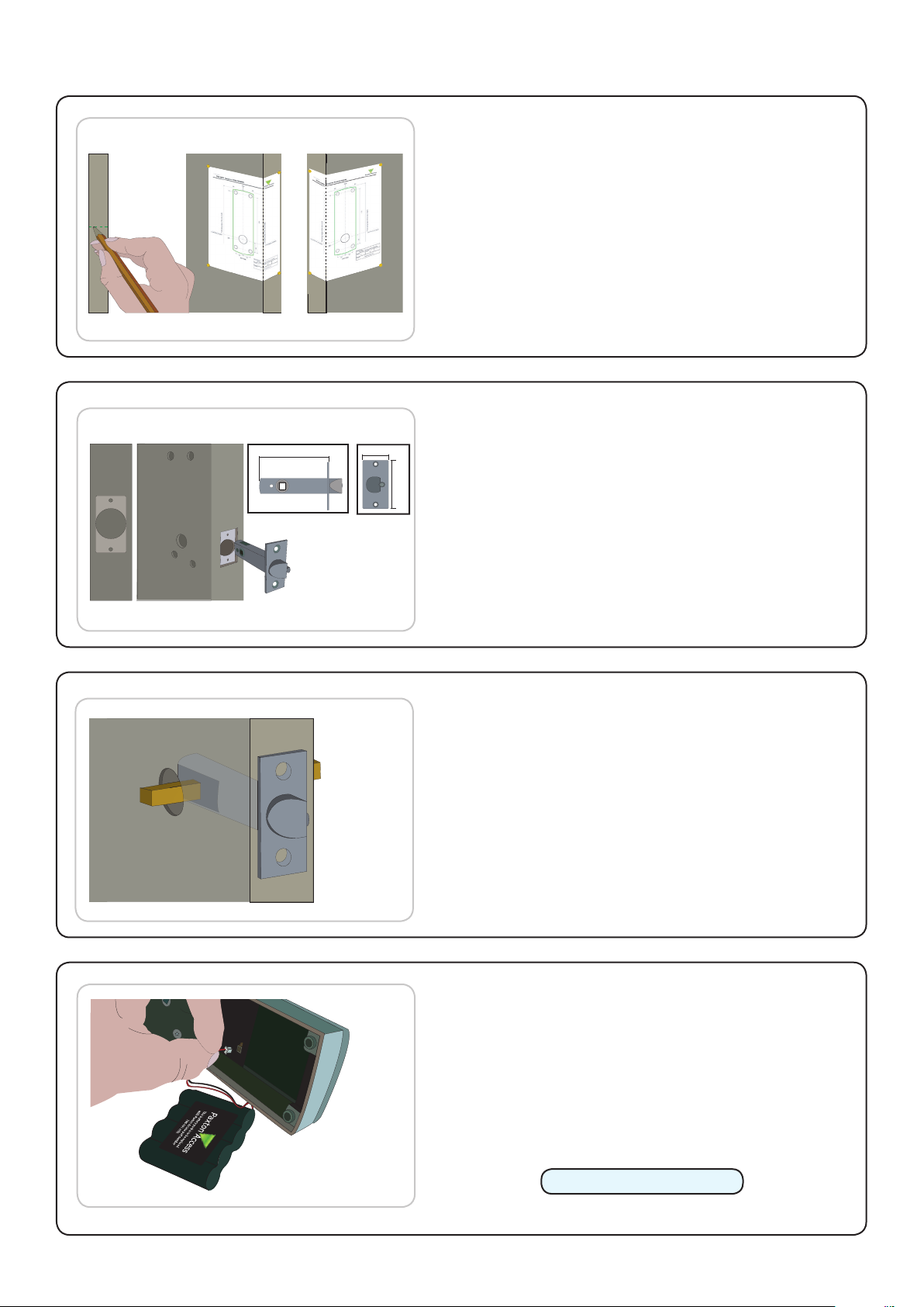
Step 1 - Marking out
Decide on the lock height and mark this on the door.
Fold the template along one dotted line and tape it to the
door with the 'Centreline of Latch' at the required height.
Mark the 4 x 10 mm and 1 x 25 mm holes. Remove the
template, fold along the other dotted line and apply it to
the other side of the door at the same height. Mark the
holes as before.
Step 2 - Drilling
80
25
Drill a 25 mm hole in the door edge at least 80 mm deep
57
to accept the latch.
Drill the 4 x 10 mm holes for the mounting screws and
one 25 mm hole for the spindle. To ensure accuracy
you should drill these holes from both sides of the door
towards the centre. This also avoids the risk of damaging
the door face when the drill breaks through.
Step 3 - Fitting the latch
Slide in the latch and draw around the faceplate.
Remove the latch and score the outline with a Stanley
knife to avoid splitting the wood when chiselling.
Chisel a 3.5 mm rebate allowing a ush t for the latch.
Re-t the latch with the plunger facing away from the
door frame and secure with two latch screws.
Cut the spindle to length (Door thickness + 18 mm) and
slide into the latch.
Step 4 - Enrolment
Remove the access plate at the rear of the unit by
removing the top standoff screws. Push the battery pack
lead onto the white power plug.
Fit the battery pack and replace the access plate.
To wake up the unit, briey depress the external handle.
The unit will click twice and commence to beep regularly.
The Easyprox must now be initialised.
Please refer to Initialising a new system.
The unit will stop beeping and is now active.
Page 2
Page 3

Step 5 - Mounting on the door
1
2
3
4
5
6
7
8
9
*
0
#
7
Select the short (doors thinner than 45 mm) or long mounting
screws and cut to length if required. (door thickness + 5 mm)
Fit the rubber escutcheons to the front and back plates.
Present the front and rear lock assembly to the door, locating
the square drive in its recess and join the two parts together
with 4 mounting screws.
Step 6 - Fitting the handles
Fit the two handles, positioning the screw holes to the
underside and secure with the grub screws provided.
Check the operation of the lock - See Commissioning checks.
Step 7 - Marking out the strike plate
Fig A Fig B
Fig C Fig D
Fig A - Vertical position of the strike plate - Close the door and mark the top and bottom position of the
latch horizontally across the frame.
Fig B - Horizontal position of the strike plate - Measure the distance from the back edge of the door to
the at face of the latch. (NOT the plunger.)
Fig C - Mark this distance on the frame to show how far back the plate needs to be to hold the door closed.
Fig D - Position the strike plate within these guide lines. Mark the positions of the xing screws and draw
around the 'cut-out' in the strike plate.
Step 8 - Fitting the strike plate
Chisel out a 15 mm aperture to receive the latch bolt.
Fix the strike plate with one latch screw to the surface of the frame.
FROM THE INSIDE: Gently close the door and check that the latch enters the aperture easily with no
additional 'play' in the frame. Small adjustments can be made by moving the plate slightly. When satised,
draw around the outline of the strike plate, remove it. Score around the outline and then cut the rebate to
enable the strike plate to lie ush with the surface.
Fix the strike plate using two latch screws and check the lock operation. Remove the strike plate and
increase the aperture to accept the strike plate backbox. Now re-x the strike plate and check the operation
of the 'anti-shim' plunger and the door.
The unit is now fully operational and should be enrolled as soon as possible to preserve battery life.
Page 3
Page 4
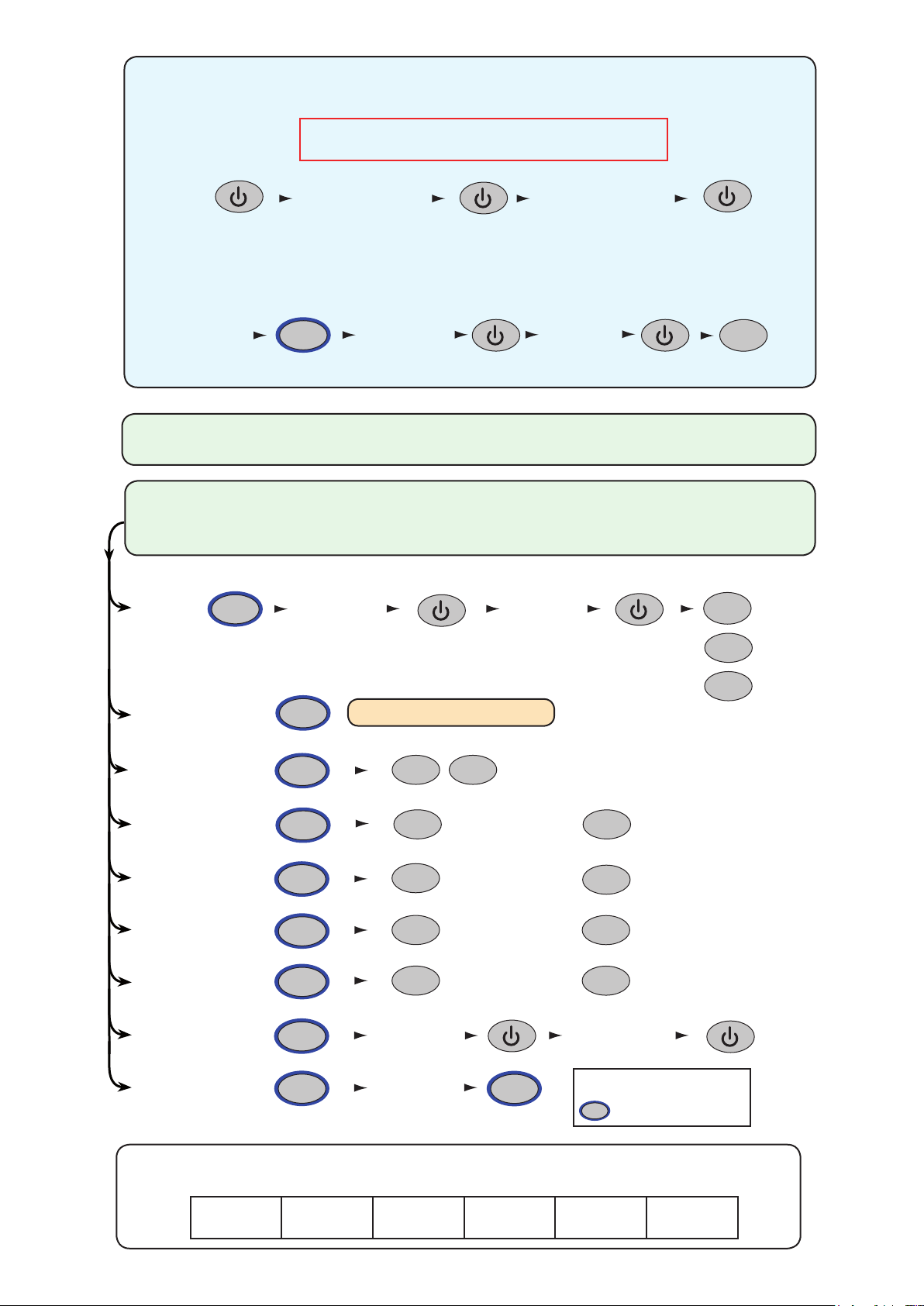
INITIALISING A NEW SYSTEM
Choose a 6 digit Programming Code and load this into the unit as follows:
DO NOT USE 123456 - The default User Code (1234) will open
the door before the Programming Code had been fully entered.
Enter 6 digit
Programming
Code
6 digit
Programming Code
The default user code is now set to 1234
You can now set up the user codes and features using the programming chart.
Example: - Setting a user code to unlock the door under Normal conditions.
8
Hold for 3 secs Normal
Enter user code
4-8 digits
6 digit Programming
Code
Re-enter
user code
TOUCHLOCK MODE
START - Enter the 6 digit Programming Code and hold down a function key
for 3 seconds. - The unit beeps and the LED ashes faster.
Continue the key sequence to set the option - The keypad returns to operating mode.
Set a
user code
8
Enter user code
4-8 digits
Re-enter
user code
4
4
= Normal
Combined Card &
Keypad modes
Door open time
(seconds)
Single or multiple
codes
Silent operation
20 wrong keystrokes
= 60 second lockout
Backlight
Change
Programming Code
Data Reset (except
Programming code)
OR
OR
1
5
2
3
4
0
6
9
See PROXIMITY with TOUCHLOCK
X
2
2
2
2
Enter 6 digit
Programming
Enter 6 digit
Programming
Code
Code
X
One code only
Beep on
OFF
OFF
Enter time in seconds
(default = 03, max = 60)
9
OR
OR
OR
OR
6
6
6
6
Re-enter 6 digit
Programming
Code
Function keys
Multiple codes allowed
Silent
ON
ON
= Hold down for 3 secs
6
2
= Toggle
= Delete
This box can be used to write down the Programming Code for future reference.
Ensure that this information is stored in a secure place.
Page 4
Page 5

PROXIMITY with TOUCHLOCK mode
1. At installation, present this card to the
reader to
validate the to
kens in this pack
2. To re-validate a user to
ken present this
enrolment card to the reader followed
by the
user token
Paxton Access
FUNCTION CARD
enrolment card
More info:
http://paxton.info/74
1. At installation, present this card to the
reader to
validate the to
kens in this pack
2. To re-validate a user to
ken present this
enrolment card to the reader followed
by the
user token
Paxton Access
FUNCTION CARD
enrolment card
More info:
http://paxton.info/74
(i) The unit must rst be initialised in TOUCHLOCK mode: See TOUCHLOCK section
(ii) Set up the required operating mode, as follows:
Enter 6 digit
Programming
Code
1
Hold for 3 secs
1
Card plus PIN Card or CodeCard plus Code
OR OR
2
3
(iii) Present enrolment card
Enrolment card
PROXIMITY
enrolment card
1. At installation, present this
card to the reader to validate
the tokens in this pack.
2. To re-validate a user token,
present this enrolment card
to the reader followed by the
user token.
All tokens will now be validated.
Tokens can now be issued to users
Adding an additional Proximity card pack. You need to be in possession of a valid enrolment card for this
system. Present this enrolment card to the reader and the Amber LED will ash with the Green & Red LED's
off. Present the Enrolment card from the new card pack. The reader will beep and all LED's will be lit. The
additional cards will now be valid. Repeat this with each reader and with any additional card packs. Any valid
enrolment card can be used to add further packs. If an incorrect enrolment card is used to start the process,
the Red LED will be lit and the reader will produce a squeak sound as it rejects the card.
To bar a user:
Present the user's shadow card
The user card is now barred
A user can be re-validated by showing the enrolment card followed
by the user card or re-entered if used in Card+PIN mode.
Card plus Code. Access is granted by presenting a valid token and then entering a valid user code.
Card or Code. Access is granted by presenting a valid token or entering a valid user code.
Touchlock programming - Function 2 to enable multiple user codes, Function 8 to add user codes. (4 digits)
Card plus PIN. A card requires a 4 digit PIN to be assigned to it before it will work, as follows:
Present
enrolment card
Flashing Amber LED
PROXIMITY
enrolment card
1. At installation, present this
card to the reader to validate
the tokens in this pack.
2. To re-validate a user token,
present this enrolment card
to the reader followed by the
user token.
Present
user card
Enter PIN
Flashing Amber/Green LED
Re-Enter PIN
Flashing Amber/Green (faster) LED
If Card plus PIN is selected, the total number of users that may be enrolled
is limited to the maximum number of PIN's. (see Specication table)
IMPORTANT: Before presenting a PROXIMITY card to the reader, you must rst press the
POWER - - key or briey depress the handle.
The reader is then active for 5 seconds. This time limit helps to ensure maximum battery life.
Page 5
Page 6

Enrolment Card - must be presented when the system is
1. At installation, present this card to the
reader to validate the tokens in this pack
2. To re-validate a user token present this
enrolment card to the reader followed by the
user token
FUNCTION CARD
enrolment card
1. At installation, present this card to the
reader to validate the tokens in this pack
2. To re-validate a user token present this
enrolment card to the reader followed by the
user token
FUNCTION CARD
enrolment card
1. At installation, present this card to the
reader to validate the tokens in this pack
2. To re-validate a user token present this
enrolment card to the reader followed by the
user token
FUNCTION CARD
enrolment card
More info: http://paxton.info/74
1. At installation, present this card to the
reader to validate the tokens in this pack
2. To re-validate a user token present this
enrolment card to the reader followed by the
user token
FUNCTION CARD
enrolment card
This card is used with systems where a fail open
electric release is used for the safe operation in the
event of a fire. Present the
card to the reader to
drive a fail open release or a maglock. Present the
card again to revert to the fail closed operation
FUNCTION CARD
fail open release
This card is used with systems where a fail open
electric release is u
sed for the safe operation in the
event of a fire. Prese
nt the card to the reader to
drive a fail open release or a maglock. Present the
card again to revert to the fail closed operation
FUNCTION CARD
fail open release
rst powered on
1
1. Take the enrolment card from the new pack of user cards.
2. Present the enrolment card to the reader.
3. The reader will beep as the enrolment card is acknowledged.
4. All cards in the pack are now valid. The enrolment card can now be returned to it's pack.
2 3 4
3
1 2
6
4 5
9
7 8
#
0
*
PROXIMITY
enrolment card
1. At installation, present this
card to the reader to validate
the tokens in this pack.
2. To re-validate a user token,
present this enrolment card
to the reader followed by the
user token.
3
1 2
6
4 5
9
7 8
#
0
*
BEEP!
BEEP!
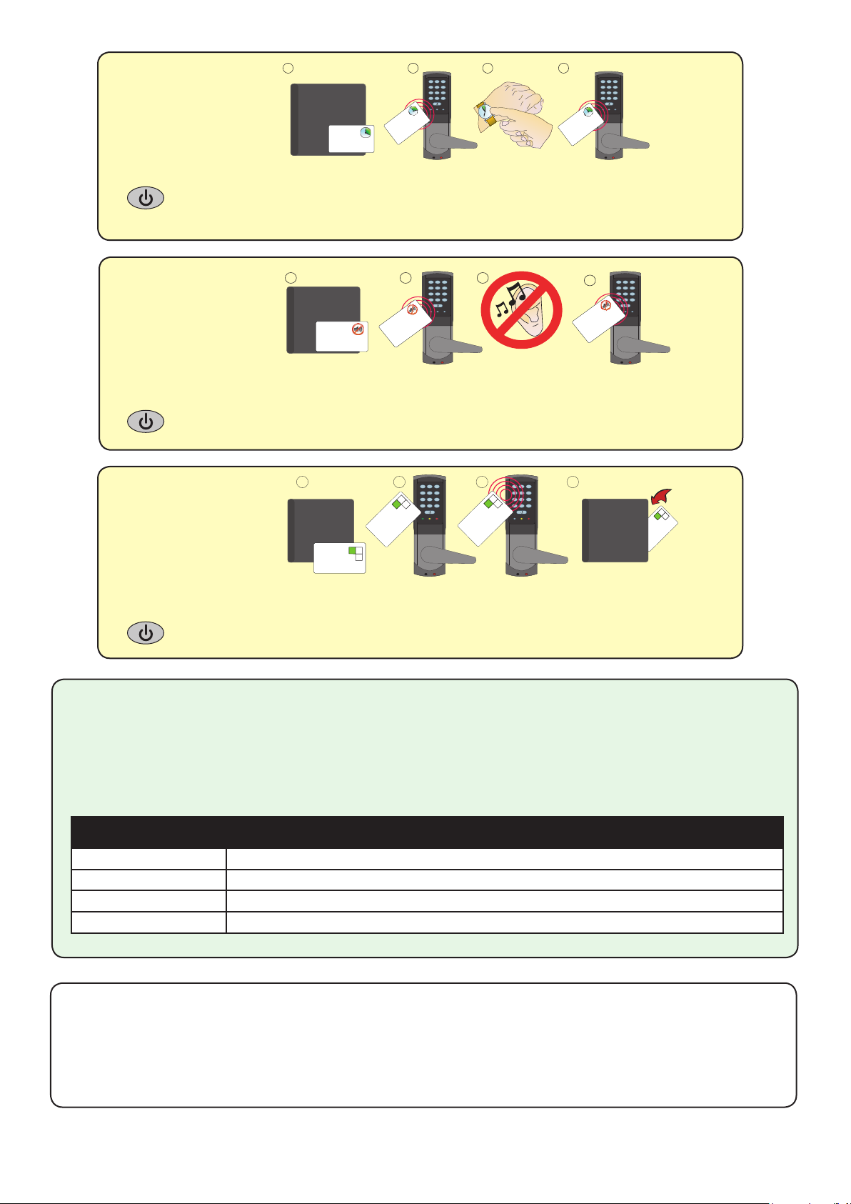
Issuing tokens
1
2
3
1. Across each double page there are 'pairs' of cards - a 'User card' and a corresponding 'Shadow card'.
2. Write the name of the user on the shadow card.
3. Issue the matching user card to the user.
4. Keep the card pack containing the shadow cards in a safe place.
4
Bar a user
1 2 3
3
1 2
6
4 5
9
7 8
#
0
*
1. When a card is lost or stolen it is important to bar the card from your system to avoid unauthorized access.
2. To bar a card or token take it's corresponding shadow card from the card pack.
3. Present the shadow card to the reader. This will remove the lost card or token from your system.
4. A barred card can re-validated by presenting the enrolment card followed by the user card to the reader.
Door held open
1 2 3 4
3
1 2
6
4 5
9
7 8
#
0
*
BEEP!
FUNCTION CARD
fail open release
This card is used with systems where a fail open
electric release is used for the safe operation in the
event of a fire. Present the card to the reader to
drive a fail open release or a maglock. Present the
card again to revert to the fail closed operation
The 'Fail open release card' is used to hold the door open.
1. Take the fail open release function card from the starter pack.
2. Present the card to the reader. The reader will give a short beep.
3. The door is now set to be permanently unlocked.
4. To relock the door, present the card again, the reader will beep once and return to normal operation.
A button on the inside allows the internal handle to be held in the unlocked position.
3
1 2
6
4 5
BEEP!
9
7 8
#
0
*
Page 6
Page 7
Door open time
1 2
3
4 5
6
7 8
9
*
0
#
1 2
3
4 5
6
7 8
9
*
0
#
1 2 3
4
BEEP!
BEEP!
BEEP!
FUNCTION CARD
silent operation
Present this card to silence the beeping noises
made by the reader. Present this card again to
re-enable the beeping noises
FUNCTION CARD
silent operation
Present this card to silence the beeping noises
made by the reader. Present this card again to
re-enable the beeping noises
FUNCTION CARD
silent operation
Present this card to silence the beeping noises
made by the reader. Present this card again to
re-enable the beeping noises
1. Take the 'door open time' card from the starter pack.
2. Present the card to the reader. The reader will start beeping.
3. Wait for the required period you wish the door to remain open.
4. Present the card again at the end of the period to set the open time. The beeping will stop.
Silent operation
card
1. Take the silent operation function card from the starter pack.
2. Present the card to the reader. The reader will beep.
3. The reader is now in silent operation mode.
4. Present the card again to disable silent operation mode. The reader will beep twice.
1 2 3 4
3
1 2
6
4 5
9
7 8
#
0
*
BEEP!
BEEP!
FUNCTION CARD
door open time card
The period that the door is unlocked for when a
valid token is presented is set as follows:
1. Present this card
2. Wait for the required period
3. Present this card again, the beeping will stop
FUNCTION CARD
door open time card
The period that the door is unlocked for when a
valid token is presented is set as follows:
1. Present this card
2. Wait for the required period
3. Present this card again, the beeping will stop
FUNCTION CARD
door open time card
The period that the door is unlocked for when a
valid token is presented is set as follows:
1. Present this card
2. Wait for the required period
3. Present this card again, the beeping will stop
3
1 2
6
4 5
9
7 8
#
0
*
Colour zone
cards
1
Green zone card
Swiping or presenting this card to the
reader will turn off the green LED.
Green cards will not be allowed
access when the reader's LED is off.
Swipe or present the card again to
turn on the green LED. Zone cards
enable access to parts of the building
to be restricted to certain card colours.
2
3
1 2
6
4 5
9
7 8
#
0
*
Green zone card
Swiping or presenting this card to the
reader will turn off the green LED.
Green cards will not be allowed
access when the reader's LED is off.
Swipe or present the card again to
turn on the green LED. Zone cards
enable access to parts of the building
3
to be restricted to certain card colours.
1 2
4 5
7 8
0
*
4
3
6
9
#
BEEP!
BEEP!
Green zone card
Swiping or presenting this card to the
reader will turn off the green LED.
Green cards will not be allowed
access when the reader's LED is off.
Swipe or present the card again to
turn on the green LED. Zone cards
enable access to parts of the building
to be restricted to certain card colours.
1. You require a function card pack.
2. To bar green users from this door present the green zone card.
3. The LED's will briey display the colour zones that are still active.
4. To reverse this process, present the green zone card again.
This may also be done with red and amber zone cards.
Normal Operation
The external handle is only engaged once access has been granted. The inside handle is always engaged.
A valid user card will cause the Green LED to ash briey and the handle will then engage. This time period
can be changed with the 'door open time' card but should be kept to a minimum to preserve battery life.
LED indications
Green ash
Red ash + low beep
Amber constant ashing
Red constant ashing
A valid user card has been presented and the handle is engaged
An invalid user card has been presented - No access granted
A valid user card has been presented - the handle is not horizontal and so the latch cannot release
The handle is being held down - The latch cannot relock
Alarm Sounder
The alarm is activated when the door fails to re-lock itself. The alarm will sound for 60 seconds during
which time the unit will try to lock the door once every 10 seconds. After 60 seconds the unit will then
shut down. When the unit is woken up, it will immediately try to lock the door. If it fails, the alarm cycle
will start again. Failure to relock will substantially reduce battery life.
Page 7
Page 8

Commissioning checks
With the product xed securely to the door:
1) Hold the door unlocked by presenting the fail open release card.
2) Check that the handles are running smoothly. This is best done by depressing the handle all the
way to the bottom and then releasing it as slowly as possible. If the handle is left behind at any
point, it is likely that the product has not been installed squarely enough. Check the handle on
both sides of the door.
3) If your nger is able to leave the handle, remove the unit from the door (or slacken the four
mounting screws) and see if the problem goes away. If it does, the installation onto the door is at
fault and the drilling of the mounting holes should be checked for alignment.
4) Return the door to normal operation by presenting the fail open release card again.
This test conrms the correct and free operation of the mechanical lock and also ensures that the
electronic circuits will shut down correctly preserving battery life.
Low battery warning
When the battery voltage falls below 4V, the user will see a delay between the card being read and
access being granted. This delay provides a warning that the battery pack should be replaced.
The warning delay starts at 2 seconds, increasing up to 10 seconds as the battery discharges with use.
The door open time should be kept to a minimum to preserve battery life.
Recovery from a at battery
Should the battery pack become discharged, the latch will no longer
function. This could be in the locked or unlocked state.
Holding a PP3 9V battery up to the contacts on the bottom of the unit will
allow the circuitry to operate normally.
A valid user card can then be used to open the door to access the batteries.
Battery replacement
1. Remove the unit from the door by removing the 4 securing screws on the rear lock assembly.
2. Remove the top two standoff screws - Fig 1.
3. Remove the access plate to reveal the battery pack. - Fig 2.
4. Unplug the lead and replace the pack with a new Paxton battery pack. - Fig 3.
(The unit will retain its settings and should not be manually reset).
5. Ret the access plate and secure.
6. Ret the unit to the door.
+ve-ve
Fig 1
Fig 2
Fig 3
Page 8
Page 9

Full System Reset
The unit is returned to its Factory settings
and will require initialising again.
There are two possible methods:
1. Remove Easyprox from the door by removing the 4 securing screws on the rear lock assembly.
2. Remove the plastic access plate at the rear of the front lock assembly. (top two standoff screws)
3. Locate the reset push button at the lower right corner of the circuit board.
4. Hold the button down and press the power button on the front of the keypad. - The unit will beep 3 times.
5. Press and release the reset button 4 more times - The unit will beep and display a ashing GREEN LED.
6. Remove and replace the battery plug. - The unit will beep and display a ashing AMBER LED.
- IT NOW REQUIRES RE-ENROLLING.
7. Replace the access plate.
8. Ret the lock to the door with the 4 mounting screws.
- OR -
1. Wake up the unit by pressing the power button. 4. Present Enrolment card again.
2. Present Enrolment card. 5. Present Door open time card twice.
3. Present Door open time card twice. 6. WAIT FOR 5 SECONDS
Features
Number of Users
Number of Card Packs
Number of PIN's
Door open time
Access levels (Colour Zones)
Silent operation
Environment
Operating temperature - Battery limits
Battery Type
Typical Battery Life
Waterproof
Vandal resistance
Read Range
Dimensions
Reader/Keypad module (required space on door)
Total outside dimensions (includes handle clearance)
The declaration of conformity is available on request. Contact details are provided at: http://paxton.info/596
Specications
Min
1
1
1 sec
1 3
Min
0 °C 55 °C
Token
50 mm 30 mm
Width
60 mm 194 mm
150 mm 194 mm
Max
10,000
100
5,000
60 sec
Max
30,000 operations
Keyfob
Height
Yes
Paxton Battery Pack
No
Low
Depth
30 mm
72 mm
Page 9
 Loading...