

Page 1
14/11/2011
Ins-30044 Demonstration Case - TCP/IP
Paxton
Technical Support
01273 811011
Technical help is available: Monday - Friday from 07:00 - 19:00 (GMT)
Saturday from 09:00 - 13:00 (GMT)
Documentation on all Paxton products can be found on our website - http://www.paxton.co.uk/
support@paxton.co.uk
Quickstart guide
The demonstration case contains the hardware required to show all the functions of an operating Net2 system.
Reader 1 is a KP unit that can be used to demonstrate proximity and keypad functions or a combination of both
(e.g. Card + PIN).
Plug the mains cable into the connection as shown on the diagram. Power on the unit by means of the switch and
the power LED should illuminate. The ACU should display 5V, 12V and a ashing OK LED.
Connect your PC to the LAN port via a crossover cable (supplied) and then set up the ethernet connection as per
the instructions on page 2.
Documentation
A full range of application notes and tutorials are available to guide you through the set-up and operation of the
Net2 system. - Just click on the Documentation icon on the Net2 welcome screen for the complete list.
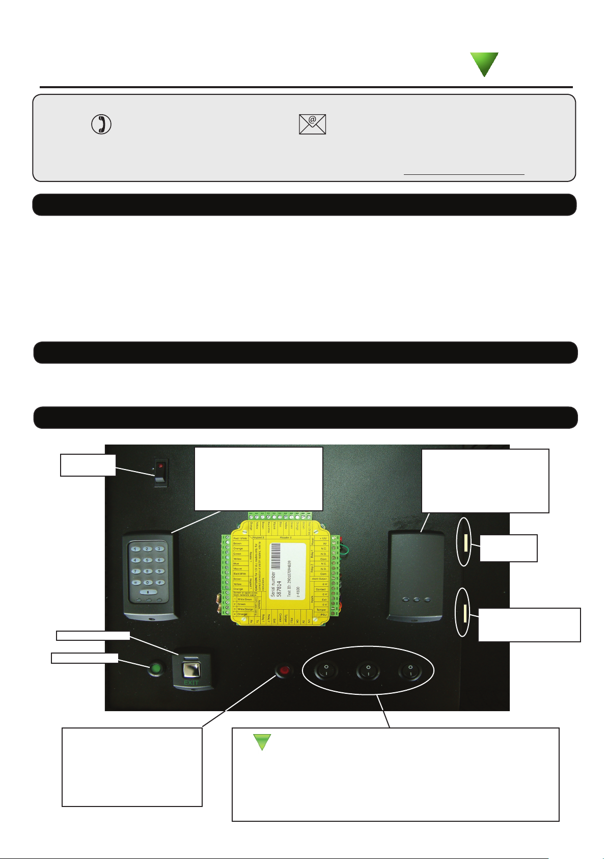
Layout
On/Off
Switch
Exit button
Power LED
K P Reader
Reader 1 is a combined
keypad / proximity unit
P series reader
Reader 2 is a standard
P50 reader
AC Mains
Connection
TCP/IP LAN
(crossover cable
required)
QAlarm LED
The LED displays the condition
of the General Alarm Output.
(An external alarm would be
ringing while the LED is On)
Input Functions
• Contact: The door contact input (Closed when door in frame)
• Tamper: Simulates a signal from a tamper switch (Enclosure opened)
• PSU: Simulates a Mains Failure signal from a monitored power supply.
Page 2
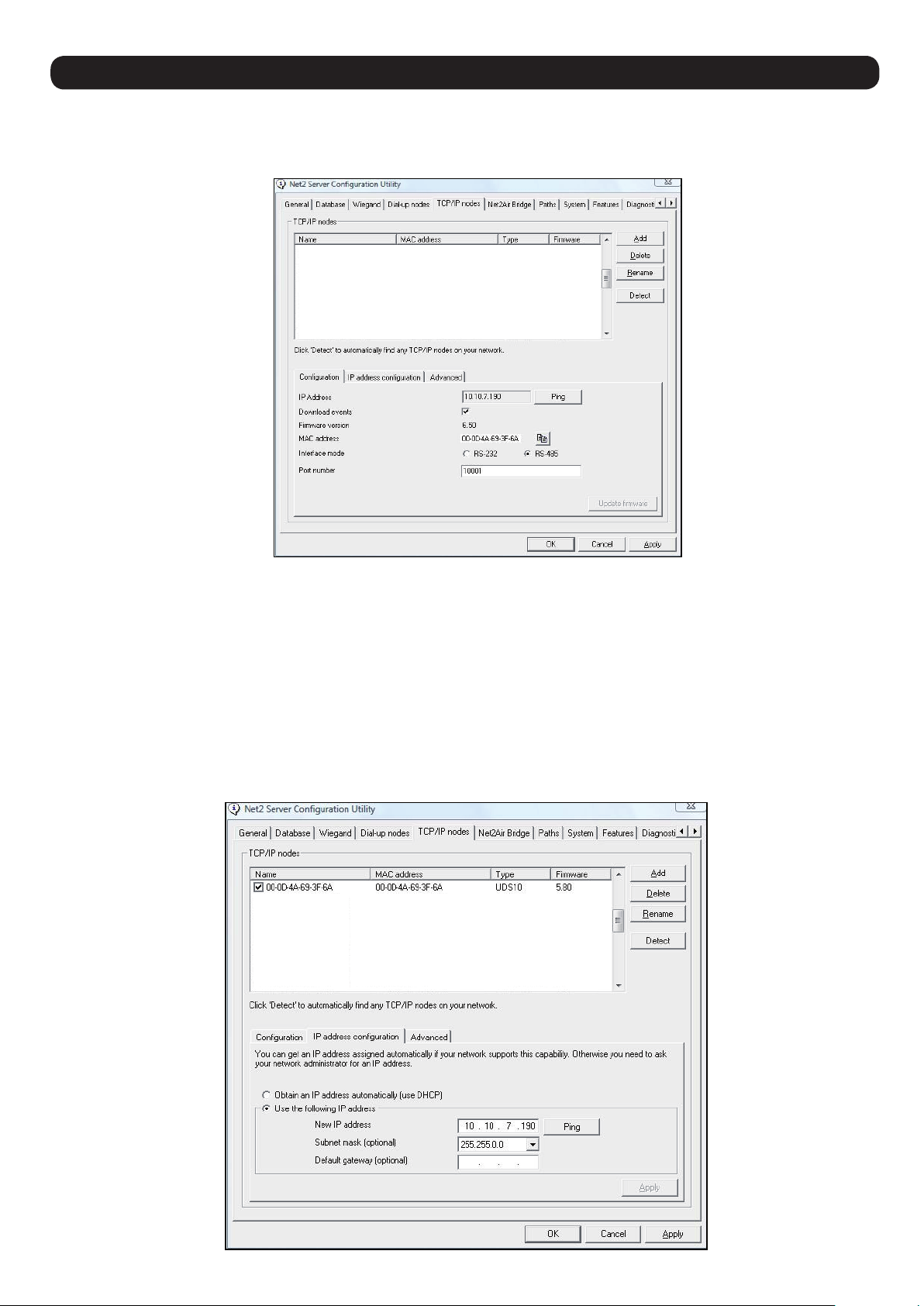
Connecting to a TCP/IP interface
Install the Net2 software on the PC. Connect the unit to the PC via a Network cable.
Run the Net2 Server Conguration Utility (Start/Programs/Net2) and select TCP/IP nodes.
Click on "Detect" the MAC address of the Ethernet interface will appear in the table. You should then go to the "IP
address conguration" tab and assign the IP address.
You can set up a new IP for the interface but if this is not in the same range as the PC, the device will no longer
respond until you connect to the device with a PC that is in the same IP range.
Some rewall/virus software or other wireless hardware can block the IP detection process. Disable these and try
to detect the interface again. Please contact Technical Support if you require further advice.
*The MAC address can be found on a label in the case and starts 00-xx-xx-xx
Page 3

Software conguration
• Run the Net2 software.
• Check that the ACU has been detected by looking in the Doors screen. The rmware in the ACU's will be
automatically updated to the same revision as the PC. Do not make any changes to the software during this phase.
• Once this has nished, each ACU must be congured (as below)
Door name: Name the ACU.
Door open time: Set the door open time.
Unlock the Door during: Permanently unlocks the door while
this timezone is active. - Should be set to 'At No Time' for
normal user operation.
Reader 1: Settings for Reader 1 and Keypad 1 on the ACU.
Reader 2: Settings for Reader 2 and Keypad 2 on the ACU.
Alarm: Contains settings for the different types of alarm.
Codes: Valid codes can be viewed, added and removed.
(Can only be viewed when a keypad is active).
Events: Shows the events for the control unit selected.
Name: Each reader can be named individually if required.
Reader type: Set the reader type, if applicable.
Keypad type: Set the keypad type, if applicable.
Token data format: Select the data type being used on the
system. (New formats can be created).
Reader operating mode: Set the operating mode.
Timed operating modes: A different operating mode can be
congured within a time window.
Reader action: Set the action required when access is granted.
Page 4

Specications
Software
Number of Cards
Number of PIN's
Access Levels
Time Zones
Individual time periods per zone
Maximum door open time
Number of Codes
Hardware
Doors per ACU
Reader ports per ACU
Readers per port
Keypads per port
ACU per data line
Data lines per PC
Data retention after total power loss
Events stored in ACU with no server connection
PC Installation
Minimum Requirements
10,000
10,000
250
64
2,000
5,000 secs
50
1
2
2
2
200
50
9 hours
2,454
http://paxton.info/720
Statement of Conformity
Paxton Access Ltd hereby declares that this product is in conformity with all the essential requirements of Directive
1999/5/EC. This equipment is intended for use in all EU and EFTA countries and all other countries worldwide.
The declaration of conformity is available on request. Contact details are provided at: http://paxton.info/596
 Loading...