

Page 1
redaeR
:n oitu
a
C yl
nos
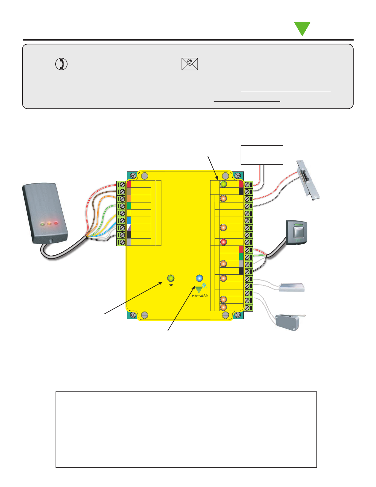
redaerC D V21roF
+V out
Red LED
Amber LED
Green LED
Data/D0
Clock/D1
Media Detect
0V
Entry
12V
12V Lock
0V
0V
N.C.
N.O.
COM
Alarm
12V
Green LED
Exit
0V
Contact
0V
0V
Tamper
PSU
0V
nott
u Btix
E
yaleR
kcoL
stuptuO
stupnI
rewoP
tcatnoC
repmaT/USP
Net2 nano
01/28/2013
Ins-40075-US Net2 nano control unit - UL
Technical Support
Paxton
Documentation on all Paxton products can be found on our web site - http://www.paxton-access.com/
This access control unit uses wireless communication. It is recommended that a Net2Air
Reader/keypad
1.800.672.7298
supportUS@paxton-access.com
Technical help is available: Monday - Friday from 02:00 AM - 8:00 PM (EST)
For instructions in alternative languages - http://paxton.info/1000
site surveyor is used to determine the best position for the bridge and control units.
This wireless unit requires a Net2Air bridge to communicate with the server PC.
Diagnostic LEDs
12V DC
power supply
Lock release
Not connected
*
This is the heartbeat of the
system and should pulse
regularly. This indicates that
the processor is functioning.
A new unit requires approximately 30 seconds after initial power up to self congure.
The unit will not operate correctly until this function has completed.
LED indications
12V (Green) - Power LED.
Lock (Orange) - The 12V lock output is energised.
Relay (Orange) - The relay is energised - (NO/COM contacts are closed).
Alarm (Red) - 12V Alarm output is active.
Exit (Orange) - The exit button contacts are closed.
Contact (Orange) - The door contacts are closed.
Tamper (Orange) - The tamper contacts are closed.
PSU (Orange) - The PSU contacts are closed.
Net2Air (Blue) - Net2Air interface Tx/Rx activity.
OK (Green ash) - The internal software is running.
*
Net2Air wireless activity (Tx/Rx) - Blue
During this time the OK LED will not be ashing.
Exit button
(push to make)
Door contact switch
(held closed by door)
Tamper switch
Page1
Page 2
Net2Air wireless communication
Net2Air wireless control units are fully compatible with the hard wired Net2 range but there are several important
dierences that need to be understood before installing wireless equipment. The most important of these is the
location of the control units and their bridge components.
These principles are therefore explained rst before we move on to the control unit itself.
The access control unit connects to the Net2 software running on the PC using Paxton Net2Air proprietary wireless
technology. A Net2Air bridge enables communication from the Net2 software to the Paxton wireless products.
Radio signals do not always behave as you might expect. For example, a cell phone that displays a full signal on
one part of the site will lose signal completely only a few feet away. These problems can be addressed by using the
Net2 site surveyor kit (690-200-US)
See also: XAN1095 - Net2 nano - How does it work? < http://paxton.info/974 >
X AN1096 - How to plan a Net2 nano installation < http://paxton.info/975 >
X Ins-30096-US - Net2Air site surveyor < http://paxton.info/1193 >
Radio frequency
This product should not be installed within 10 feet of other wireless equipment operating on a 2.4Ghz frequency.
To ensure optimum performance other wireless networks should avoid WiFi channels 11, 12 and 13 to reduce the
possibility of interference.
A Net2 nano ACU or a Hands free interface cannot be installed in a Metal cabinet as this would block the RF signal
used for the Net2Air wireless technology.
Options
Part number Description
654-943-US Net2 nano 1 door access control unit
654-549-US Net2 nano 1 door ACU in plastic housing
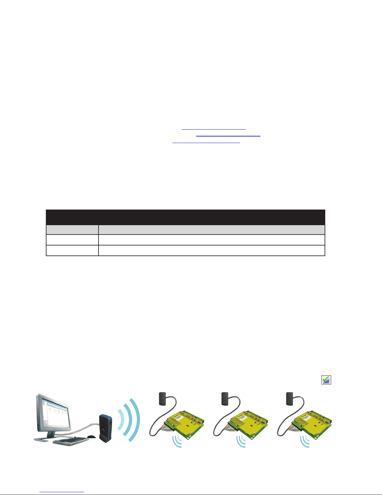
Net2 nano PC / server operation
Data transfer with wireless technology requires far more control and error checking than with a hard wired data
line connection. Net2 classic runs with a server that originates and controls all the communications on the data
line. This would not be ecient in a wireless environment.
We therefore give the Nano controller the active role. Each Nano is always active and transmits data bursts
(including a regular Heartbeat) every few seconds. The Net2 server then acts upon these requests for service.
The PC requires at least one Net2Air bridge to communicate with a Nano. This can be a local Net2Air USB bridge
(only one per system) and/or multiple Net2Air Ethernet bridge units connected to the PC via a TCP/IP connection.
There is NO Net2 nano detection function. It is recognised that there could be security issues if the wireless
units were detectable from outside the site. During installation, a Nano unit binds with a Net2Air bridge which will
then only talk to registered units. The Server conguration utility also has an ' Enable commissioning' mode which
can be turned o to inhibit Nano units being added.
An entry is then made on the Doors screen and a special icon is used to denote the wireless connection.
Net2 Server
Reader
The reader's default indication has all the LED's on. Access granted is denoted with a single ashing Green LED
Access Denied is a single ashing Red LED.
Control unit
.
Page
2
Page 3
Mounting
Cable type
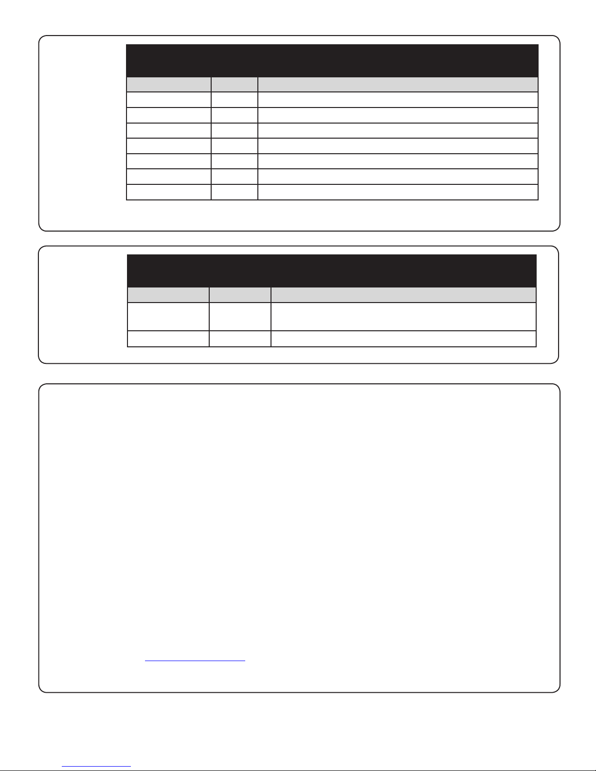
Parts kits
Part number Qty Description
Fitting Kit fk1-095 3 35mm wall plugs
3 8g x 1.5 pozi twin woodscrew
1 M4 x 20 pozi pan machine screw
5 Cable tie
4 Cable clip
1 Diode 1N4001
1 M4 Rubber washer
This product is not suitable for retail sale. All warranties are invalid if this product
is not installed by a trained technician.
Cable specication
Use Max length Type
Reader / Keypad 500 feet
8 core, shielded - Belden 9538, Alpha 1298C (22AWG) General Cable
C0744A / C0745A (22AWG)
Input / Output 100 yds 2 conductor - Alpha 1172C (22AWG) or equivalent
Control unit installation
This unit is for Indoor use only
The ACU shall be installed within the protected premises as both the power and lock wiring is present at the PCB.
A Tamper alarm input is provided on the PCB - See Input/Output Wiring
Where the ACU is being installed within a plastic enclosure, the hub must be connected to the conduit before it is
connected to the plastic enclose. This is to eliminate the potential of any excessive torque loading being applied
to the plastic enclosure during installation.
This housing should be xed to the surface with suitable fasteners; screws and wall plugs are provided for this in
the tting kit. Also provided are cable ties to secure the cabling and a smaller securing screw for the lid.
Wire the components to the Access Control Unit (ACU) as shown on the rst page.
Press the exit button or in the absence of an exit button, short the 0V and exit terminals together.
The congured lock output LED will come on and the lock should release.
The unit will continue to operate in a 'standalone' mode if the PC is shut down. Any Events that occur during this
period are stored in the unit and the PC is updated when it comes back on line.
PC installation
The current specication for compatible PC hardware, network and operating systems is available on our website
at the following link: http://paxton.info/720
Page3
Page 4

Software installation
The Net2 software should be loaded on the controlling PC with at least one Net2Air bridge installed.
Full documentation is supplied with the Net2Air bridge unit and also from the website as follows:
Only ONE Net2Air USB bridge may be used per system. Multiple Net2Air Ethernet bridges may also be congured.
XAN1051 - Installing Net2 software < http://paxton.info/1520 >
XIns-40084-US Net2Air USB bridge < http://paxton.info/1453 >
XIns-40085-US Net2Air Ethernet bridge < http://paxton.info/1192 >
Page
4
Page 5

Enrolling a Net2 nano
A Nano must rst bind to a Net2Air bridge before it will enroll itself onto the Net2 system. The term 'bind' is used
to denote the xed relationship between a Nano and its bridge.
Create a user record in the database and assign a Net2 token to the user. If you are not using PROXIMITY tokens
you should still create the user record and assign a token number (Not a PIN) of your choice. These records can
be deleted after the installation is complete.
Connect a PROXIMITY reader to the Nano and then present the same user token previously assigned. (If you are
enrolling a Keypad only unit, enter the token number on the keypad followed by * ) The Nano will then transmit
the token number and wait for a response from a bridge.
If more than one bridge replies, the Nano checks the signal strength and selects the strongest bridge to
communicate with. The Net2 software conrms that the token number is in the database and if so registers this
Net2 nano/bridge binding.
System checks
Present a token at each reader. An event for each read should appear in the Events screen.
Change the default password for the System Engineer.
Set up other operators if required.
Set up time zones.
Set up access levels.
Users can be added & assigned to the required access level.
Departments can be created if required.
The Net2 CD can assist here with detailed application notes for setting up users and general system operation.
Software conguration
Door name: Name the Door.
Door open time: Set the door open time.
Unlock the Door during: Holds the door unlocked during this
timezone. - Set to 'At No Time' for normal user operation.
Reader: Settings for the Reader and Keypad.
Outputs: Lock, Relay, Alarm. - Selects these outputs to be
used by the Lock, Bell or Alarm functions.
Alarm: Congures the settings for the dierent alarm types.
Codes: Valid keypad codes can be viewed, added and removed
(This tab is only displayed when a keypad is tted)
Events: Shows the events for this control unit only.
Access Rights: Lists users who have access through this door.
Name: Each reader can be named individually if required.
Reader type: Set the reader type, if applicable.
Keypad type: Set the keypad type, if applicable
Reader operating mode: Set the operating mode.
Timed operating modes: A dierent operating
UL compatable readers
mode can be congured within a time window.
Part Type
373-110-US PROXIMITY P75 reader
373-120-US PROXIMITY P75 reader, screw connector
353-110-US PROXIMITY P50 reader
390-747-US PROXIMITY metal reader
390-727-US PROXIMITY metal reader, chrome
390-737-US PROXIMITY metal reader, brass
390-135-US PROXIMITY panel mount reader
Part Type
371-110-US TOUCHLOCK K75 keypad
371-120-US TOUCHLOCK K75 keypad, screw connector
372-110-US TOUCHLOCK K75 stainless steel keypad
372-120-US TOUCHLOCK K75 stainless steel, screw connector
375-110-US PROXIMITY KP75 keypad
375-120-US PROXIMITY KP75 keypad, screw connector
Page5
Page 6

Maintenance
The Net2 nano is designed to take input from Clock and Data readers through its (In/Out) reader port. It can
also be congured for 26bit Wiegand.
It has a Net2Air wireless interface that is used for uploading rmware and user information as well as providing
Event information to the PC on demand.
Following the completed installation of this equipment, no further maintenance or testing is required.
It is advisable to ensure that any third party backup power supplies or recovery procedures are checked
regularly to ensure that the operation of the Paxton system is not compromised.
1 - Short circuiting, mutilation or incineration of the cells must be avoided to prevent one or more of the following
occurrences; Release of toxic materials, release of hydrogen and/or oxygen gas, rise in surface temperature.
2 - If a cell has leaked or vented the control unit must be replaced. The battery is not to be replaced.
Net2 nano reset
The Nano controller holds the address information for the bridge that it has bound with. This will cause
problems if the unit is to be used on another system.
To clear this address information, you need to perform a hardware reset. Link Orange/White on the reader port
and then power cycle the unit.
Make sure that the power is not removed again until after the green OK LED is ashing again. Later versions
of software also ash the reader LED's until the reset process has nished. Remove the Orange/White link.
INPUT / OUTPUT WIRING
The Net2 nano has 3 outputs that can be congured in the Doors screen to perform dierent functions.
This exibility means that a site that requires the Relay output (volt free contacts) for the door function can
congure the Lock output to drive a door bell.
Lock output - This is a transistor 'open drain' output, (not a voltage free contact) that has been designed
to simplify the wiring of the lock. It can be congured to operate in Fail lock, Fail unlock or toggle modes and
removes the need for additional links or diodes normally required when using a relay for output switching.
Relay output - This provides a set of volt free contacts to switch external devices.
Alarm output - This is a transistor driven output that switches to 0V when activated.
Page
6
Page 7

ALARM
12V
12V Lock
0V
0V
N.C.
N.O.
COM
0V
yaleR
kcoL
stuptuO
rewoP
The use of a Fail closed/Secure conguration shall be determined by the local building codes and the local AHJ.
Lock wiring - Lock output (12V DC)
The lock is wired across the 12V Lock and 0V terminals. No diode
12V
re
woP
0V
12V Lock
kco
L
0V
0V
stuptuO
N.C.
yaleR
N.O.
COM
or additonal wiring is required.
Set the 'Lock output' to 'Door lock' and set the release type to
fail locked, fail unlocked, or toggle.
This wiring illustration shows the Lock output congured for the
Door lock function.
See Specication table for Output ratings.
Lock Wiring - Relay output
12V DC power supply
+ -
12V
re
woP
0V
12V Lock
kco
L
0V
0V
stuptuO
N.C.
yaleR
N.O.
COM
Fail closed
This wiring illustration shows the Relay output congured for the Door lock function.
See Specication table for Output ratings.
The lock is wired across 12V and COM. A 0V link is then required to complete the circuit. This will be wired from
0v to NO or NC depending on lock type (Fail Open / Fail Closed)
A diode is supplied which should be tted across 12V and COM (Silver end to 12V ) to protect the relay contacts.
The dry relay contacts can be used to switch the power from an independent lock power supply. Wire the 0V to
NC or NO and the lock to COM; the +VCC supply is wired directly to the lock.
12V
re
woP
0V
12V Lock
kco
L
stuptuO
N.C.
yaleR
N.O.
COM
Fail open
12V
rewoP
0V
12V Lock
0V
0V
kcoL
0V
stuptuO
0V
N.C.
yaleR
N.O.
COM
Lock power supply
-
+
Door lock
Lock with an independent supply
Alarm sounder
The Net2 ACU has a local alarm output. This is a transistor
'open drain' output, (not a volt free contact) that is capable of
switching 1A at 12V DC.
A Lock output, Relay output or Alarm output must be congured
to function as the Alarm output.
This local output can be turned on or o for each type of alarm
and can be congured to sound continuously or intermittently to
distinguish between dierent alarm types.
Page7
Page 8

Door Bell - Relay output
12V
rewoP
0V
12V Lock
kcoL
stuptuO
yaleR
0V
0V
N.C.
N.O.
COM
Pressing the bell button on the keypad will energise the
Door bell output for 1 second.
The Lock output, Relay output or Alarm output must be
congured to function as the Door Bell output.
This wiring illustration shows the Relay output congured
for the Door Bell function.
See Specication table for Output ratings.
Exit button
12V
nott
Green LED
u Btix
Exit
E
0V
When the Exit terminal is shorted to 0V, the ACU will illuminate the Exit LED and activate the lock output for the set
'Door open time'. The lock output will remain active while the short to 0V remains and the reader/exit button Green
LED will ash during this period. More than one exit button can be wired in parallel.
A Lock output, Relay output or Alarm output must be congured to function as the Door Lock output.
Where tted, a 'push to make' button is required.
(See Specication table for ratings)
The Exit LED will be ON when the switch is closed. Button Pushed.
Door Contact
tixE
Exit
0V
stupnI
t
Contact
c
atn
oC
0V
repmaT/USP
0V
Tamper
PSU
A NO switch may be tted so that it is held closed while
the door is shut.
The Contact LED will be ON when the switch is closed.
- Door Closed.
When connected, Net2 will check the door position during
access activity and will raise an Alarm in the event of a
'Door Forced' or 'Door left open' condition.
Tamper switch
tixE
Exit
0V
stupnI
t
Contact
c
atn
oC
0V
repmaT/USP
0V
Tamper
PSU
N.O.
N.C
COM
The ACU supplied in a plastic housing has a 'NO' tamper
switch tted and pre-wired into the circuit board.
The Tamper LED will be ON when the switch is closed.
Net2 will monitor the switch position and will raise an
Alarm in the event of a 'Tamper' condition.
tixE
Exit
0V
stupnI
t
Contact
c
atn
oC
0V
repmaT/USP
0V
Tamper
PSU
COM
N.O.
N.C.
PSU monitoring
The PSU LED will be ON when the NO Relay contacts are
closed. - Power OK.
The Net2 software will monitor the relay contacts and will
raise an Alarm in the event of a 'Power Fail' condition.
Page
8
Page 9

12V
rewoP
0V
12V Lock
kcoL
0V
0V
stuptuO
N.C.
yaleR
N.O.
COM
Break Glass tted
12V
rewoP
0V
12V Lock
kcoL
0V
0V
stuptuO
N.C.
yaleR
N.O.
COM
External Fire Door relay tted
N.O.
COM
Panic hardware
A break glass should be tted, in conjunction with a fail open
release to ensure a reliable egress method in the event of an
emergency. This is tted on the 12V supply wire to the lock and
drops the power ensuring that the lock opens.
The diagram shows how to include the break glass in the Net2
lock wiring circuit.
This wiring illustration shows the Relay output congured for the
Door lock function.
Fire Door Interface
A re alarm system must be used to release all re doors.
External relay contacts are held closed by the re alarm's interface
and will be dropped during an alarm condition. The system is fail
safe as the door will release even if the cable burns through.
This wiring illustration shows the Relay output congured for the
Door lock function.
Product compliance and limitations
To comply as a UL listed installation, the following conditions must apply:The power must be provided via a separate DC supply, a UL Listed Access Control (or Burglar Alarm) Class 2,
Power-Limited, power source capable of 4 hours standby must be employed. This is wired into the 0V and
12/24V terminals and the cable secured with the cable ties provided.
Wiring methods shall be in accordance with the National Electrical Code (ANSI/NFPA70), local codes, and the
authorities having jurisdiction.
Software features and functions have not been evaluated by UL.
Server based functions (Antipassback, Time and Attendance, etc) have not been evaluated by UL and cannot be used
for UL 294 installations.
The use of Wiegand readers and the conguration software has not been evaluated by 'UL'
Wiring: - Where an equivalent cable / wire is used it must be ' UL Listed '
All interconnecting devices must be UL Listed.
Exit buttons - A UL listed 'push to make' button must be used.
Door contact - A UL listed 'Normaly Open' (N.O.) switch must be used.
Tamper alarm - Connect to a UL listed burglar alarm unit for supervision.
Alarm sounder - Connections to this alarm output have not been evaluated by UL for burglar alarm use.
Break glass- A UL listed break glass must be used.
For CAN/ULC-S319 installations, terminals, leads and wiring methods must comply with CSA, C22.1, Canadian
electrical code, Part 1, safety standards for electrical installations.
The use of any add-on, expansion, memory or other module manufactured or supplied by the manufacturer's
representative will invalidate the CAN/ULC-S319 certication.
This device complies with Industry Canada licence-exempt RSS standard(s). Operation is subject to the following
two conditions: (1) this device may not cause interference, and (2) this device must accept any interference,
including interference that may cause undesired operation of the device.
Page9
Page 10

Features
Number of Cards
Number of PIN's
Access Levels
Time Zones
Maximum door open time
Number of Codes
Doors per ACU
Reader ports per ACU
Readers per port
Keypads per port
ACU's per Net2Air bridge - Recommended
Net2Air bridge (data lines) per system
Net2Air wireless range to ACU
Data retention after total power loss
Events stored in ACU with no server connection
Electrical
Input Voltage
Input Current
Relay switchable voltage
Relay switchable current
Dedicated lock output voltage
Dedicated lock output current
Alarm output voltage
Alarm output current
Reader port voltage
Reader port output current
Carrier frequency
Exit button voltage
Exit button current
Environment
Operating temperature - Battery limits
Humidity
Waterproof
Dimensions
Control Unit
Plastic Housing
Specications
Min
1 sec 99,999 sec
1 10
1 100
60 days
Min
120 mA 3 A
11.2V DC 12V DC
11.6V DC 12V DC
10.8V DC 12V DC
11.3V DC 12V DC
Min
0°C (32°F) 55°C (131°F)
85% - Relative humidity
Width
1
4
/8 in 3 1/4 in
7 in 7 in
Max
10,000
10,000
250
64
50
30 yds
3,584
Max
24V DC
2 A
1.1 A
1 A
500 mA
20 mA
Max
Height
1
1
2
2
12V DC
2.405 GHz
No
Depth
7
/8 in
5
/8 in
1
FCC Compliance
This device complies with Part 15 of the FCC Rules. Operation is subject to the following two conditions:
(1) this device may not cause harmful interference, and (2) this device must accept any interference received, including interference that
may cause undesired operation. Changes or modications not expressly approved by the party responsible for compliance could void the
user's authority to operate the equipment.
This equipment must not be co-located with any other transmitter and must be used at a distance in excess of 20cm to the user.
The party that incorporates this equipment into another host device is responsible for verication of the emissions produced by the nal
product and must adhere to the limits specied in FCC Part 15.
Furthermore, a label must be applied to the exterior of the nal product referring to this enclosed module, which states : "Contains
Transmitter Module FCC ID: USE654943" or "Contains FCC ID: USE654943".
Page
10
 Loading...