

Paxton TOUCHLOCK K75, TOUCHLOCK KP75, 351-110-US, 371-110-US, 371-120-US Instruction Manual
...Page 1
01/29/2010
Ins-40077-US TOUCHLOCK K and KP series - UL
Technical Support
1.800.672.7298 supportUS@paxton-access.com
Technical help is available: Monday - Friday from 02:00 AM - 8:00 PM (EST)
Documentation on all Paxton products can be found on our web site - http://www.paxton-access.com/
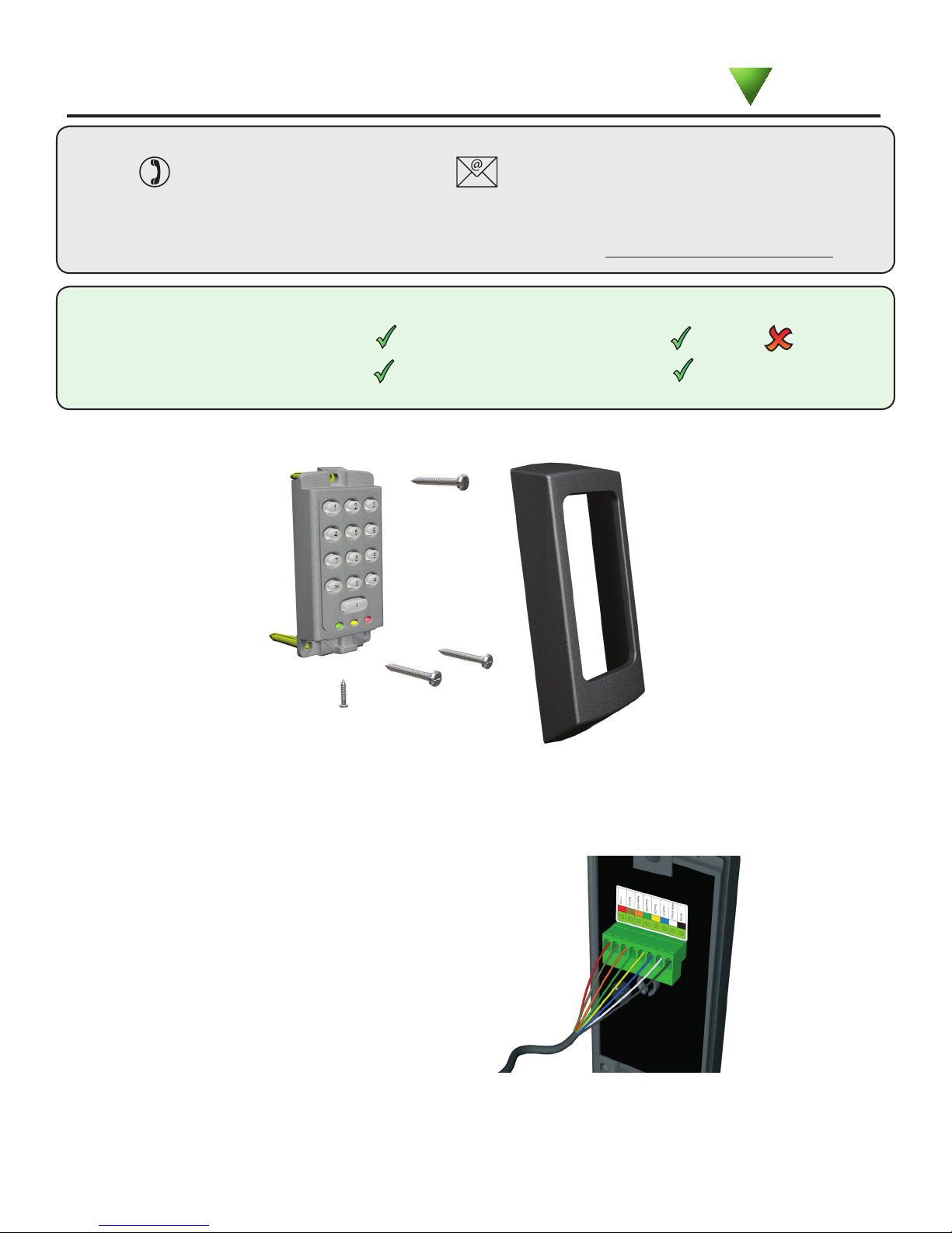
Suitability
Mounting
Security sensitive doors
Wet environments
Mounted on metal surface
Readers mounted together
K KP
Paxton
12 inches
between readers
This keypad is designed to provide a Clock and Data output for Paxton (Net2 / Switch2).
The KP series readers will also read Paxton tokens (Hitag2) and EM4100 tokens.
K75 Screw connector option
NOTE: The unit should be mounted
in conjunction with an electrical
backbox to achieve the required
clearance for the connector.
If an adaptor plate (310-750-US)
is tted, the mountings on the
backbox can also be used.
This unit is for Indoor use only
NOTE: Illustrations in this instruction show the standard keypad.
The Stainless Steel version installs and operates in exactly the same manner.
PAGE 1
Page 2
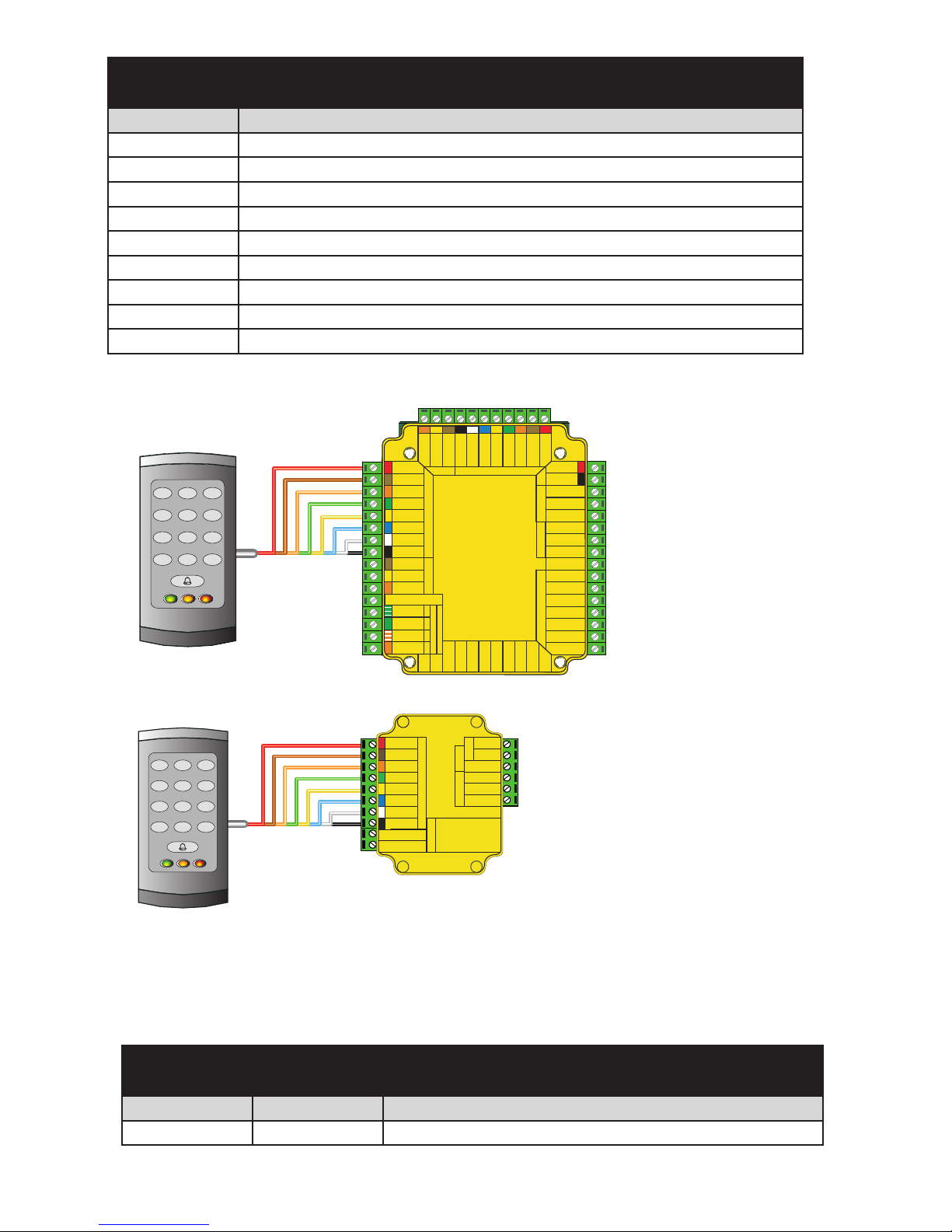
Red 12v dc
Brown
Orange
Green
Yellow
Blue
Mauve
Black/White
Brown
Yellow
Reader 1
Orange
Keypad 1
+12v
0v
N.C.
N.O.
Com
N.C.
N.O.
Com
Alarm Output
0v
Contact
0v
Exit
0v
Tamper
PSU
Rx
Tx
Relay 1
Relay 2
Exit
Contact
Tamper
PSU
OK
5v
12v
Red
Brown
Orange
Green
Yellow
Blue
Mauve
Black/White
Brown
Yellow
Orange
Reader 2
Keypad 2
Power
Relay 1Relay 2Inputs
Network
CAT5 cable coding
White/Green
Green
White/Orange
Orange
1
2
3
4
Screen or spare cores
from network cable
CAUTION: for 12v d.c. readers only. For
correct connection of old 5v readers, refer to
instructions.
Serial number
241821
Test ID: 012345678901
z-1440
3 24898 00000 4
xR
Green
White/Green
1
Screen or spare cores from
network cable
White/Orange
3
Orange
4
K1 redaeR da
pye 1
12V
Alarm Output
R leay 2
N.C.
N.O.
Com
N.C.
N.O.
Com
0 V
0V
Exit
0 V
PSU
0V
Contact
Tamper
R leay 1
V2
1
V
5
KO
T ep
ma
r
tcatnoC
t
i
xE
R leay 1
xT
U
S
P
Keypad 2 Reader 2
stupnI
P ewo r
R le
a
y
2
CA
nidoc
e
lbac
5T g
kr
ow
teN
+V out
Red LED
Amber LED
Green LED
Data/D0
Clock/D1
Media Detect
0V out
Data
Load
Clock
tu
o V+
DEL deR
DEL
re
bmA
DEL neerG
0D/ata
D
1D/kc
olC
tceteD
aideM
tuo V0
ataD
daoL
kcolC
Net2
2
1
2 3
4 5 6
7 8 9
0 #
*
Wiring
Options
Part number Description
351-110-US TOUCHLOCK K50 keypad
371-110-US TOUCHLOCK K75 keypad
371-120-US TOUCHLOCK K75 keypad - screw connection
352-110-US TOUCHLOCK K50 keypad - stainless steel
372-110-US TOUCHLOCK K75 keypad - stainless steel
372-120-US TOUCHLOCK K75 keypad - screw connection - stainless steel
355-110-US TOUCHLOCK KP50 keypad
375-110-US TOUCHLOCK KP75 keypad
375-120-US TOUCHLOCK KP75 keypad - screw connection
Net2 control unit
1
2 3
4 5 6
7 8 9
0 #
*
Wiring methods shall be in accordance with the National Electrical Code (ANSI/NFPA70),
local codes, and the authorities having jurisdiction.
All interconnecting devices must be UL Listed.
Cable extensions
Use Max length Type
Reader / Keypad 500 feet 8 core, shielded - Belden 9538, Alpha 1298C (22AWG) or equivalent
NOTE: Where selected, any equivalent cabling / wire must be ' UL Listed '
Switch2
S
witch
C
Card reader or keypad
a
rd rea
Control
der o
unit
r
ke
ypad
Inputs
CAU
In
CAUTION: For 12V d.c. readers
pu
read
only. For corr ect connection of old
ts
conn
readers, re fer to instructions .
refer to in
2
er
w
Po
ay
r rel
oo
D
TIO
:
N
For 1
ers on
l
y. Fo
ection of old readers,
structions.
larm
A
12V
Red 12V
Red LED
Brown
Amber LED
Orange
Green LED
Green
Yellow
Data/D0
Blue
Clock/D1
Mauve
Media Detect
Black
0V
Contact
tact
n
o
C
Exit
Exit
Cable Specication
ell
B
Bell
V
2
1
Alarm
12v
PowerDoor relay
V
0
0v
.
.C
N
N.C.
.
N
O.
N.O.
M
O
C
Com
d.c.
V
2
r co
rre
ct
Switch2 control unit
(not evaluated by UL)
PAGE 2
Page 3
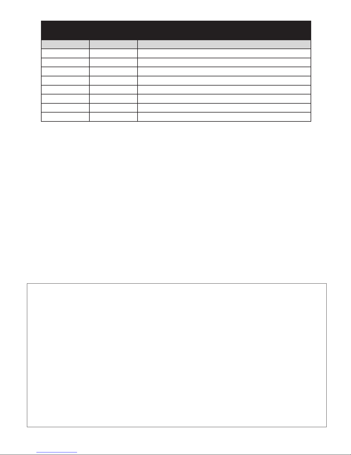
Fitting Kit
Option Part number Description
K50 & KP50 Fitting Kit fk1-059 (5) Cable clips
(3) No6 x
(3) Wall plugs 22mm
(1) 8mm x 3mm small self tapping screw - zinc
K75 & KP75 Fitting Kit fk1-061 (5) Cable clips
(3) No8 x 1 woodscrew - zinc
(3) Wall plugs 35mm
(1) 8mm x 3mm small self tapping screw - zinc
3
/4 woodscrew - zinc
Unit installation / test
Maintenance/
This unit is for Indoor use only
Standard Unit - Drill a hole in the surface for the rear data cable. Secure the unit to the surface with three screws
as per tting diagram on page 1. 3 suitable screws and xings are provided for tting the unit to a wall. Ensure
the data cable has free access at the rear.
A choice of black and white covers are also provided. Hook the required cover over the top of the reader, press
home at the bottom and secure with the single xing screw.
Screw Terminal Unit - The adapter (310-750-US) is mounted to a standard backbox using the xing screws
provided. The 75mm reader is then mounted onto the adapter using the tting kit provided with the reader.
KP series - When chosing a location for the reader, ensure that it is a least 12 inches from other readers. This will
include readers mounted on the other side of the same wall as the radio signal will cause interference and reduce
the read range. The reader should not be used on metal surfaces as the reected signal will also reduce the range.
Powering up the keypad will cause all the LEDs to come on. Once the control unit has been congured to accept
keypad input (see controller instructions) pressing any key will make the keypad sound a bleep. Check the
following FAQ section for assssistance if any problems are encountered.
Following the completed installation of this equipment, no further maintenance or testing is required.
It is advisable to ensure that any third party backup power supplies or recovery procedures are checked regularly
to ensure that the operation of the Paxton system is not compromised.
FCC Compliance
Class B digital devices.
This equipment has been tested and found to comply with the limits for a Class B digital device, pursuant to Part 15 of the
FCC Rules. These limits are designed to provide reasonable protection against harmful interference in a residential installation.
This equipment generates, uses and can radiate radio frequency energy and, if not installed and used in accordance with the
instructions, may cause harmful interference to radio communications. However, there is no guarantee that interference will
not occur in a particular installation. If this equipment does cause harmful interference to radio or television reception, which
can be determined by turning the equipment off and on, the user is encouraged to try to correct the interference by one or
more of the following measures:
-- Reorient or relocate the receiving antenna.
-- Increase the separation between the equipment and receiver.
-- Connect the equipment into an outlet on a circuit different from that to which the receiver is connected.
-- Consult the dealer or an experienced radio/TV technician for help.
Class A digital devices.
This equipment has been tested and found to comply with the limits for a Class A digital device, pursuant to part 15 of the
FCC Rules. These limits are designed to provide reasonable protection against harmful interference when the equipment is
operated in a commercial environment. This equipment generates, uses, and can radiate radio energy and, if not installed and
used in accordance with the instruction manual, may cause harmful interference to radio communications. Operation of this
equipment in a residential area is likely to cause harmful interference in which case the user will be required to correct the
interference at his own expense.
This device complies with Part 15 of the FCC Rules. Operation is subject to the following two conditions:
(1) this device may not cause harmful interference, and (2) this device must accept any interference received, including
interference that may cause undesired operation. Changes or modications not expressly approved by the party responsible
for compliance could void the user's authority to operate the equipment.
PAGE 3
Page 4

Here is the list of topics about this product that receive the most technical support inquiries.
We list them here to help you speed up the installation and trouble shooting process.
1 - Net2 - Bell function.
QPressing the bell button on the keypad will result in Relay 2 being energised for 1 second. A bell sounder can be
Qcontrolled by wiring one of the bell feeds across COM / NO on the relay.
2 - Readers/keypads not working.
Q- Software settings - Conrm that the settings of the reader or keypad are correct.
Q- Connections - Check the wiring of the connectors. Where possible, test this reader on the other port.
Q- Extended Cable - Belden 9538 should be used. Twisted pair alarm cable should not be used.
Q To conrm that an extended cable is not at fault, wire the reader direct into the reader port.
Q- Supply voltage - Conrm that the voltage is within specication. (see table)
Q- User token - Conrm that the user token used for testing is OK by presenting it to a known working reader.
Q- Interference - Conrm whether the reader works when tested 'in hand' and not mounted on the wall. Ensure
Q that readers are not mounted back to back or there is no interference from other local RF devices.
3 - Duress Codes.
QNet2 - Duress codes cannot be programmed into Net2.
QSwitch2 - These systems can accept Duress codes.
Specications
Environment
Operating temperatures - all items
Waterproof - Fixed cable
Min
-35 °C (-31 °F)
IPX7
Waterproof - K75 - Screw connection
Cable length
Electrical
Voltage
Min
9V DC 13V DC
Current
Clock and data bit period
Backlight
Dimensions
Width
Not with Stainless Steel keypad
K50 2 inch 4 inch
K75 3 inch 5
Max
+66 °C (+151 °F)
Max
120 mA
Height
1
/
2 inch
KP Specic
Electrical
Min
Voltage
Current
Clock and data bit period
Carrier frequency
Dimensions
Width
KP50 2 inch 4 inch
KP75 3 inch 5
Read Range
Token
KP50 3 inch 2 inch
KP75 4 inch 2
Max
180 mA
Height
1
/
2 inch
Keyfob
1
/
2 inch
Outdoor use
Indoor use
10 feet
600 µs
Depth
5
/
8 inch
5
/
8 inch
12V DC
600 µs
125 kHz
Depth
5
/
8 inch
5
/
8 inch
Hands Free Token
4 feet
5 feet
PAGE 4
 Loading...