

Page 1
® ®
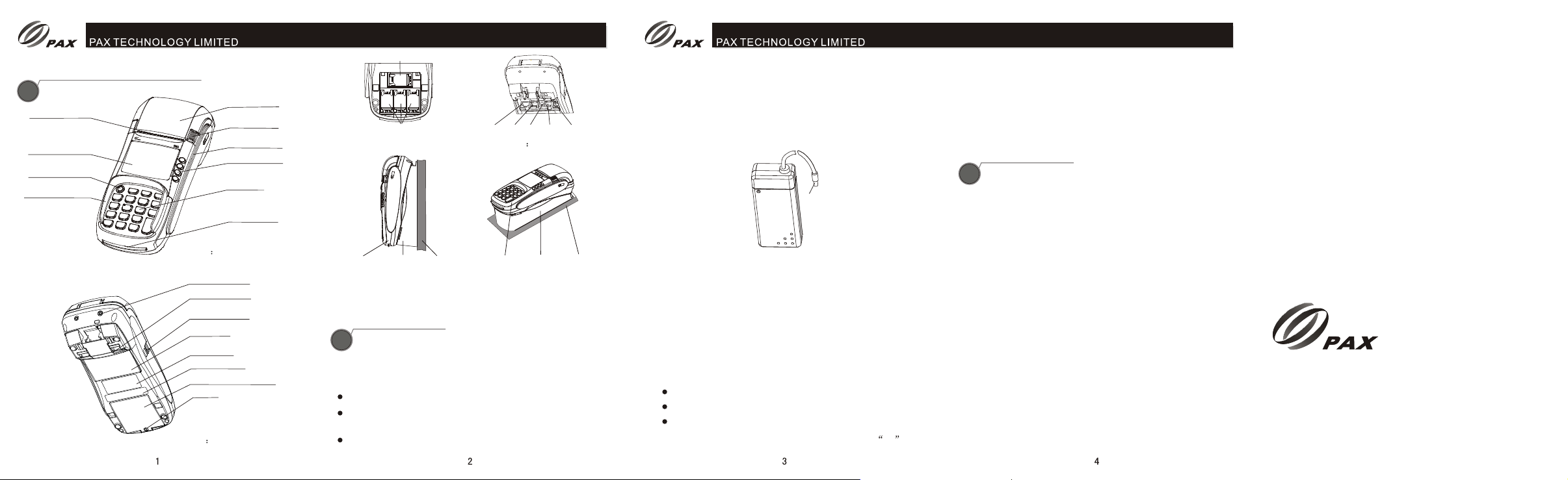
Product Description
Product Description
1
Paper cutter
LCD display
On/off Key
Privacy shield(Opt.)
Paper cover
Paper cover
release key
Magnetic strip
card slot
ATM-style key
Keypad
IC Card slot
Figure 1 Top View
Contactless Card Reader
Interface
Hang hole(Opt.)
USB port
Port cover
Nameplate
Bar code lable
SAM/SIM socket cover
Screw
Figure 2 Bottom View
SIM
SAM
Figure 3: SAM/SIM Socket
Wall Mounting Device
POS
Figure 5: S80 Wall Mounting Device
Note: The above figure shows S80 equipped Wall Mounting Device
which is optional.
Installation
Installation
LAN /RS232B
LINE
Power
Figure 4 Ports at Bottom
POS
Wall
Wall Mounting Device
RS232A
PINPAD
Wall
2
1) Place S80 on table
2) Connect the attached cable
Remove port cover on bottom of S80
Connect each plug of the attached cables into the
corresponding sockets on the rear panel of the terminal.
Put the port cover back.
3) Insert the telephone cord supplied with the terminal into
standard RJ-11 type outlet. Connect the other end of the
telephone cord into a standard RJ-11 type modular
telephone line outlet.
The figure below shows cable installation.
Power
4) Connect serial facility to RS232 socket.
5) Connect AC plug of power adaptor into AC socket.
6) Place paper roll into S80
Press the paper cover release key to open paper cover.
Insert paper roll along the arrow.
Lead the paper out and place the paper on paper cut and
push the paper cover downward until a sound of ka can
be heard.
7) Turn on S80, LCD backlight is on. On screen initialization
and application interface show on one after another.
8) To perform a simulation of transaction successfully thus
S80 installation is OK.
Instruction
Instruction
3
1) Power on/off
Power on: Press the red button for about 2 seconds until
LED backlight on, the POS is on.
Power off: Press the red button for about 2 seconds until the
content of display vanishes, the POS is off.
2) Magnetic swipe
When pulling a magnetic card along the slot, make the
magnetic stripe face the machine. Bi-directional pulling the
magnetic card is acceptable. It is recommended from up to
down, and with a steady speed.
3) IC card operational description
When insert a card, make the contact of the card upward.
Gently insert and withdraw the card In order to protect the
contact on card and IC card connector.
4) Tear paper operation
Hold the end of paper along with the paper cut as an angle
of 45 degree and swiftly and evenly tear the paper off.
PAX TECHNOLOGY LIMITED reserves
the right to change product technology
specifications without notifying.
®
PAX TECHNOLOGY LIMITED
Room 2416, 24/F., Sun Hung Kai Centre, 30
Harbour Road, Wanchai, Hong Kong
Tel: +852-2588 8808 Fax: +852-2802 3300
E-mail: daniel@pax.com.hk
Website: www.pax.com.hk
Page 2
® ®
Notice at Installation and Use
Notice at Installation and Use
4
1) Use a power bar well grounded and with a fuse in it.
2) Protect power supply cable and power adaptor. If they are
broken, they are no longer be used.
3) Before connect power bar to AC socket, make sure the
voltage is correct as POS states.
4) POS should be placed steady on table. It is not allowed
make it under sun beam, high temperature, high humidity or
place full of dust.
5) Keep it away from liquid.
6) Don't insert hard stuff into port which may damage POS
severely.
7) When a POS is in failure, please contact designated
personnel to maintain it. It is not allowed to repair it on your
own.
8) When insert paper roll, do not touch paper cut and protect
your finger from being hurt.
9) Only use designated paper roll to avoid paper jam or
damaging the printer.
Specification
Specification
5
Default
CPU: 32-bit ,ARM9
Memory: 8MB Flash, 16MB SDRAM
Display: 128 x 64 pixel LCD, LED backlight
Keypad: 10 alphanumeric keys, 8 functional keys,
4 ATM keys, 1 switch(on) key
Magnetic Card Reader:
ISO7812, Track 1/2/3,
bi-directional swipe
IC Card Reader: 1, EMV2000 compliant
SAM Slots: 3, ISO7816
Modem: Sync. (
V.21,V.22/V.22bis,V.29
Async. (V.92, )
Peripheral Ports: 1 RS232, 1 PIN Pad, 1 line port,
1 Phone port
Printer: Thermal printer, Speed: 20 lines/sec,
Paper width: 57mm
Paper roll outer diameter: 50mm
Power Supply: Input 100-240VAC, 50Hz/60Hz, 1.5A
Output 8.2VDC, 5A
Working Environment: Temperature:0 40 (
R.H. :10% 90%(non-condense)
Storage Environment: Temperature:-20 70 (
R.H. :5% 95% non-condense
Dimensions: 216mm x 95mm x 86mm (L x W x H,
Weight 525g
Optional:
Built-in Ethernet module
HDLC up to 9600bps,
)
up to 56Kbps
, 1 USB port
32 104 )
-4 150 )
including the keypad privacy shield)
Built-in GPRS module
Contactless Card Reader (Can connect with an external
contactless card reader as an integrated
design of POS system. ISO/IEC14443
Type A/B, 4 LEDs RF Indicator)
Mass storage: 128MB
PIN Protection
PIN Protection
The following techniques can be employed to provide for
effective screening of the PIN-entry during the PIN entry
process. These methods would typically be used in combination,
though in some cases a method might be used singly.
Positioning of terminal on the check-stand in such way as to
make visual observation of the PIN-entry process infeasible.
Examples include:
Installing PED on an adjustable stand that allows consumers to
-Visual shields designed into the check-stand. The shields
may be solely for shielding purposes, or may be part of
the general check-stand design, e.g., used as selling
area.
-Position the PED so that it is angled in such a way to
make PIN spying difficult.
swivel the terminal sideways and/or tilt it forwards/backwards to
a position that makes visual observation of the PIN-entry
process difficult.
Positioning of in-store security cameras such that the PIN-entry
keypad is not visible.
Post instructions around check-stand, in order to inform
customers. Instructing the cardholder regarding safe PIN-entry.
When the cardholder input his/her PIN, he/she had better use
his/her body and hands to prevent visual observation of PIN-
entry process.
Note To protect the process of PIN-entry, it is not limited to the
above methods and examples, merchants also can adopt other
methods and steps to keep cardholder's PIN safe.
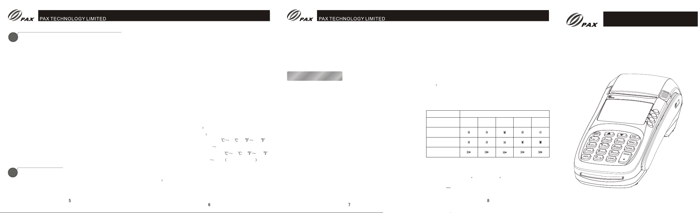
S80 PIN-entry observation corridors v.s. PIN protection methods
Observation Corridors
Method
S80 in Check-Stand
with shield
S80 on
Adjustable Stand
Post Customer
Instruction
Note *Customer instruction methods are less repeatable and
therefore should be used in combination with other methods.
Security levels: L = low M = medium H = high
CAUTION To reduce the risk of fire, use only No.26 AWG
or larger telecommunication line cord
Cashier
Customers
in Queue
Customers
Elsewhere
On-Site
Camera
Remote
Cameras
®
Installation Manual
S80
Handover
Countertop Payment Terminal
S80S80
PAX TECHNOLOGY LIMITED
Page 3

Note: RSS232 Port only used as upgraded EUT by manufacturer
Warning:
We declare that:
※ The FCC ID label is placed on Payment Terminal clearly visible to all persons at the
time of purchase.
※ The user is cautioned that changes or modifications not expressly approved by the
manufacturer could void the user’s authority to operate the equipment.
※ This device complies with part 15 of the FCC Rules. Operation is subject to the
following two conditions:
(1) This device may not cause harmful interference, and
(2) This device must accept any interference received, including interference that may
cause undesired operation.
※ Do not attempt to disassemble the Payment Terminal by yourself.Non-expert
handling of the devices may damage them.
※ Your Payment Terminal is a radio transmitter and receiver. It is designed and
manufactured not to exceed limits for exposure to radio frequency (RF) energy set by the
Federal Communications
※ Commission (FCC) of the U.S. Government. These limits are part of comprehensive
guidelines and establish permitted levels of RF energy for the general population. The
guidelines are based on standards that were developed by independent scientific
organizations through periodic and thorough evaluation of scientific studies. The
standards include a substantial safety margin designed to assure the safety of all persons,
regardless of age or health. The exposure standard for Payment Terminal employs a
unit of measurement known as the Specific Absorption Rate, or SAR. The SAR limits set
by the FCC are 1.6 W/Kg. Tests for SAR are conducted using standard operating positions
accepted by the FCC with the Payment Terminal transmitting as its highest certified
power level in all tested frequency bands. Although the SAR is determined at the highest
certified power level, the actual SAR level of the phone while operating can be well below
the maximum value. This is because the Payment Termina is designed to operate at
multiple power levels so as to use only the power required to reach the network. In
general, the closer you are to a wireless base station, the lower the output power.
This equipment complies with FCC radiation exposure limits set forth for an uncontrolled
environment .
Note: This equipment has been tested and found to comply with the limits for a Class B digital
device, pursuant to part 15 of the FCC Rules. These limits are designed to provide reasonable
protection against harmful interference in a residential installation. This equipment generates,
uses and can radiate radio frequency energy and, if not installed and used in accordance with
the instructions, may cause harmful interference to radio communications. However, there is no
guarantee that interference will not occur in a particular installation. If this equipment does cause
harmful interference to radio or television reception, which can be determined by turning the
equipment off and on, the user is encouraged to try to correct the interference by one or more
of the following measures:
—Reorient or relocate the receiving antenna.
—Increase the separation between the equipment and receiver.
—Connect the equipment into an outlet on a circuit different from that to which the
receiver is connected.
—Consult the dealer or an experienced radio/TV technician for help.
 Loading...