

Page 1
PAX TECHN OLOGY I NC.
PAX TECHN OLOGY I NC.
PAX TECHN OLOGY I NC.
x
P terminals that include a default communication module come
standard with one Ethernet port and RS232, USB, and PUSB
network capabilities. However, if the default communication
module is replaced with an optional communication module,
your choice of these additional network capabilities are
available:
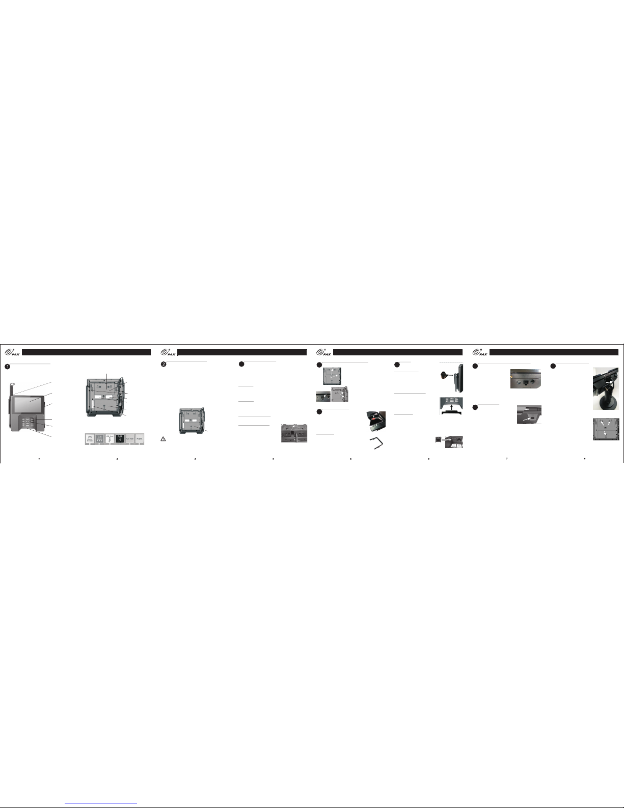
Commu nicat ion Mod ule
Commu nicat ion Mod ule
Power C onnec tions
Power C onnec tions
3
Pro duct De scrip tion
Pro duct De scrip tion
• A second Et herne t port
• Power o ver Eth ernet
• An Ether net hub
• Wi-Fi a nd Blue tooth L E
• Wi-Fi a nd Cell ular GS M
The commu nic ation mo dule i s locat ed on the u nders ide of
the ter minal .
Commu nicat ion
modul e
Power down and remove all power from the terminal before
removing or installing a communication module. A
communication module must be installed before power can be
applied to the terminal.
WARNIN G:
Working Environment: Temperature -10°C~50°C (14°F~122°F)
R.H.: 10%~93% (non-condensing)
Storage Environment: Temperature -20°C~60°C (-4°F~140°F)
R.H.: 5%~95% (non-condensing)
Stylu s pen
Touch scr een
and
Conta ctles s
reade r area
Magne tic
strip e reade r
Priva cy shie ld
Keypa d
Smart c ard
reade r
Cable r etent ion
cover p late
Commu nicat ion
ports - l ocate d
under c over pl ate
Speak ers
MAC add ress la bel
Regul atory l abel
Commu nicat ion
modul e
Commu nicat ion por ts are la beled a nd colo r-cod ed:
White R ed Yellow B lack Green Blue
Part nu mber/
seria l numbe r label
Power can be supplied via the power port or a single data cable
that carries power. This power can be provided via a “powered
cable” where the connected POS terminal provides the power
x
(i.e. PUSB or Power over Ethernet) or by connecting a P power
supply directly to the data cable (i.e. RS232 or USB).
1) Power Port
Insert the power connector into the green POWER port. Turn
the power connector, locking the tab behind the short plastic
wall. Dress the cable through the retention clips. A separate
data cable is also required.
2) POS Cable
Insert the cable connector into the appropriate port on the
terminal. Dress the cable through the retention clips opposite
the port. Connect power supply to cable as required. The cash
register could also supply power to terminal.
3) Power over Ethernet (PoE)
Power is available over the red LAN1 port when the optional
PoE communication module is installed.
Cable Retention Cover Plate
After power and data cables are
connected and dressed through
retention clips, install the cable
retention cover plate and secure
with captive screw.
Screw
Sty lus Hol der and P en
Sty lus Hol der and P en
4
1)
Mountin g
Locatio ns
2)Styl us Port
3)
Retenti on
Clips
1) Align stylus holder over
metal screw openings at left
side or top of terminal. Insert
tabs into indentations along
edge. Attach with captive
screws.
2) Insert connector end of
stylus pen into stylus port on
left side of terminal.
3) Use enclosed plastic card to
press stylus cord into retention
clips on left side of terminal.
Priv acy Shi eld
Priv acy Shi eld
5
Insert tabs and snap shield firmly in place
to left and right of keypad. Not designed to
be removable. Removing the shield breaks
the retention tabs and the ability to remotely
track the status of the shield is lost.
1Priv acy Shi eld
Decor ative P lug
Decorative Plug – If a privacy shield is not
installed, a non-removable decorative plug
may be installed in its place. This plug does
not provide any PIN entry privacy.
CAUTION: If the privacy shield is not installed,
you must use PCI-approved alternative methods
to secure the PIN pad.
Plug s
Plug s
6
1) Stylus Holder Plug
If required, to prevent stylus pen from
being inserted vertically into stylus
holder, firmly insert plug into opening
in holder, aligning with curve of stylus
holder.
2) Smart Card Reader Plug
If required, insert smart card reader
plug into smart card receptacle slot.
To remove, if required, gently pry out
the plug using a small screwdriver in
the slit along top of plug.
3) Ethernet Plug
An Ethernet plug is included in case
you want to block an inactive LAN port.
Align plug so that it matches the shape
of the port and gently push into opening.
To remove, if required, gently pry off
using a small screwdriver in the slit
along the top of the plug.
Note: LAN2 port is enabled only when
Ethernet hub or PoE and Ethernet hub
communication module is installed.
1) Stylus
Holder
Plug
2) Smart Card Reader Plug
3) Etherne t
Plug
Mounti ng
Slots
Stan d Instal latio n
9
Stan d Instal latio n
PAX TECHN OLOGY I NC.
Route
Cables
x
If required, the P terminal may be
mounted to a stand.
Instructions may vary depending
on stand specifications.
Carefully route the required cables
up through the stand pipe and out
the top. Connect the cables to the
x
P terminal ports.
Insert the three mounting slots on
the underside of the terminal into
the three metal prongs on the stand
base.
Slide the terminal firmly into position,
locking the terminal in place on the
stand. Secure with fastening screw
or locking device as required.
Rese t Button a nd Audi o Jack
7
Rese t Button a nd Audi o Jack
Reset
Button
Audio Ja ck
If required, restart the
terminal by pressing in
and holding the reset
button for 2-3 seconds
If required, a visually disabled person can connect a
headphone to the terminal for audio prompting using the
3.5mm output audio jack.
Cabl e Lock
8
Cabl e Lock
If required, insert customer-provided
cable lock into K-Slot®. Loop cable
around permanent object to secure
in place.
Stylus P ort
Page 2

PAX TECH NOLOG Y INC.
Avail able Ac cesso ries
Clea ning th e Devic e
10
Clea ning th e Devic e
WARNING:
Do not use industrial strength or abrasive cleaner as it may
damage or scratch the screen.
Do not immerse device in water (or liquid.)
Do not spray water or cleaner into the MSR slot, Smart Card
Reader or ports.
To clean screen, apply distilled water or mild glass cleaner
onto a soft, lint-free cloth and gently wipe terminal screen.
To clean terminal, apply distilled water or plastic-safe cleaner
onto a soft, lint-free cloth and gently wipe terminal.
11
Avail able Ac cesso ries
RS232 Cable
200204020000140
Requires Power Supply
USB Cable
200204020000141
Requires Power Supply
Power Supply
200310110000070
Requires Power Cord
Power Cord
200311020000023
Requires Power Supply
Stylus Pen
200209090000929
Stylus Holder Plug
200209090000930
Decorative Privacy
Shield Plug
2002090900001037
Privacy Shield
200209060000040
PAX TECHN OLOGY I NC.
9
10
This doc ument i s provi ded to yo u for inf ormat ional p urpos es
only. All f eature s and spe cific ation s are subj ect to ch ange
withou t notic e. PAX's na me and PAX's l ogo are re giste red
tradema rks of PAX Tec hnolo gy Inc. A ll righ ts reser ved.
PAX Technol ogy Inc .
4901 Be lfort R oad, Su ite 130
Jacks onvil le, FL 322 56, USA
T: 877-8 59-00 99
W: www.pa x.us
E: sale s@pax .us
P/N:2 00312 00000 0224
FCC Regulations:
This device complies with part 15 of the FCC Rules.
Operation is subject to the following two conditions: (1) This
device may not cause harmful interference, and (2) this
device must accept any interference received, including
interference that may cause undesired operation.
This device has been tested and found to comply with the
limits for a Class B digital device, pursuant to Part 15 of the
FCC Rules. These limits are designed to provide
reasonable protection against harmful interference in a
residential installation. This equipment generates, uses and
can radiated radio frequency energy and, if not installed and
used in accordance with the instructions, may cause
harmful interference to radio communications. However,
there is no guarantee that interference will not occur in a
particular installation If this equipment does cause harmful
interference to radio or television reception, which can be
determined by turning the equipment off and on, the user is
encouraged to try to correct the interference by one or more
of the following measures:
-Reorient or relocate the receiving antenna.
-Incr ease th e separ ation b etwee n the equ ipmen t and
recei ver.
-Conn ect the e quipm ent int o an outl et on a cir cuit
differ ent fro m that to w hich th e recei ver is co nnect ed.
-Cons ult the d ealer o r an expe rienc ed radi o/TV
techn ician f or help .
Cauti on: Cha nges or m odifi catio ns not ex press ly
appro ved by th e party r espon sible f or comp lianc e could
void th e user' s autho rity to o perat e the equ ipmen t.
RF Exp osure I nform ation
This de vice me ets the g overn ment' s requi remen ts for
expos ure to ra dio wav es.Th is devi ce is des igned a nd
manuf actur ed not to e xceed t he emis sion li mits fo r
expos ure to ra dio fre quenc y (RF) en ergy se t by the
Feder al Comm unica tions C ommis sion of t he U.S.
Gover nment .
This de vice co mplie s with FC C radia tion ex posur e limit s
set for th for an u ncont rolle d envir onmen t. In ord er to
avoid t he poss ibili ty of exc eedin g the FCC r adio
frequ ency ex posur e limit s, huma n proxi mity to t he
anten na shal l not be le ss than 2 0cm (8 in ches) d uring
norma l opera tion.
11 12
5
 Loading...