

PAW RHT Series, RHK DN 25, RHK Series, RHT DN 20, RHT DN 25 Installation And Operation Instructions Manual

PAW GmbH & Co. KG
Montage- und Bedienungsanleitung
Pumpensets zur Rücklaufhochhaltung
Installation and Operation Instructions
Pump Sets for Return Flow Temperature Maintenance
Notice de montage et d'utilisation
Sets de circulateur pour le maintien
de la température retour
Manual de instrucciones
Kits de bomba para mantenimiento
de la temperatura retorno
Istruzioni per il montaggio e per l'uso
Set di pompe per l'innalzamento
della temperatura di ritorno
Böcklerstr. 11, D-31789 Hameln, Germany
Tel.: +49-5151-9856-0, Fax: +49-5151-9856-98
E-mail: info@paw.eu, Web: www.paw.eu
2018/02 999612x-mub-ml – V08
RHT RHK

1
Allgemeines
Art. Nr. / Item no. / N° d'article / Nº de art. / Cod. art. 999612x-mub-ml
Version / Versión / Versione V08
Technische Änderungen vorbehalten!
PAW GmbH & Co. KG
Böcklerstraße 11
We reserve the right to make technical changes without notice!
Sous réserve de modifications techniques !
¡Sujeto a modificaciones técnicas!
Con riserva di modifiche tecniche!
D-31789 Hameln, Germany
www.paw.eu
Tel: +49 (0) 5151 9856 - 0
Printed in Germany – Copyright by PAW GmbH & Co. KG
A-2 999612x-mub-ml – V08 2018/02
Fax: +49 (0) 5151 9856 - 98

1
Inhaltsverzeichnis
1
Allgemeines ............................................................................................................
A-4
2
Sicherheitshinweise .................................................................................................
A-5
3
Produktbeschreibung ...............................................................................................
A-6
4
Montage und Installation [Fachmann] .......................................................................
A-9
5
Technische Daten ...................................................................................................
A-11
Allgemeines
A Deutsch
1.1 Geltungsbereich der Anleitung............................................................................. A-4
1.2 Bestimmungsgemäße Verwendung
..................................................................... A-4
3.1 Ausstattung ......................................................................................................... A-6
3.2 Funktion
3.3 Thermisches Regelventil
.............................................................................................................. A-6
..................................................................................... A-8
4.1 Zubehör: Schneidringverschraubung (nicht im Lieferumfang enthalten) .............. A-9
4.2 Montage
.............................................................................................................. A-10
5.1 Druckverlust- und Pumpenkennlinien .................................................................. A-12
2018/02 999612x-mub-ml – V08 A-3

1
1 Allgemeines
1.1 Geltungsbereich der Anleitung
1.2 Bestimmungsgemäße Verwendung
nicht
Allgemeines
Diese Anleitung beschreibt die Funktion, Installation, Inbetriebnahme und Bedienung der
Pumpensets RHT DN 20 und DN 25 und RHK DN 25 für die Rücklaufhochhaltung. Für andere
Komponenten der Anlage, wie z. B. die Pumpe oder den Regler, beachten Sie bitte die
Anleitungen des jeweiligen Herstellers. Die mit [Fachmann] bezeichneten Kapitel richten sich
ausschließlich an den Fachhandwerker.
Das Pumpenset darf nur in Heizungskreisen unter Berücksichtigung der in dieser Anleitung
angegebenen technischen Grenzwerte verwendet werden. Das Pumpenset darf
in
Trinkwasseranwendungen eingesetzt werden. Die bestimmungswidrige Verwendung des
Pumpensets führt zum Ausschluss jeglicher Haftungsansprüche.
Verwenden Sie ausschließlich PAW-Zubehör in Verbindung mit dem Pumpenset.
Die Verpackungsmaterialien bestehen aus recycelbaren Materialien und können dem normalen
Wertstoffkreislauf wieder zugeführt werden.
A-4 999612x-mub-ml – V08 2018/02

2
2 Sicherheitshinweise
VORSICHT
Personen- und Sachschaden!
nicht
ACHTUNG
Sachschaden durch Mineralöle!
Sicherheitshinweise
Die Installation und Inbetriebnahme sowie der Anschluss der elektrischen Komponenten setzen
Fachkenntnisse voraus, die einem anerkannten Berufsabschluss als Anlagenmechaniker/in für
Sanitär-, Heizungs- und Klimatechnik bzw. einem Beruf mit vergleichbarem Kenntnisstand ent-
sprechen [Fachmann]. Bei der Installation und Inbetriebnahme muss folgendes beachtet werden:
• Einschlägige regionale und überregionale Vorschriften
• Unfallverhütungsvorschriften der Berufsgenossenschaft
• Anweisungen und Sicherheitshinweise dieser Anleitung
Das Pumpenset ist nur geeignet für den Einsatz in Heizungskreisen mit
Heizungswasser gemäß VDI 2035 / Ö-Norm H 5195-1.
Das Pumpenset darf
Mineralölprodukte beschädigen die EPDM-Dichtungselemente nachhaltig, wodurch die Dicht-
eigenschaften verloren gehen. Für Schäden, die durch derartig beschädigte Dichtungen
entstehen, übernehmen wir weder eine Haftung noch leisten wir Garantieersatz.
Vermeiden Sie unbedingt, dass EPDM mit mineralölhaltigen Substanzen in Kontakt
kommt.
Verwenden Sie ein mineralölfreies Schmiermittel auf Silikon- oder Polyalkylenbasis, wie
z. B. Unisilikon L250L und Syntheso Glep 1 der Firma Klüber oder Silikonspray.
in Trinkwasseranwendungen eingesetzt werden.
2018/02 999612x-mub-ml – V08 A-5

3
3 Produktbeschreibung
3.1 Ausstattung
Produktbeschreibung
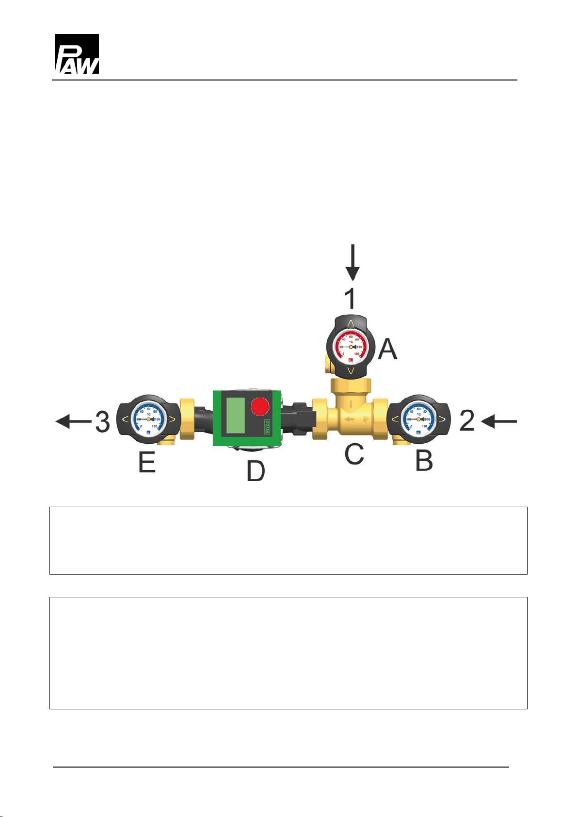
Die Pumpensets RHT und RHK sind vormontierte Armaturengruppe für Heizungskreise.
Die Pumpe kann durch die Kugelhähne abgesperrt werden und kann so einfach gewartet werden,
ohne dass das Wasser im Heizungskreis abgelassen werden muss.
1 Bypass (zum Kesselvorlauf)
2 Pufferspeicherrücklauf
3 Kesselrücklauf
A Kugelhahn Vorlauf
B Kugelhahn Rücklauf
C Thermisches Regelventil mit automatischem Bypass
D Heizungspumpe
E Kugelhahn Rücklauf
A-6 999612x-mub-ml – V08 2018/02

3
3.2 Funktion
Pumpensets RHT / RHK zur Rücklaufhochhaltung
Einsatzgebiete:
ACHTUNG
Funktionsstörung
Produktbeschreibung
Mit Hilfe des Pumpensets wird eine Unterschreitung des Taupunktes im Kessel und damit die
Kesselversottung verhindert.
Das Pumpenset wird zwischen den Pufferspeicher und den Kessel montiert. Das thermische
Regelventil öffnet den Rücklauf zum Speicher erst, wenn der Kesselkreis die Öffnungstemperatur
von 50 °C bzw. 60 °C erreicht hat. Dann steht die Leistung der Pumpe zur Beladung des
Speichers zur Verfügung.
• für Wärmequellen, bei denen eine Rücklaufhochhaltung notwendig ist,
wie z.B. Festbrennstoffkessel, Holzfeuerungslagen und Kamine
Wenn die Kesselleistung über die Kesseltemperatur gesteuert wird, sollte der Kessel um
20 °C über die Öffnungstemperatur der Rücklaufhochhaltung aufheizen. Andernfalls
regelt der Kessel die Leistung herunter, noch bevor das thermische Ventil vollständig
öffnet.
2018/02 999612x-mub-ml – V08 A-7
3
3.3 Thermisches Regelventil
Temperaturen:
t
= t
t
= t
tKR > tPR
Produktbeschreibung
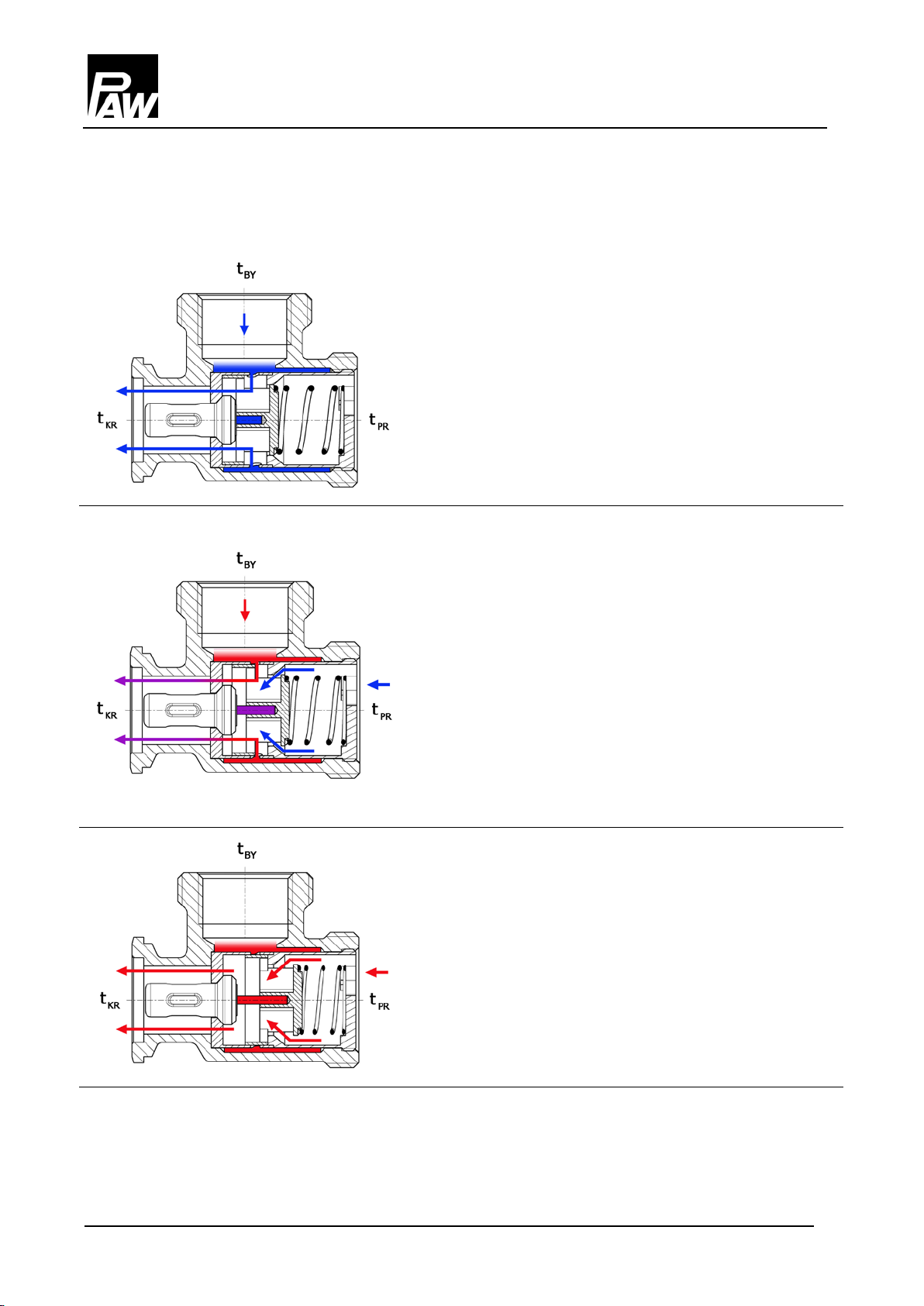
Das thermische Regelventil ermöglicht in der Anlaufphase einen automatischen Bypassbetrieb.
t
< t
KR
tKR = t
< t
t
KR
FIX
FIX
BY
1. Solange die Wassertemperatur im Kesselkreis
unterhalb der Öffnungstemperatur des Regeventils
ist, verschließt es den Weg zum Pufferspeicher.
Die Pumpe wälzt das Wasser im Kesselkreis über
den Bypass um, das geringe Wasservolumen des
Kesselkreises kann sich nun schnell erwärmen.
2. Erreicht der Kesselkreis die Öffnungstemperatur
des Regelventils, verschließt es den Bypass und
öffnet den Weg zum Pufferspeicherkreis. Das kalte
Wasser aus dem Pufferspeicher-Rücklauf
vermischt sich im Regelventil mit dem heißen
Kesselkreis-Wasser. So wird die
Rücklauftemperatur im Kesselkreis auf das
gewünschte Niveau angehoben und verhindert eine
Kondensatbildung im Kessel.
tKR ≥ t
FIX
3. Übersteigt die Pufferspeicher-Rücklauftemperatur
die Öffnungstemperatur, schließt das Regelventil
den Bypass vollständig. Das Wasser aus dem
Pufferspeicherkreis gelangt nun direkt in den
Kesselkreis.
tBY = Bypass tKR = Kesselrücklauf
= Pufferspeicher-Rücklauf t
t
PR
= Öffnungstemperatur
FIX
A-8 999612x-mub-ml – V08 2018/02

4
4 Montage und Installation [Fachmann]
ACHTUNG
Sachschaden
ACHTUNG
Sachschaden
4.1 Zubehör: Schneidringverschraubung (nicht im Lieferumfang enthalten)
Montage und Installation [Fachmann]
Um Schäden an der Anlage zu verhindern, muss der Montageort trocken, tragsicher, frostfrei
und vor UV-Strahlung geschützt sein.
Montieren Sie die Pumpe immer im Rücklauf zum Kessel, da sie durch die hohen
Vorlauftemperaturen beschädigt werden könnte.
Die Anbindung an die Heizungsinstallation kann schnell, druckdicht und lötfrei durch optional
erhältliche Schneidringverschraubungen erfolgen.
1. Schieben Sie die Überwurfmutter ② und den Schneid-
ring ③ auf das Kupferrohr ①. Damit eine sichere
Krafteinleitung und Abdichtung gewährleistet ist, muss
das Rohr mindestens 3 mm aus dem Schneidring heraus stehen.
2. Schieben Sie die Stützhülse ④ in das Kupferrohr.
3. Stecken Sie das Kupferrohr mit den aufgesteckten
Einzelteilen (②, ③ und ④) so weit wie möglich in das
Gehäuse der Schneidringverschraubung ⑤ hinein.
4. Schrauben Sie die Überwurfmutter ② zunächst hand-
fest an.
Nicht im Lieferumfang enthalten!
2018/02 999612x-mub-ml – V08 A-9
5. Ziehen Sie die Überwurfmutter ② mit einer ganzen
Umdrehung fest an. Um den Dichtring nicht zu beschädigen, sichern Sie hierbei das Gehäuse der
Schneidringverschraubung ⑤ gegen Verdrehen.
4
4.2 Montage
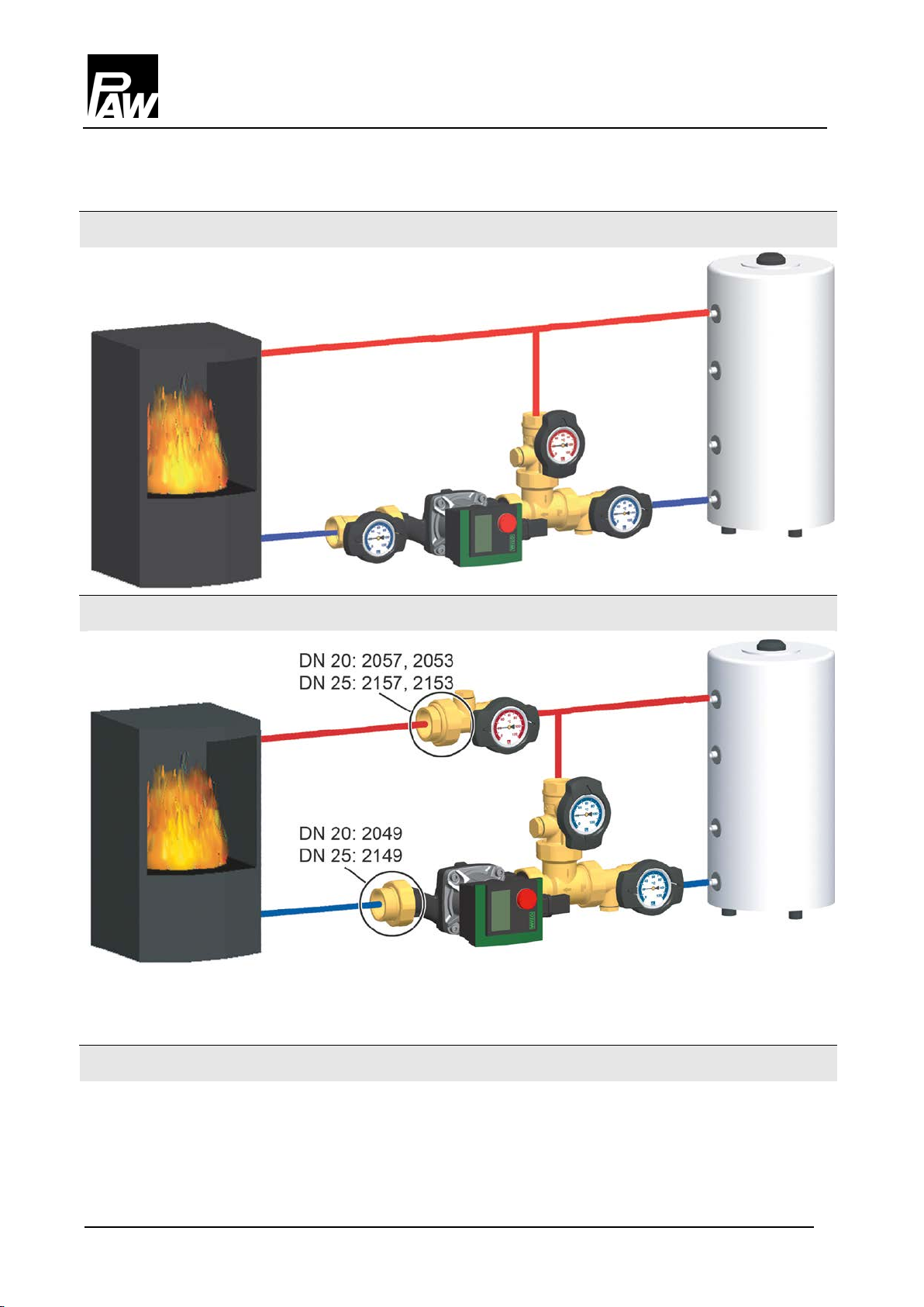
Montagevariante A
Montagevariante B
Optionales Zubehör zur Montage in den ½"-Muffen der Kugelhähne
Montage und Installation [Fachmann]
Montagevariante B ermöglicht das komfortable Absperren des Wärmeerzeugers ohne zusätzliche
Absperrhähne. Zusätzlich erforderlich: Dichtung, Einschraubteil, Pumpen-Verschraubung
Art. Nr. 566001 Tauchhülse (als Temperaturmessstelle)
Art. Nr. 2260 KFE-Hahn mit Kontermutter zur Entleerung des Kesselkreises
A-10 999612x-mub-ml – V08 2018/02

5
5 Technische Daten
Pumpensets
RHT - DN 20
RHT - DN 25
RHK - DN 25
Abmessungen
Hydraulik
Werkstoffe
Technische Daten
Gesamthöhe
Gesamtbreite
112 mm 128 mm 140 mm
337 mm 428 mm 452 mm
Anschlüsse ¾" Innengewinde 1" Innengewinde 1" Innengewinde
Max. Druck 6 bar 6 bar 6 bar
Max. Temperatur 110 °C 110 °C 110 °C
Kvs-Wert [m3/h] 3,2 7,4 5,7
Einsatzbereich 6 m-Pumpe 30 kW (1300 l/h) 53 kW (2285 l/h) 47,5 kW (2045 l/h)
Öffnungstemperatur je nach Ausführung: 50 °C / 60 °C, Δt = 20 K
Armaturen Messing
Dichtungen EPDM / NBR
2018/02 999612x-mub-ml – V08 A-11

5
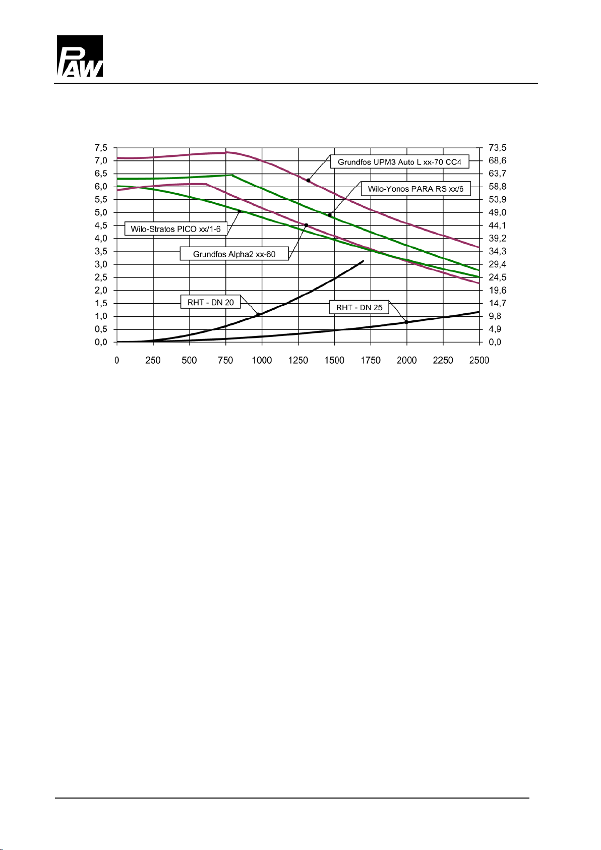
5.1 Druckverlust- und Pumpenkennlinien
Technische Daten
Druck [mWS]
Volumenstrom [l/h]
Lieferumfang siehe letzte Seiten dieser Anleitung.
Druck [kPa]
A-12 999612x-mub-ml – V08 2018/02

1
Contents
1
General information .................................................................................................
B-4
2
Safety instructions ...................................................................................................
B-5
3
Product description ..................................................................................................
B-6
4
Assembly and installation [specialist] ........................................................................
B-9
5
Technical data .........................................................................................................
B-11
General information
nglish
1.1 Scope of these instructions .................................................................................. B-4
1.2 Designated use
................................................................................................... B-4
3.1 Equipment ........................................................................................................... B-6
3.2 Function
3.3 Thermal control valve
.............................................................................................................. B-7
.......................................................................................... B-8
4.1 Accessories: compression fitting (not included in delivery) .................................. B-9
4.2 Assembly
............................................................................................................. B-10
5.1 Pressure drop and pump characteristics ............................................................. B-12
2018/02 999612x-mub-ml – V08 B-3

1
1 General information
1.1 Scope of these instructions
1.2 Designated use
not
General information
These instructions describe the installation, commissioning, function and operation of the RHT
DN 20 and DN 25 and RHK DN 25 pump sets for return flow temperature maintenance. For other
components of the heating system such as pumps or controllers, please observe the instructions of
the corresponding manufacturer. The chapters called [specialist] are intended for specialists only.
The pump sets may only be used in hydronic heating closed-loop systems taking into consideration
the technical limit values indicated in these instructions. The pump set must
be used in
domestic water applications. Improper usage excludes any liability claims.
Only use PAW accessories with the pump set.
The wrapping materials are made of recyclable materials and can be disposed of with recyclable
materials.
B-4 999612x-mub-ml – V08 2018/02

2
2 Safety instructions
CAUTION
Personal injury and damage to property!
not
NOTICE
Material damage due to mineral oils!
Safety instructions
The installation and commissioning as well as the connection of electrical components require
technical knowledge commensurate with a recognised vocational qualification as a fitter for
plumbing, heating and air conditioning technology, or a profession requiring a comparable level of
knowledge [specialist]. The following must be observed during installation and commissioning:
• Relevant local and national regulations
• Accident prevention regulations of the professional association
• Instructions and safety instructions mentioned in this manual
The pump set must only be used in hydronic heating closed-loop systems filled
with heating water according to VDI 2035 / Ö-Norm H 5195-1.
The pump set must
Mineral oil products cause lasting damage to seals made of EPDM, whereby the sealant
properties are lost. We do not assume liability nor provide warranty for damage to property
resulting from sealants damaged in this way.
It is imperative to avoid that EPDM gets in contact with substances containing mineral
oils.
Use a lubricant based on silicone or polyalkylene and free of mineral oils such as
Unisilikon L250L and Syntheso Glep 1 of the Klüber company or a silicone spray.
be used in domestic water applications.
2018/02 999612x-mub-ml – V08 B-5
3
3 Product description
3.1 Equipment
Product description
The RHT and RHK pump sets are preassembled fitting groups for hydronic heating closed-loop
systems. The pump can be isolated by means of the ball valves and can thus be maintained
without draining of the system.
1 Bypass (to the boiler flow)
2 Return tank
3 Return boiler
A Ball valve, flow
B Ball valve, return
C Thermal control valve with automatic bypass
D Heating pump
E Ball valve, return
B-6 999612x-mub-ml – V08 2018/02

3
3.2 Function
RHT / RHK pump sets for return flow temperature maintenance
Applications:
NOTICE
Malfunction
Product description
The pump set prevents the temperature in the boiler from falling under the dew point, thus reducing
contamination of the boiler.
The pump set is installed between the buffer tank and the boiler. When the boiler circuit has
reached the opening temperature of 50 °C or 60 °C respectively, the thermal control valve opens
the return line to the tank. Then the pump can charge the tank.
• for heat sources requiring a return flow temperature maintenance, as for example solid fuel
boilers, wood firing and stove heating systems
When the boiler output is controlled by the boiler temperature, the boiler must heat up
20 K above the opening temperature of the temperature maintenance system. Otherwise
the boiler might reduce the output even before the thermal control valve is completely
open.
2018/02 999612x-mub-ml – V08 B-7

3
3.3 Thermal control valve
Temperatures:
t
= t
t
= t
tKR > tPR
Product description
The thermal control valve allows for an automatic opening of the bypass in the startup phase.
t
< t
KR
tKR = t
< t
t
KR
FIX
FIX
BY
1. The control valve shuts off the connection to the
buffer tank, as long as the water in the boiler circuit
is colder than the opening temperature of the
control valve. The pump circulates the water
through the bypass, the small quantity of water in
the boiler circuit can now heat up quickly.
2. When the boiler circuit reaches the opening
temperature of the control valve, the valve closes
the bypass and opens the line to the buffer tank
circuit. The cold water from the buffer tank return is
mixed with the hot boiler circuit water in the control
valve. Thus, the return temperature to the boiler
circuit is increased to the desired level and
condensation in the boiler is prevented.
3. When the buffer tank return temperature is higher
tKR ≥ t
FIX
than the opening temperature, the control valve
completely shuts off the bypass. The water from
the buffer tank circuit now flows directly into the
boiler circuit.
tBY = bypass tKR = boiler return
= Tank return t
t
PR
= opening temperature
FIX
B-8 999612x-mub-ml – V08 2018/02

4
4 Assembly and installation [specialist]
NOTICE
Damage to property
NOTICE
Damage to property
4.1 Accessories: compression fitting (not included in delivery)
Assembly and installation [specialist]
The location of installation must be dry, load-carrying, frost-proof and protected against
ultraviolet radiation to prevent material damage to the installation.
Mount the pump in the return line to the boiler, as the high flow temperatures could damage the
pump.
The connection to the heating installation can be carried out fast, pressure-proof and without
soldering when you use the optionally available compression fittings.
1. Push the union nut ② and the cutting ring ③ onto the
copper pipe ①. The pipe must protrude at least 3 mm
from the cutting ring in order to ensure the force
transmission and the sealing.
2. Insert the support sleeve ④ into the copper pipe.
3. Insert the copper pipe with the plugged-on individual
parts (②, ③ and ④) all the way into the housing of the
compression fitting ⑤.
4. First screw the union nut ② manually.
5. Tighten the union nut ② by rotating one full turn.
Secure the housing of the compression fitting ⑤
Not included in the scope of
2018/02 999612x-mub-ml – V08 B-9
delivery!
against distort in order to avoid damaging the sealing
ring.

4
4.2 Assembly
Mounting version A
Mounting version B
Optional accessories for assembly into the ½" sleeves of the ball valves
Assembly and installation [specialist]
Mounting version B permits to easily isolate the heat generation system without further shutoff
valves. Necessary accesories: gasket, fitting, pump fitting
Item no. 566001 Immersion sleeve (as a point for temperature measurement)
Item no. 2260 Valve with counter nut for draining the boiler circuit
B-10 999612x-mub-ml – V08 2018/02

5
5 Technical data
Pump sets
RHT - DN 20
RHT - DN 25
RHK - DN 25
Dimensions
Hydraulics
Materials
Technical data
Total height
Total width
112 mm 128 mm 140 mm
337 mm 428 mm 452 mm
Connections ¾" internal thread 1" internal thread 1" internal thread
Max. pressure 6 bars 6 bars 6 bars
Max. temperature 110 °C 110 °C 110 °C
Kvs value [m3/h] 3.2 7.4 5.7
Range of application 6 m pump 30 kW (1300 l/h) 53 kW (2285 l/h) 47.5 kW (2045 l/h)
Opening temperature depending on the type: 50 °C / 60 °C, Δt = 20 K
Valves and fittings Brass
Gaskets EPDM/NBR
2018/02 999612x-mub-ml – V08 B-11

5
5.1 Pressure drop and pump characteristics
Technical data
Pressure [m wc]
Flow rate [l/h]
For scope of delivery see last pages of these instructions.
Pressure [kPa]
B-12 999612x-mub-ml – V08 2018/02

1
Table des matières
1
Généralités .............................................................................................................
C-4
.
....
2
Consignes de sécurité .............................................................................................
C-5
3
..............................................................................................
C-6
..........
...............
.........
4
Montage et installation [Expert] ................................................................................
C-9
...............
5
Données techniques ................................................................................................
C-11
................
Généralités
1.1 Domaine d'application des instructions ................................................................
1.2 Utilisation conforme à l'emploi prévu
................................................................
C-4
C-4
Description de produit
3.1 Équipement ................................................................................................
3.2 Fonction
3.3 Soupape de régulation thermique
................................................................................................
................................................................
C-6
C-7
C-8
4.1 Accessoire : vissage à bague coupante (pas compris dans le volume de livraison) ... C-9
4.2 Montage
................................................................................................
C-10
5.1 Perte de charge et caractéristiques de circulateur ................................
C-12
2018/02 999612x-mub-ml – V08 C-3

1
1 Généralités
1.1 Domaine d'application des instructions
1.2 Utilisation conforme à l'emploi prévu
Généralités
Cette notice décrit l’installation, la mise en service, les fonctions et l’utilisation des RHT DN 20 et
DN 25 et RHK DN 25 sets de circulateur pour le maintien de la température retour. Pour les autres
composants de l'installation comme le circulateur, le régulateur ou le collecteur, veuillez vous
reporter aux manuels d’utilisation des fabricants respectifs. Les chapitres avec la désignation
[Expert] sont destinés exclusivement au personnel qualifié.
Le set de circulateur doit être utilisé exclusivement dans des circuits de chauffage en prenant en
considération les limites techniques indiquées dans ces instructions. Il est interdit d'utiliser le set
de circulateur dans des circuits pour eau potable. Toute utilisation non-conforme entraînera une
exclusion de garantie.
N'utilisez que les accessoires PAW avec le set de circulateur.
Les matériaux d'emballage sont composés des matières recyclables.
C-4 999612x-mub-ml – V08 2018/02

2
2 Consignes de sécurité
ATTENTION
Dommages corporels et matériels !
AVIS
Dégâts matériels dus à des huiles minérales !
Consignes de sécurité
L'installation et la mise en service ainsi que le raccordement des composants électriques exigent
des connaissances spéciales qui correspondent à une formation professionnelle reconnue de
mécanicien spécialisé dans le domaine de la technique sanitaire, du chauffage et de la
climatisation ou à une qualification comparable [Expert]. Lors de l'installation et la mise en service,
il faut respecter :
• les règles nationales et régionales s'appliquant au secteur
• les directives sur la prévention des accidents de travail
• les instructions et consignes de sécurité de ce document
Le set de circulateur doit être utilisé dans des circuits de chauffage remplis par de
l'eau de chauffage conforme aux normes VDI 2035 / Ö-Norm H 5195-1.
Il est interdit d'utiliser le set de circulateur dans des circuits pour eau potable.
Les produits contenant de l'huile minérale endommagent considérablement les éléments
d'étanchéité en EPDM qui peuvent ainsi perdre leurs propriétés d'étanchéité. Nous déclinons
toute responsabilité concernant les dommages résultant de joints d'étanchéité endommagés de
cette manière et nous ne garantissons pas de remplacement gratuit.
Évitez impérativement que les éléments d'étanchéité en EPDM entrent en contact avec
des substances contenant de l'huile minérale.
Utilisez un lubrifiant sans huiles minérales à base de silicone ou polyalkylène comme
par exemple Unisilikon L250L ou Syntheso Glep 1 de l'entreprise Klüber ou spray de
silicone.
2018/02 999612x-mub-ml – V08 C-5

3
3 Description de produit
3.1 Équipement
Description de produit
Les RHT et RHK sets de circulateur sont des groupes de robinetterie prémontés pour les circuits
de chauffage. Le circulateur intégré peut être isolé par les vannes à sphère ce qui permet de
changer le circulateur sans vidange.
1 Bypass (du départ chaudière)
2 Retour ballon tampon
3 Retour chaudière
A Vanne à sphère, départ
B Vanne à sphère, retour
C Soupape de régulation thermique avec bypass automatique
D Circulateur de chauffage
E Vanne à sphère, retour
C-6 999612x-mub-ml – V08 2018/02

3
3.2 Fonction
RHT / RHK sets de circulateur pour le maintien de la température retour
Applications :
AVIS
Disfonction
Description de produit
Le set de circulateur évite que la température chaudière tombe au-dessous du point de rosée et
réduit ainsi l'encrassement de la chaudière.
Le set de circulateur est monté entre le ballon tampon et la chaudière. La soupape de régulation
n'ouvre le retour au ballon qu'au moment où le circuit chaudière a atteint la température
d'ouverture de 50 °C ou 60 °C. À partir de ce moment le circulateur peut charger le ballon.
• pour les sources de chaleur nécessitant le maintien de la température retour comme par
exemple les chaudières à combustibles solides, les cheminées ou poêles à bois
Si la puissance de la chaudière est pilotée via la température de la chaudière, la
chaudière doit monter en température d'au moins 20 K de plus que la température
d'ouverture du système de maintien de la température retour. Si ce n'était pas le cas, la
chaudière réduirait la puissance avant que la soupape thermique serait complètement
ouverte.
2018/02 999612x-mub-ml – V08 C-7

3
3.3 Soupape de régulation thermique
Températures :
t
= t
t
= t
tKR > tPR
Description de produit
La soupape de régulation thermique permet un fonctionnement de bypass pendant le démarrage.
t
< t
KR
tKR = t
< t
t
KR
FIX
FIX
BY
1. La soupape de régulation ferme la voie menant au
ballon tampon aussi longtemps que la température
de circuit chaudière est inférieure à la température
d'ouverture de la soupape thermique. Le circulateur
fait circuler l'eau dans le circuit chaudière à travers
le bypass et le petit volume d'eau au circuit
chaudière s'échauffe rapidement.
2. Aussitôt que le circuit chaudière ait atteint la
température d'ouverture de la soupape de
régulation, celle-ci ferme le bypass et ouvre la voie
au circuit ballon. L'eau froide du retour
consommateur se mélange avec l'eau chaude
venant du bypass. La température retour du circuit
chaudière est ainsi augmentée au niveau désiré et
l'encrassement du chaudière est évité.
3. Aussitôt que la température retour du ballon
tKR ≥ t
FIX
tampon dépasse la température d'ouverture, la
soupape de régulation ferme le bypass
complètement. L'eau du circuit ballon tampon entre
dans le circuit chaudière.
tBY = bypass tKR = retour chaudière
= retour ballon tampon t
t
PR
= température d'ouverture
FIX
C-8 999612x-mub-ml – V08 2018/02

4
4 Montage et installation [Expert]
AVIS
Dommages matériels
AVIS
Dommages matériels
4.1 Accessoire : vissage à bague coupante (pas compris dans le volume de livraison)
Montage et installation [Expert]
Pour éviter l'endommagement de l'installation, le lieu de montage doit être sec, stable, résistant
au gel et protégé contre le rayonnement UV.
Montez le circulateur au tube retour vers la chaudière, comme les hautes températures de
départ pourraient endommager le circulateur.
Le set de circulateur peut être raccordé rapidement et sans soudures à l'installation avec des
raccords à bague coupante qui sont disponibles comme accessoires.
1. Passez l'écrou-raccord ② et la bague coupante ③
sur le tube de cuivre ①. Afin de garantir un exercice
de forces et une étanchéité fiables, le tube doit
dépasser la bague coupante d’au moins 3 mm.
2. Poussez la douille de support ④ dans le tube de
cuivre.
3. Insérez le tube de cuivre avec les composants
assemblés (②, ③ et ④) le plus loin possible dans le
boîtier du vissage à bague coupante ⑤.
4. Serrez l'écrou-raccord ② provisoirement à la main.
5. Serrez à fond l'écrou-raccord ② d'un tour entier. Pour
Pas compris dans le volume de
2018/02 999612x-mub-ml – V08 C-9
livraison !
éviter l'endommagement du joint, veillez à ce que le
boîtier du vissage à bague coupante ⑤ ne tourne pas.

4
4.2 Montage
Variante de montage A
Variante de montage B
Accessoires optionnels pour le montage dans les manchons ½" des vannes à sphère
Montage et installation [Expert]
La variante B permet de facilement isoler le producteur de chaleur sans vannes d'arrêt
additionnelles. Accessoires nécessaires : joint, pièce à visser, raccord fileté pour circulateur
N° art. 566001 Doigt de gant (comme point de mesure)
N° art. 2260 Vanne avec contre-écrou pour la vidange du circuit chaudière
C-10 999612x-mub-ml – V08 2018/02

5
5 Données techniques
Set de circulateur
RHT - DN 20
RHT - DN 25
RHK - DN 25
Dimensions
Hydraulique
Matériaux
Données techniques
Hauteur totale
Largeur totale
112 mm 128 mm 140 mm
337 mm 428 mm 452 mm
Raccords fil. intérieur ¾" fil. intérieur 1" fil. intérieur 1"
Pression max. 6 bars 6 bars 6 bars
Température max. 110 °C 110 °C 110 °C
Valeur Kvs [m3/h] 3,2 7,4 5,7
Plage d'utilisation circulateur 6 m 30 kW (1300 l/h) 53 kW (2285 l/h) 47,5 kW (2045 l/h)
Température d'ouverture selon le type : 50 °C / 60 °C, Δt = 20 K
Robinetteries Laiton
Joints EPDM / NBR
2018/02 999612x-mub-ml – V08 C-11

5
5.1 Perte de charge et caractéristiques de circulateur
Données techniques
Pression [m CE]
Débit [l/h]
Volume du livraison : voir les derniers pages de cette notice.
Pression [kPa]
C-12 999612x-mub-ml – V08 2018/02

1
Índice
1
Información general .................................................................................................
D-4
2
Indicaciones de seguridad .......................................................................................
D-5
3
Descripción del producto .........................................................................................
D-6
4
Montaje e instalación [técnico] .................................................................................
D-9
5
Datos técnicos ........................................................................................................
D-11
Información general
D Español
1.1 Campo de aplicación del manual ......................................................................... D-4
1.2 Uso conforme a lo previsto
.................................................................................. D-4
3.1 Equipamiento ...................................................................................................... D-6
3.2 Función
3.3 Válvula de regulación térmica
............................................................................................................... D-7
.............................................................................. D-8
4.1 Accesorio: racor de anillo cortante (no forma parte de la entrega) ....................... D-9
4.2 Montaje
............................................................................................................... D-10
5.1 Pérdida de presión y curvas características de la bomba ................................... D-12
2018/02 999612x-mub-ml – V08 D-3

1
1 Información general
1.1 Campo de aplicación del manual
1.2 Uso conforme a lo previsto
no
Información general
Este manual describe la función, instalación, puesta en servicio y el manejo del kit de bomba
RHT DN 20 y DN 25 y RHK DN 25 para el mantenimiento de la temperatura de retorno.
Para otros componentes de la instalación como por ejemplo la bomba o el regulador, por favor
tenga en cuenta las instrucciones de los respectivos fabricantes. Los capítulos identificados con
[técnico] están dirigidos exclusivamente a instaladores especializados.
El kit de bomba debe emplearse únicamente en instalaciones de calefacción considerando los
valores límites de orden técnico indicados en este manual. El kit de bomba
debe emplearse en
aplicaciones de agua caliente sanitaria. Un empleo no conforme a lo previsto del kit de bomba
lleva a la exclusión de cualquier derecho a hacer efectiva una responsabilidad en contra del
fabricante o proveedor.
Emplee únicamente accesorios de PAW junto con el kit de bomba.
Los elementos de embalaje se componen de materiales reciclables que pueden reincorporarse al
ciclo normal de materiales industriales.
D-4 999612x-mub-ml – V08 2018/02

2
2 Indicaciones de seguridad
PRECAUCIÓN
¡Lesiones corporales y daños materiales!
ATENCIÓN
¡Daños materiales debido a aceites minerales!
Indicaciones de seguridad
La instalación y el funcionamiento, así como la conexión de los componentes eléctricos requieren
conocimientos técnicos correspondientes a la profesión de mecánico de instalaciones sanitarias,
de calefacción y aire acondicionado u otra profesión con similar nivel de conocimientos técnicos
[técnico especializado]. Durante la instalación y la puesta en servicio debe prestarse atención a lo
siguiente:
• normativa local, regional y estatal correspondiente
• normativa sobre prevención de accidentes de la asociación profesional
• instrucciones e indicaciones de seguridad del presente manual
El kit de bomba es apto únicamente para aplicaciones en sistemas de calefacción
con agua de calefacción según VDI 2035 / Ö-Norm H 5195-1.
El kit de bomba no debe emplearse en aplicaciones de agua caliente sanitaria.
Los productos que contienen aceites minerales dañan los elementos obturadores de EPDM en
forma duradera, con lo cual éstos pierden sus propiedades obturadores. No asumimos
responsabilidad ni prestación de garantía alguna por daños resultantes de juntas dañadas de
tal forma.
Evite estrictamente que EPDM entre en contacto con sustancias que contengan aceites
minerales.
Emplee un lubrificante sin aceites minerales y en base de silicona o polialquileno, como
por ejemplo Unisilikon L250L y Syntheso Glep 1 de Klüber, o un aerosol de silicona.
2018/02 999612x-mub-ml – V08 D-5

3
3 Descripción del producto
3.1 Equipamiento
Descripción del producto
Los kits de bomba RHT y RHK son grupos de instrumentos premontados para instalaciones de
calefacción. La bomba puede bloquearse por medio de las llaves esféricas así facilitando trabajos
de mantenimiento, sin tener que vaciar el agua del circuito de calefacción.
1 Bypass (en dirección de alimentación de la caldera)
2 Retorno acumulador intermedio
3 Retorno caldera
A Alimentación llave esférica
B Retorno llave esférica
C Válvula de regulación térmica con bypass automático
D Bomba de calefacción
E Retorno llave esférica
D-6 999612x-mub-ml – V08 2018/02

3
3.2 Función
Kits de bomba RHT / RHK para mantenimiento de la temperatura de retorno
Campos de aplicación:
ATENCIÓN
Fallo de funcionamiento
Descripción del producto
Por medio del kit de bomba se impide que la temperatura desciende al punto de rocío en la
caldera y por eso no se contamina la caldera.
El kit de bomba se instala entre el acumulador intermedio y la caldera. La válvula de regulación
térmica abre el retorno hacia el acumulador en cuanto el circuito de la caldera alcance la
temperatura de abertura de 50 °C o 60 °C. Después el rendimiento de la bomba está disponible
para cargar el acumulador.
• para fuentes de calor que requieren un mantenimiento de la temperatura de retorno
elevada, como p.ej. calderas de combustible sólido, instalaciones de calefacción a leña y
chimeneas
Si la potencia de la caldera es regulada mediante la temperatura de la misma, la caldera
debería caldearse 20 °C por encima de la temperatura de abertura del mantenimiento
de la temperatura de retorno. De otro modo, la caldera puede llegar a reducir la
potencia antes de que la válvula térmica se abra completamente.
2018/02 999612x-mub-ml – V08 D-7

3
3.3 Válvula de regulación térmica
Temperaturas:
t
= t
t
= t
tKR > tPR
Descripción del producto
La válvula de regulación permite en la fase inicial un funcionamiento automático del bypass.
tKR < t
tKR = t
< t
t
KR
FIX
FIX
BY
1. Mientras la temperatura del agua en el circuito de la
caldera esté por debajo de la temperatura de
abertura de la válvula de regulación, ésta bloquea la
vía hacia el acumulador intermedio. La bomba hace
circular el agua en el circuito de la caldera a través
del bypass, con lo cual el reducido volumen de agua
de dicho circuito puede ahora calentarse más rápido.
2. Cuando el circuito de la caldera alcanza la tem-
peratura de abertura de la válvula de regulación,
ésta cierra el bypass y abre la vía hacia el
acumulador intermedio. El agua fría proveniente del
retorno del acumulador intermedio se mezcla en la
válvula de regulación con el agua caliente del circuito
de la caldera. De ese modo se eleva la temperatura
de retorno en el circuito de la caldera al nivel
deseado y se impide una condensación en la
caldera.
tKR ≥ t
FIX
3. Cuando la temperatura de retorno del acumulador
intermedio supera la temperatura de abertura,
la válvula de regulación cierra completamente el
bypass. El agua proveniente del circuito del
acumulador intermedio llega directamente al circuito
de la caldera.
tBY = Bypass tKR = Retorno caldera
t
PR
D-8 999612x-mub-ml – V08 2018/02
= Retorno acumulador intermedio t
= Temperatura de abertura
FIX

4
4 Montaje e instalación [técnico]
ATENCIÓN
Daños materiales
ATENCIÓN
Daños materiales
4.1 Accesorio: racor de anillo cortante (no forma parte de la entrega)
Montaje e instalación [técnico]
Para impedir daños de la instalación, el lugar de montaje debe estar seco, tener suficiente
capacidad de carga, estar protegido contra las heladas y contra la radiación UV.
Siempre instale la bomba en el retorno de la caldera ya que ésta podría ser deteriorada debido
al las temperaturas elevadas.
La conexión a la instalación de calefacción puede efectuar rápidamente, herméticamente y sin
soldar por medio de racores de anillo cortante adquiribles opcionalmente.
1. Introduzca el racor de unión ② y el anillo cortante ③
en el tubo de cobre ①. A fin de garantizar una
transmisión segura de fuerzas y una estanqueidad,
el tubo debe sobresalir del anillo cortante por lo
menos 3 mm.
2. Introduzca el casquillo de apoyo ④ en el tubo.
3. Introduzca el tubo de cobre con las piezas
insertadas (②, ③ y ④) lo más que se pueda en
el cuerpo del racor ⑤.
4. Apriete el racor de unión ② primero con la mano.
5. Apriete el racor de unión ② con una vuelta completa.
¡No forma parte de la entrega!
2018/02 999612x-mub-ml – V08 D-9
Para no dañar el anillo obturador, asegure contra
torsión el cuerpo del racor de anillo cortante ⑤.

4
4.2 Montaje
Variante de montaje A
Variante de montaje B
Accesorio adicional para el montaje en los manguitos de ½" de las llaves esféricas
Montaje e instalación [técnico]
Variante de montaje B permite el bloqueo confortable del generador de calor sin válvulas de
bloqueo adicionales. Requeridas adicionalmente: junta, pieza roscada, racor para bomba
N° de art. 566001 Vaina de inmersión (como punto de medida de la temperatura)
N° de art. 2260 Llave de llenado y vaciado con contratuerca
para el vaciado del circuito de la caldera
D-10 999612x-mub-ml – V08 2018/02

5
5 Datos técnicos
Kits de bomba
RHT - DN 20
RHT - DN 25
RHK - DN 25
Dimensiones
Hidráulica
Materiales
Datos técnicos
Altura total
Anchura total
112 mm 128 mm 140 mm
337 mm 428 mm 452 mm
Conexiones ¾" rosca interior 1" rosca interior 1" rosca interior
Presión máx. 6 bar 6 bar 6 bar
Temperatura máx. 110 °C 110 °C 110 °C
Caudal Kvs [m3/h] 3,2 7,4 5,7
Campo de aplicación
para bomba de 6 m 30 kW (1300 l/h) 53 kW (2285 l/h) 47,5 kW (2045 l/h)
Temperatura de abertura según tipo: 50 °C / 60 °C, Δt = 20 K
Valvulería Latón
Juntas EPDM / NBR
2018/02 999612x-mub-ml – V08 D-11
5
5.1 Pérdida de presión y curvas características de la bomba
Presión [m c.d.a.]
Datos técnicos
Presión [kPa]
Caudal [l/h]
Entrega: véase las páginas últimas de este manual.
D-12 999612x-mub-ml – V08 2018/02

1
Indice
1
Informazioni generali ...............................................................................................
E-4
2
Avvertenze di sicurezza ...........................................................................................
E-5
3
Descrizione del prodotto ..........................................................................................
E-6
4
Montaggio e installazione [esperto] ..........................................................................
E-9
5
Dati tecnici ..............................................................................................................
E-11
Informazioni generali
E Italiano
1.1 Campo di applicazione delle istruzioni ................................................................. E-4
1.2 Uso conforme allo scopo
..................................................................................... E-4
3.1 Dotazione ............................................................................................................ E-6
3.2 Funzione
3.3 Valvola di regolazione termica
............................................................................................................. E-7
............................................................................. E-8
4.1 Accessorio: raccordo ad anello tagliente (non fornito in dotazione) ..................... E-9
4.2 Montaggio
............................................................................................................ E-10
5.1 Perdita di pressione e curve caratteristiche delle pompe ..................................... E-12
2018/02 999612x-mub-ml – V08 E-3

1
1 Informazioni generali
1.1 Campo di applicazione delle istruzioni
1.2 Uso conforme allo scopo
non
Informazioni generali
Le presenti istruzioni descrivono il funzionamento, l'installazione, la messa in servizio e l'uso degli
set di pompa RHT DN 20 e DN 25 e RHK DN 25 per l'innalzamento della temperatura di ritorno.
Per gli altri componenti dell'impianto, come ad es. la pompa o il regolatore, osservare le istruzioni
dei rispettivi costruttori. I capitoli identificati dalla scritta [esperto] si rivolgono esclusivamente agli
specialisti del settore.
Il set di pompa può essere utilizzato nei circuiti di riscaldamento solamente in considerazione dei
valori tecnici limite indicati nelle presenti istruzioni. Il set di pompa
può essere usato per
applicazioni con acqua potabile. L'uso non conforme allo scopo esclude qualsiasi tipo di garanzia.
Collegare al set di pompa solamente accessori PAW.
I materiali d'imballo sono riciclabili e possono essere di nuovo impiegati nel normale ciclo di
produzione di materie prime.
E-4 999612x-mub-ml – V08 2018/02

2
2 Avvertenze di sicurezza
ATTENZIONE
Danni personali e materiali!
non
AVVISO
Danni materiali da oli minerali!
Avvertenze di sicurezza
L'installazione, la messa in funzione nonché l'allacciamento dei componenti elettrici
presuppongono conoscenze specialistiche, corrispondenti a un diploma di qualifica professionale
riconosciuto, come impiantista termotecnico per impianti sanitari, di riscaldamento e di
condizionamento ovvero a una professione con pari livello di conoscenze [esperto].
Durante l'installazione e la messa in funzione deve essere osservato quanto segue:
• normative regionali e sovraregionali rilevanti
• norme antinfortunistiche dell'Istituto di assicurazione contro gli infortuni sul lavoro
• indicazioni e avvertenze per la sicurezza delle presenti istruzioni per l'uso
Il set di pompa è solo adatto per l'impiego in circuiti di riscaldamento con acqua di
riscaldamento in conformità con VDI 2035 / Ö-Norm H 5195-1.
Il set di pompa
I prodotti con olio minerale danneggiano gli elementi di guarnizione EPDM il che compromette
le caratteristiche di tenuta. Non ci assumiamo alcuna responsabilità per danni causati da
guarnizioni danneggiate in questo modo né provvediamo alla spedizione di merce a titolo di
garanzia.
Evitare assolutamente che gli elementi EPDM vengano a contatto con sostanze
contenenti oli minerali.
Utilizzare un lubrificante senza olio minerale a base di silicone o polialchilene, come ad
può essere usato per applicazioni con acqua potabile.
es. Unisilikon L250L e Syntheso Glep 1 della ditta Klüber o spray al silicone.
2018/02 999612x-mub-ml – V08 E-5

3
3 Descrizione del prodotto
3.1 Dotazione
Descrizione del prodotto
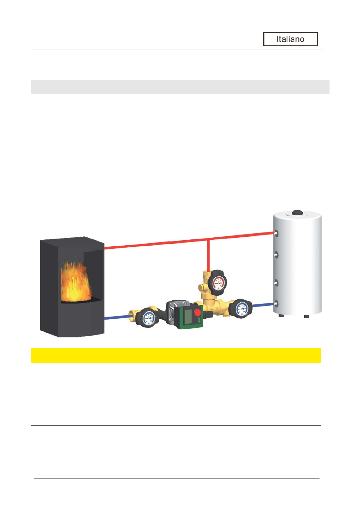
Il set di pompa è costituito da una raccorderia premontata per circuiti di riscaldamento. La pompa
può essere bloccata tramite le valvole a sfera e può essere manutenuta senza dover scaricare
l'acqua dal circuito di riscaldamento.
1 Bypass (alla mandata caldaia)
2 Ritorno accumulatore tampone
3 Ritorno caldaia
A Valvola a sfera, mandata
B Valvola a sfera, ritorno
C Valvola di termoregolazione con bypass automatico
D Pompa riscaldamento
E Valvola a sfera, ritorno
E-6 999612x-mub-ml – V08 2018/02
3
3.2 Funzione
Set di pompe RHT / RHK per l'innalzamento della temperatura di ritorno
Aree di impiego:
AVVISO
Disturbo di funzionamento
Descrizione del prodotto
Grazie al set di pompa, si evita di scendere sotto il punto di condensazione nonché la formazione
di catrame all'interno della caldaia.
Il set di pompa è montato tra il accumulatore tampone e il caldaia. La valvola di regolazione
termica apre il ritorno dell'accumulatore solo se il circuito della caldaia ha raggiunto la temperatura
di apertura di 50 °C o 60 °C. Poi la potenza della pompa è disponibile per caricare l'accumulatore.
• per fonti di calore che richiedono un innalzamento temperatura di ritorno, come ad es.
caldaie a combustibile solido, impianti a legna o caminetti e termocamini/stufe
Se la potenza della caldaia viene regolata in modo che superi la temperatura della
caldaia, la caldaia dovrebbe riscaldarsi di 20 K in più rispetto alla temperatura di
apertura del sistema d'innalzamento della temperatura di ritorno. In caso contrario la
caldaia riduce la potenza ancor prima che la valvola termica si apra completamente.
2018/02 999612x-mub-ml – V08 E-7

3
3.3 Valvola di regolazione termica
Temperature:
t
= t
t
= t
tKR > tPR
Descrizione del prodotto
La valvola di regolazione termica consente nella fase di avviamento il funzionamento di un bypass.
t
< t
KR
tKR = t
< t
t
KR
FIX
FIX
BY
1. Fino a quando la temperatura dell'acqua nel
circuito caldaia rimane al di sotto della temperatura
di apertura della valvola di regolazione, viene
bloccato l'accesso all'accumulatore tampone.
La pompa fa circolare l'acqua nel circuito caldaia
oltre il bypass, in tal modo il volume ridotto d'acqua
del circuito caldaia può scaldarsi più rapidamente.
2. Quando il circuito caldaia raggiunge la temperatura
d'apertura della valvola di regolazione, il bypass
riduce la portata ed apre il circuito dell'accu-
mulatore tampone. L'acqua fredda dal ritorno
dell'accumulatore si mescola con l'acqua calda del
circuito caldaia nella valvola di regolazione.
In tal modo la temperatura di ritorno nel circuito
caldaia raggiunge il livello desiderato evitando la
formazione di condensa all'interno della caldaia.
tKR ≥ t
FIX
3. Qualora la temperatura di ritorno dell'accumulatore
tampone superi la temperatura d'apertura,
la valvola di regolazione chiude completamente il
bypass. L'acqua proveniente dal circuito tampone
fluisce quindi direttamente nel circuito caldaia.
tBy = bypass tKR = ritorno caldaia
= ritorno accumulatore tampone t
t
PR
= temperatura di apertura
FIX
E-8 999612x-mub-ml – V08 2018/02
4
4 Montaggio e installazione [esperto]
AVVISO
Danni materiali
AVVISO
Danni materiali
4.1 Accessorio: raccordo ad anello tagliente (non fornito in dotazione)
Montaggio e installazione [esperto]
Per il montaggio sicuro dell'impianto, il luogo di montaggio deve essere asciutto, staticamente
stabile, nonché protetto da gelate e dalle radiazioni UV.
Montare la pompa sempre sul ritorno della caldaia perché si potrebbe danneggiare a causa
delle temperature di mandata elevate.
Il collegamento all'impianto di riscaldamento può essere effettuato velocemente, a tenuta di
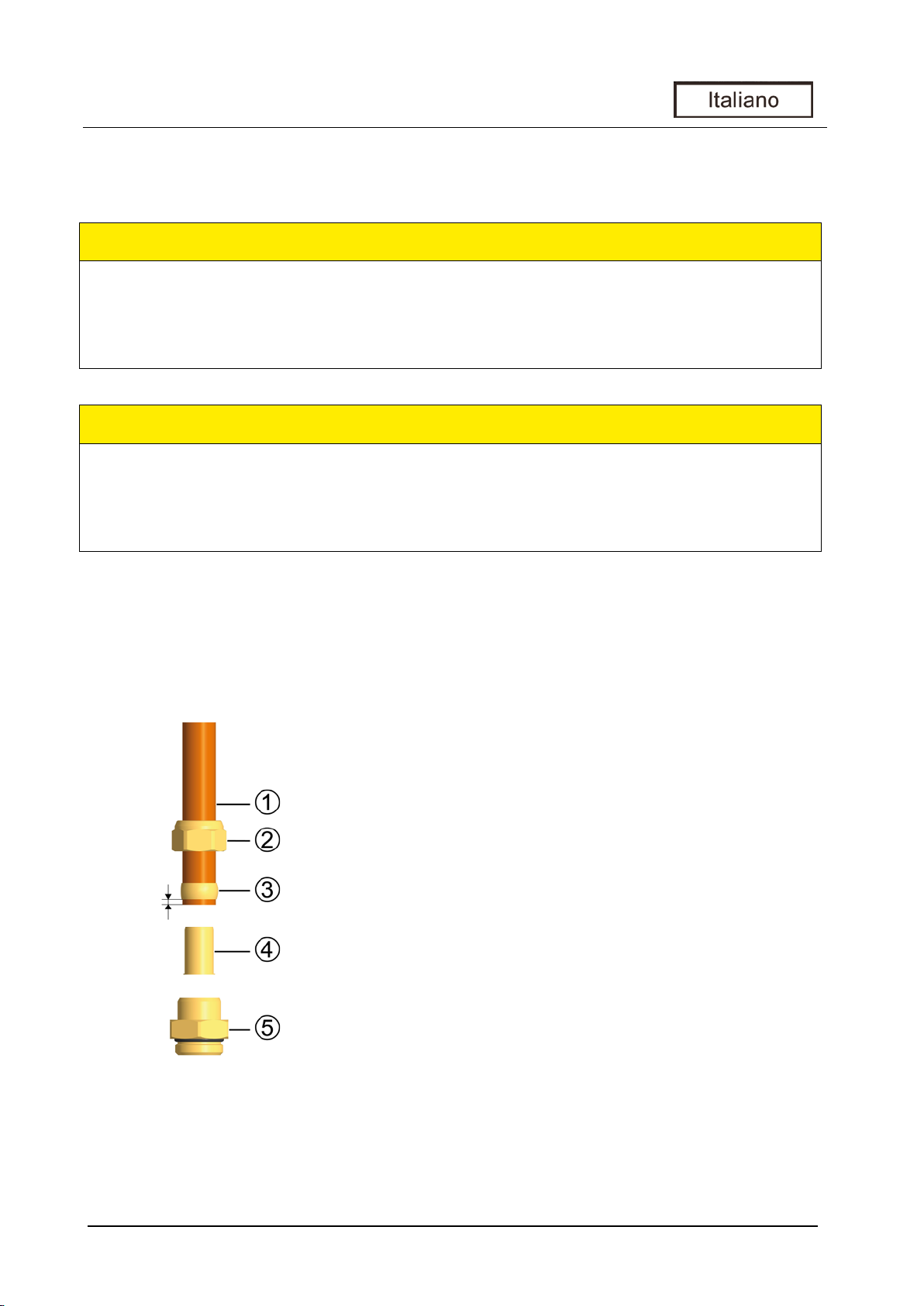
pressione e senza saldature utilizzando i raccordi ad anello taglienti disponibili come opzione.
1. Spingere il dado per raccordo ② e l'anello tagliente ③
nel tubo di rame ①. Per garantire una trasmissione di
forza e una tenuta sicure, il tubo deve fuoriuscire
dell'anello tagliente di almeno 3 mm.
2. Spingere la boccola ④ nel tubo di rame.
3. Introdurre il tubo di rame con i singoli elementi
inseriti (②, ③ e ④) il più possibile nella sede del
raccordo ad anello tagliente ⑤.
4. Avvitare bene il dado per raccordo ② manualmente.
5. Stringere i dadi per raccordo ② per un giro intero.
Per non danneggiare l'anello di tenuta, evitare una
Non compresi nel contenuto della
2018/02 999612x-mub-ml – V08 E-9
fornitura!
torsione eccessiva della sede del raccordo ad anello
tagliente ⑤.

4
4.2 Montaggio
Variante di montaggio A
Variante di montaggio B
Accessori opzionali per il montaggio nei manicotti ½" delle valvole a sfera
Montaggio e installazione [esperto]
La variante di montaggio B permette di bloccare facilmente il generatore di calore senza l'impiego
di ulteriori valvole d'intercettazione. Inoltre necessario: guarnizione, elemento filettato, avvitamento
pompe
Cod. art. 566001 Guaina a immersione (come punto di misura)
Cod. art. 2260 Valvola con controdado per il svuotamento del circuito caldaia
E-10 999612x-mub-ml – V08 2018/02

5
5 Dati tecnici
Set di pompa
RHT - DN 20
RHT - DN 25
RHK - DN 25
Dimensioni
Idraulica
Materiali
Dati tecnici
Altezza totale
Larghezza totale
112 mm 128 mm 140 mm
337 mm 428 mm 452 mm
Attacchi ¾" fil. femmina 1" fil. femmina 1" fil. femmina
Pressione max. 6 bar 6 bar 6 bar
Temperatura max. 110 °C 110 °C 110 °C
Valore Kvs [m3/h] 3,2 7,4 5,7
Campo di impiego per pompe 6 m 30 kW (1300 l/h) 53 kW (2285 l/h) 47,5 kW (2045 l/h)
Temperatura di apertura a seconda della versione: 50 °C / 60 °C, Δt = 20 K
Raccorderia Ottone
Guarnizioni EPDM / NBR
2018/02 999612x-mub-ml – V08 E-11

5
5.1 Perdita di pressione e curve caratteristiche delle pompe
Pressione [m di colonna d'acqua]
Dati tecnici
Pressione [kPa]
Portata [l/h]
Fornitura: Vedi l'ultime pagine di queste istruzioni.
E-12 999612x-mub-ml – V08 2018/02

5
Lieferumfang [Fachmann] /
Scope of delivery [Specialist]
/
Volume de livraison [Expert] /
Entrega [técnico]
/ Dotazione [esperto]
HINWEIS /
NOTICE /
AVISO /
AVIS /
AVVISO
DE:
EN:
ES:
FR:
IT:
RHT - DN 20 (9602x)
Dati tecnici
Reklamationen und Ersatzteilanfragen/-bestellungen werden ausschließlich unter Angabe
der Seriennummer bearbeitet!
Die Seriennummer befindet sich auf dem Rücklaufrohr. /
Complaints and requests/orders of spare parts will only be processed with information on
the serial number!
¡Reclamaciones y demandas/pedidos para piezas de recambio son tramitados únicamente
con indicación del número de serie!
The serial number can be found on the return pipe.
El número de serie se encuentra en el tubo de retorno. /
/
Réclamations et demandes/commandes de pièces de rechange ne sont traitées que si le
numéro de série est indiqué !
Reclami e richieste/ordini di ricambi vengono elaborati esclusivamente se riportano
l’indicazione del numero di serie! ll numero di serie si trova sul tubo di ritorno.
Le numéro de série se trouve sur le tube de retour.
/
2018/02 999612x-mub-ml – V08 E-13

5
RHT - DN 25 (9612x)
Pumpe /
Pump
/ Circulateur /
Bomba
/ Pompa
Art. Nr. /
Item no.
/ N° d'article /
Nº de art.
/ Cod. art.
RHT - DN 20 (9602x)
RHT - DN 25 (9612x)
Dati tecnici
Wilo-Yonos PARA RS 15/6-RKA E1236036
Wilo-Stratos PICO 15/1-6 E1239615
Grundfos UPM3 Auto L 15-70 PP3 E1212360
Grundfos Alpha2 15-60 E121221
Wilo-Yonos PARA RS 25/6-RKA E1236046
Wilo-Stratos PICO 25/1-6 E1239625
Grundfos UPM3 Auto L 25-70 PP3 E1212460
Grundfos Alpha2 25-60 E121391
E-14 999612x-mub-ml – V08 2018/02

5
Dati tecnici
2018/02 999612x-mub-ml – V08 E-15

PAW GmbH & Co. KG
Böcklerstraße 11
D-31789 Hameln, Germany
999612x-mub-ml – V08 2018/02
Telefon: +49 (0) 5151 9856 - 0
Telefax: +49 (0) 5151 9856 98
www.paw.eu
 Loading...