

PAW HeatBloC MC 41 DN 25, HeatBloC MC 41 DN 32 Installation And Operation Instructions Manual

PAW GmbH & Co. KG
Installation and Operation Instructions
HeatBloC MC41
DN 25 / DN 32
Böcklerstr. 11, D-31789 Hameln, Germany
Phone: +49-5151-9856-0, Fax: +49-5151-9856-98
E-mail: info@paw.eu, Web: www.paw.eu
2017/02 99453x013x-mub-en – V02 1

1
General Information
Item no. 99453x013x-mub-en – Version V02 – Issued 2017/02
Translation of the original instructions
We reserve the right to make technical changes without notice!
Printed in Germany – Copyright by PAW GmbH & Co. KG
2 99453x013x-mub-en – V02 2017/02
PAW GmbH & Co. KG
Böcklerstr. 11
D-31789 Hameln, Germany

1
General Information
Contents
1 General Information ......................................................................................................... 4
1.1 Scope of these instructions .......................................................................................... 4
1.2 Designated use ............................................................................................................ 4
2 Safety instructions ........................................................................................................... 5
3 Product description .......................................................................................................... 6
3.1 Equipment .................................................................................................................... 6
3.2 Function ....................................................................................................................... 7
3.3 Pump [specialist] .......................................................................................................... 8
3.3.1 Pump settings Grundfos UPM3 Hybrid .................................................................. 8
3.3.2 Pump settings Wilo-Yonos PARA RSTG ............................................................... 8
3.4 Check valve ................................................................................................................. 9
4 Change of the flow line [specialist] ................................................................................. 10
5 Assembly and installation [specialist] .............................................................................. 11
5.1 Installation and commissioning of the HeatBloC ......................................................... 11
5.2 Cabling ....................................................................................................................... 14
5.3 Accessories ................................................................................................................ 16
5.3.1 Connection set (not included in the scope of delivery) ......................................... 16
5.3.2 Communication set (not included in the scope of delivery) .................................. 16
5.3.3 Cutting-ring compression fitting (not included in the scope of delivery) ................ 17
5.3.4 Wall bracket set for wall assembly (not included in the scope of delivery) ........... 17
6 Scope of delivery [specialist] .......................................................................................... 18
6.1 Insulation and controller DN 25 .................................................................................. 18
6.2 Hydraulics DN 25 ....................................................................................................... 19
6.3 Insulation and controller DN 32 .................................................................................. 20
6.4 Hydraulics DN 32 ....................................................................................................... 21
7 Technical data ............................................................................................................... 22
7.1 Dimensional drawing DN 25 ....................................................................................... 23
7.2 Dimensional drawing DN 32 ....................................................................................... 23
7.3 Pressure drop and pump characteristic curves DN 25 ................................................ 24
7.4 Pressure drop and pump characteristic curves DN 32 ................................................ 24
2017/02 99453x013x-mub-en – V02 3

1
General Information
1 General Information
Carefully read these instructions before installation and commissioning.
Save these instructions in the vicinity of the installation for future reference.
1.1 Scope of these instructions
These instructions describe the function, installation, commissioning and operation of the
direct (unmixed) HeatBloC MC41 DN 25 and DN 32.
For other components of the installation, such as the pump, the controller or the modular
distribution manifold, please observe the instructions of the corresponding manufacturer.
The chapters called [specialist] are intended for specialists only.
1.2 Designated use
The HeatBloC may only be used in heating circuits taking into consideration the technical limit
values indicated in these instructions.
The HeatBloC must
not be used in drinking water applications.
Improper usage of the HeatBloC excludes any liability claims.
Only use PAW accessories with the HeatBloC.
This product complies with the relevant directives and is therefore labelled with the CE mark.
The Declaration of Conformity is available upon request. Please contact the manufacturer.
The wrapping materials are made of recyclable materials and can be disposed of with
recyclable materials.
4 99453x013x-mub-en – V02 2017/02

2
CAUTION
Personal injury and damage to property!
not
NOTICE
Material damage due to mineral oils!
Safety instructions
2 Safety instructions
The installation and commissioning as well as the connection of electrical components require
technical knowledge commensurate with a recognised vocational qualification as a fitter for
plumbing, heating and air conditioning technology, or a profession requiring a comparable level
of knowledge [specialist].
The following must be observed during installation and commissioning:
• relevant local and national regulations
• accident prevention regulations of the professional association
• instructions and safety instructions of this manual
The HeatBloC must only be used in heating circuits filled with heating water
according to VDI 2035 / Ö-Norm H 5195-1.
The HeatBloC must
Mineral oil products cause lasting damage to seals made of EPDM, whereby the sealant
properties get lost. We do not assume liability nor provide warranty for damage to property
resulting from sealants damaged in this way.
It is imperative to avoid that EPDM gets in contact with substances containing mineral
oils.
Use a lubricant based on silicone or polyalkylene and free from mineral oils, such as
Unisilikon L250L and Syntheso Glep 1 of the Klüber company or a silicone spray.
be used in drinking water applications.
2017/02 99453x013x-mub-en – V02 5

3
Product description
3 Product description
The HeatBloC is a preassembled group of fittings for heating circuits. The integrated pump can
be isolated by means of ball valves and can thus be maintained without draining of the system.
The nominal value for the differential pressure between the flow and the return is adjusted at the
controller. On this basis, the controller regulates the pump. Thus, the hydraulic balancing at the
distribution manifold is assured and an energy-saving operation of the pump is guaranteed at
any time.
The PAW HeatBloC must be either installed on a PAW modular distribution manifold or a PAW
wall bracket.
For the function of a MC system, one connection set (wall power supply, item no. 1398700) is
necessary. The connection set is not included in the scope of delivery.
3.1 Equipment
A-1 Flow to the consumer circuit
A-2 Flow ball valve with temperature
sensor T
and thermometer
V
B Heating pump
C-1 Flow from the heat generator
C-2 Return to the heat generator
D-1 Check valve, can be opened
D Return pipe
E Design insulation according to
EnEV directive
F-2 Return ball valve with temperature
sensor T
and thermometer
R
F-1 Return from the consumer circuit
G Differential pressure sensor
H Controller MCom
6 99453x013x-mub-en – V02 2017/02

3
MC41 – Direct HeatBloC
Application range:
Product description
3.2 Function
In the case of the direct or unmixed HeatBloC,
the flow of the heat generator is pumped directly
through the heating circuit.
• Boiler charging
• Storage tank charging and discharging
• Radiators
2017/02 99453x013x-mub-en – V02 7

3
Product description
3.3 Pump [specialist]
The pump can be completely isolated. It can be replaced and maintained without draining the
HeatBloC. Close the ball valves (A-2, C-1) above and beneath the pump.
The pump has been correctly adjusted at the factory. In the case of a breakdown of the control
(no PWM signal), the pump runs at maximum rotation speed. To assure a proper functioning of
the heating circuit, the pump must be set as follows:
• PWM profile (heating)
3.3.1 Pump settings Grundfos UPM3 Hybrid
The following code must appear on the pump display. The code can be verified by briefly
pressing the push button. Please observe the separate instructions of the pump!
Yellow
Off
Off
Yellow
Red
3.3.2 Pump settings Wilo-Yonos PARA RSTG
The rotary knob of the pump must be set to the following symbol.
The LED ring is illuminated in orange. Please observe the separate
instructions of the pump!
8 99453x013x-mub-en – V02 2017/02

3
Operation
Filling, draining, venting
Product description
3.4 Check valve
The HeatBloC is equipped with a check valve in the return pipe. The check valve can be
opened manually.
During operation, the marking must be directed to "Z".
The check valve is closed.
Flow only in the direction of the arrow.
For filling, draining and venting the installation, the marking
must be directed to "A".
The check valve is open.
Flow in both directions.
2017/02 99453x013x-mub-en – V02 9

4
Attention:
4 Change of the flow line [specialist]
Change of the flow line [specialist]
1. Dismount the temperature sensors of the
ball valves (A-2 and F-2).
2. Unscrew both nuts of the sensor (G).
3. Unscrew the nuts of the ball valves (A-2
and F-2) above the pump or the return
pipe.
4. Mount the return ball valve above the
pump and the flow ball valve above the
return pipe.
5. Interchange the flow and the return line.
Please observe the position of the
opening mechanism of the check valve in
the return pipe (see figure).
6. Mount the sensor (G) between the ball
valves.
The ground lug of the sensor
points forward. The banderole indicates
on which side of the sensor housing the
pump must be fixed (see figure on the
left).
7. Flatten the ground lug.
8. Mount the temperature sensors T
into the ball valves.
and TV
R
Observe the correct attribution:
Red = Flow
Blue = Return
10 99453x013x-mub-en – V02 2017/02

5
NOTICE
Damage to property!
Assembly and installation [specialist]
5 Assembly and installation [specialist]
The PAW HeatBloC must be either installed on a PAW modular distribution manifold or a PAW
wall bracket. Please observe the separate instructions!
The location of installation must be dry, load-carrying, frost-proof and protected against
ultraviolet radiation in order to prevent material damage of the installation.
5.1 Installation and commissioning of the HeatBloC
The HeatBloC MC can be mounted on a PAW modular distribution manifold.
Consumer circuit
Return
Flow
Consumer circuit
Return
Flow
2017/02 99453x013x-mub-en – V02 11
Return
Heat generator
Flow

5
NOTICE
(top view)
1
2
3
(side view)
Assembly and installation [specialist]
Verify if the grounding cable holds securely in place at the differential pressure sensor!
The ground lug points in the direction of the banderole.
Carry out the following mounting instructions in parallel at each heating circuit of the
system.
1. Remove the station from the packaging.
2. Note regarding HeatBloC with Wilo pump:
Dismount the insulating front shell of the
controller and push the insulating back
shell backwards.
3. Take off the thermometer handles and
remove the insulating front shells.
4. Push the insulating back shell backwards.
5. Unscrew the nuts on the lower
connections of the HeatBloC and take out
Flange
the sealing rings.
6. Put the two nuts over the flanges of the
distribution manifold.
Nut
Flange
12 99453x013x-mub-en – V02 2017/02

5
Sealing ring
Assembly and installation [specialist]
7. Put the sealing rings on the sealing
surfaces.
8. Put the HeatBloC onto the two nuts.
9. Tighten the nuts. Make sure that the nuts
do not get jammed and that the sealing
rings do not slip.
10. Connect the HeatBloC to the installation
by using the pipes. The installation to the
piping must be carried out without any
tension.
11. Repeat these steps for all the HeatBloCs
that are mounted.
12. Fill and vent the installation.
13. Carry out a pressure test and check all
thread connections.
14. Check the position of the check valve:
during operation, the marking must be
directed to "Z" (see page 9).
15. Mount the insulating back shell.
16. Connect the power supply of the pump to
the heating controller.
17. Flush the installation.
18. Mount the insulating front elements.
19. Mount the insulating front and back shell
of the distribution manifold.
2017/02 99453x013x-mub-en – V02 13

5
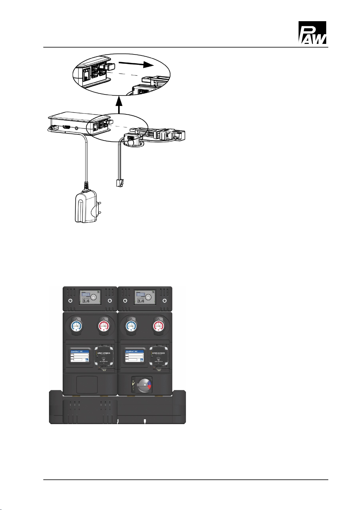
5.2 Cabling
Assembly and installation [specialist]
1. Loosen the screws of the controller insulation.
2. Dismount the insulating front shell of the
Optional communication
set
3. Connect the wall power supply to the
socket X6.2 (see below) at the last (right)
controller.
controller.
4. Connect the bus line from controller 1 to
controller 2 in the socket X6.1.
As the two sockets of the bus line (X6.1 and
X6.2) are connected in parallel, the position
has no importance.
5. Repeat these steps for all the HeatBloCs.
6. Remove the bus line from the last
controller. Keep the bus line as spare part.
X1 X2 X3 X4 X5 X6.1 X6.2
X1 Not used X4 Temperature sensor TV, flow,
red marking
X2 PWM signal of the pump X5 Differential pressure sensor
X3 Temperature sensor TR, return,
blue marking
X6.1
X6.2
Supply voltage or bus line
(connected in parallel and therefore
interchangeable)
14 99453x013x-mub-en – V02 2017/02
5
Assembly and installation [specialist]
7. If you do not mount the
communication set, continue at
point 11.
8. If you additionally mount the
optional communication set, run the
bus line of the communication set
to the first (left) controller. For this
purpose, disconnect the plug of the
bus line from the mini PC of the
communication set.
9. Make sure that the plug does not
get wet.
10. Mount the optional communication
set now. Please observe the
separate instructions of the
communication set!
11. Carry out the electrical
commissioning of the controllers
(see controller instructions).
12. Carry out the electrical
commissioning of the
communication set (see instructions
of communication set).
13. Mount the insulating front shell of
the controller.
14. Screw the screws in the controller
insulation.
2017/02 99453x013x-mub-en – V02 15

5
Assembly and installation [specialist]
15. Please fill in the enclosed insert
and fix it on the insulation:
Type: Type of the heating circuit,
f. ex. MC41
MC41
Name: Type of application,
f. ex. storage tank charging
Storage tank charging
No.: Number of the heating circuit
2
according to the controller
instructions, f. ex. 2
5.3 Accessories
5.3.1 Connection set (not included in the scope of delivery)
For the connection of the MCom controllers to the power supply one connection set (wall power
supply, item no. 1398700) is mandatory, regardless of the number of heating circuits.
5.3.2 Communication set (not included in the scope of delivery)
The communication set with insulated housing can be mounted on the distribution manifold or
on the wall using the enclosed mounting rail. It is connected with the controllers via a bus line.
The internal mini PC is equipped with a power supply unit to assure the power supply and
establishes its own local WLAN network. With a smartphone and the corresponding PAW
MCom app, you can establish a connection with your installation via this WLAN and set
parameters or read out current values.
You will get the app in the App Store for iOS devices and in the Google Play Store for Android
devices entering the search term "PAW MCom".
16 99453x013x-mub-en – V02 2017/02

5
Description
Item no.
Assembly and installation [specialist]
5.3.3 Cutting-ring compression fitting (not included in the scope of delivery)
1. Push the union nut ② and the cutting ring ③ onto the
copper pipe ①. The pipe must protrude at least 3 mm
from the cutting ring in order to ensure the force
transmission and the sealing.
2. Insert the support sleeve ④ into the copper pipe.
3. Insert the copper pipe with the plugged-on individual
3 mm
parts (②, ③ and ④) as far as possible into the
housing of the compression fitting ⑤.
4. First, screw the union nut ② manually.
5. Tighten the union nut ② by rotating one full turn.
Secure the housing of the compression fitting ⑤
against distort, in order to avoid damaging the sealing
ring.
Not included in the
scope of delivery!
5.3.4 Wall bracket set for wall assembly (not included in the scope of delivery)
Wall bracket set DN 25 3422SET
Wall bracket set DN 32 3722SET
2017/02 99453x013x-mub-en – V02 17

6
NOTICE
Scope of delivery [specialist]
6 Scope of delivery [specialist]
Complaints and requests/orders of spare parts will only be processed with information on the
serial number! The serial number is placed on the return pipe of the heating circuit.
6.1 Insulation and controller DN 25
18 99453x013x-mub-en – V02 2017/02

6
Pump
Item number
EEI
Scope of delivery [specialist]
6.2 Hydraulics DN 25
Grundfos UPM3 Hybrid 25-70
Wilo-Yonos PARA RSTG 25/1-7.5
E1212465F < 0.20
E1236247 < 0.21
2017/02 99453x013x-mub-en – V02 19

6
Insulation
Item no.
6.3 Insulation and controller DN 32
Scope of delivery [specialist]
HeatBloC with Grundfos pump
E171593
HeatBloC with Wilo pump
B1715933
20 99453x013x-mub-en – V02 2017/02

6
Pump
Item number
EEI
Scope of delivery [specialist]
6.4 Hydraulics DN 32
Grundfos UPM3 Hybrid 32-70
Wilo-Yonos PARA RSTG 30/1-7.5
E1212565F < 0.20
E1236257 < 0.21
2017/02 99453x013x-mub-en – V02 21

7
MC41
DN 25 (1")
DN 32 (1¼")
Dimensions
Connections
Technical data
Materials
Hydraulics
Technical data
7 Technical data
Centre distance 125 mm 125 mm
Width insulation 250 mm 250 mm
Height insulation 500 mm 557 mm
Installation length 340 mm 400 mm
Connection generator 1½" external thread 2" external thread
Connection consumer 1" internal thread 1¼" internal thread
Opening pressure check valve 200 mm wc, can be opened
Valves and fittings Brass
Gaskets AFM34 / EPDM
Insulation EPP, EnEV conform
Maximum pressure 6 bars
Maximum temperature 110 °C
KVS value [m3/h] 7.2 15.1
22 99453x013x-mub-en – V02 2017/02

7
Technical data
7.1 Dimensional drawing DN 25
7.2 Dimensional drawing DN 32
2017/02 99453x013x-mub-en – V02 23

Differential pressure [m wc]
Differential pressure [kPa]
Differential pressure [m wc]
Differential pressure [kPa]
7.3 Pressure drop and pump characteristic curves DN 25
Flow rate [l/h]
7.4 Pressure drop and pump characteristic curves DN 32
Flow rate [l/h]
PAW GmbH & Co. KG
Böcklerstraße 11
D-31789 Hameln, Germany
99453x013x-mub-en – V02 2017/02
Phone: +49 (0) 5151 9856 - 0
Fax: +49 (0) 5151 9856 - 98
www.paw.eu
 Loading...