


PAW GmbH & Co. KG
DN 25
DN 32
Installation and Operation Instructions
HeatBloC K34
DN 25 / DN 32
Böcklerstr. 11, D-31789 Hameln, Germany
Phone: +49-5151-9856-0, Fax: +49-5151-9856-98
E-mail: info@paw.eu, Web: www.paw.eu
2017/01 993x063x-mub-en – V01 1

1 General Information
Item no. 993x063x-mub-en – Version V01 – Issued 2017/01
Translation of the original instructions
We reserve the right to make technical changes without notice!
Printed in Germany – Copyright by PAW GmbH & Co. KG
PAW GmbH & Co. KG
Böcklerstraße 11
31789 Hameln, Germany
2 993x063x-mub-en – V01 2017/01

1 General Information
Contents
1 General Information ......................................................................................................... 4
1.1 Scope of these instructions .......................................................................................... 4
1.2 Designated use ............................................................................................................ 4
2 Safety instructions ........................................................................................................... 5
3 Product description .......................................................................................................... 6
3.1 Equipment .................................................................................................................... 6
3.2 Function ....................................................................................................................... 7
3.2.1 Check valve and non-return valve ......................................................................... 8
3.2.2 Pump [specialist] ................................................................................................... 9
3.2.3 3-way mixing valve [specialist] .............................................................................. 9
3.3 Accessories: Actuator (optional) ................................................................................. 13
4 Assembly and installation [specialist] .............................................................................. 14
4.1 Installation and commissioning of the HeatBloC ......................................................... 14
4.2 Accessories: Cutting-ring compression fitting (not included in the scope of delivery) .. 17
5 Scope of delivery [specialist] .......................................................................................... 17
5.1 Spare parts DN 25 ..................................................................................................... 18
5.2 Spare parts DN 32 ..................................................................................................... 19
6 Technical data ............................................................................................................... 20
6.1 Pressure drop and pump characteristic curves DN 25 ................................................ 21
6.2 Pressure drop and pump characteristic curves DN 32 ................................................ 21
2017/01 993x063x-mub-en – V01 3

1 General Information
Carefully read these instructions before installation and commissioning.
Save these instructions in the vicinity of the installation for future reference.
1 General Information
1.1 Scope of these instructions
These instructions describe the installation, commissioning, function and the operation of the
mixed HeatBloC K34 DN 25 and DN 32. For other components of the installation, such as the
pump, the controller or the modular distribution manifold, please observe the instructions of the
corresponding manufacturer. The chapters called [specialist] are intended for specialists only.
1.2 Designated use
The HeatBloC may only be used in heating circuits taking into consideration the technical
limit values indicated in these instructions.
The HeatBloC must not be used in drinking water applications.
Improper usage of the HeatBloC excludes any liability claims.
This product complies with the relevant directives and is therefore labelled with the CE mark.
The Declaration of Conformity is available upon request. Please contact the manufacturer.
Only use PAW accessories with the HeatBloC.
The wrapping materials are made of recyclable materials and can be disposed of
with recyclable materials.
4 993x063x-mub-en – V01 2017/01

2 Safety instructions
CAUTION
Personal injury and damage to property!
The HeatBloC must only be used in heating circuits filled
with heating water according to VDI 2035 / Ö-Norm H 5195-1.
The HeatBloC must not be used in drinking water applications.
NOTICE
Material damage due to mineral oils!
Mineral oil products cause lasting damage to seals made of EPDM, whereby the sealant
properties get lost. We do not assume liability nor provide warranty for damage to property
resulting from sealants damaged in this way.
It is imperative to avoid that EPDM gets in contact with substances containing
mineral oils.
Use a lubricant based on silicone or polyalkylene and free from mineral oils, such as
Unisilikon L250L and Syntheso Glep 1 of the Klüber company or a silicone spray.
2 Safety instructions
The installation and commissioning as well as the connection of electrical components require
technical knowledge commensurate with a recognised vocational qualification as a fitter for
plumbing, heating and air conditioning technology, or a profession requiring a comparable
level of knowledge [specialist].
The following must be observed during installation and commissioning:
relevant local and national regulations
accident prevention regulations of the professional association
instructions and safety instructions of this manual
2017/01 993x063x-mub-en – V01 5

3 Product description
A-1
Flow to the consumer circuit
A-2
Full metal thermometer with
immersion sleeve, integrated
in the ball valve (flow)
B
Heating pump
C
3-way mixing valve with
adjustable bypass 0-50%
C-1
Flow from the heat generator
C-2
Return to the heat generator
C-3
Non-return valve, can be opened
D-1
Check valve, can be opened
D
Return pipe
E
Design insulation
with optimised function
F-2
Full metal thermometer with
immersion sleeve, integrated
in the ball valve (return)
F-1
Return from the consumer circuit
3 Product description
The HeatBloC K34 is a preassembled group of fittings for heating circuits. The pump can be
isolated by means of the ball valves and the mixing valve. The pump can thus be maintained
easily without draining the heating circuit.
The HeatBloC is designed such that it can be directly mounted onto a PAW distribution manifold
or a mounting plate.
With transition connections, the HeatBloCs can also be mounted on modular distribution
manifolds of other dimensions.
3.1 Equipment
6 993x063x-mub-en – V01 2017/01

3 Product description
K34 3-way mixing valve with bypass 0-50 %
The flow temperature of the heating circuit is
controlled by the integrated mixing valve. Hot water
from the boiler and cold return water are mixed to
obtain the desired flow temperature. The mixing
valve is adjusted via an external controller in
combination with the electric actuator.
Due to the premixing rate that must be adjusted
at the bypass of the mixing valve, a certain amount
of cold return water is added to the flow water.
The 3-way actuator can thus work over the whole
adjustment range (0-100%), although only a small
amount of water from the boiler is necessary.
Example: Radiant panel heating systems operate
on a low temperature level with small temperature
differences but with high flow rates. It is therefore
sufficient to "inject" a small amount of hot water
into the "warm" return water.
Application range:
Consumer circuits with a considerably
lower flow temperature than the boiler
flow temperature
Consumer circuits with high flow rates,
f.ex. radiant floor heating and radiant
panel heating systems
3.2 Function
2017/01 993x063x-mub-en – V01 7
3 Product description
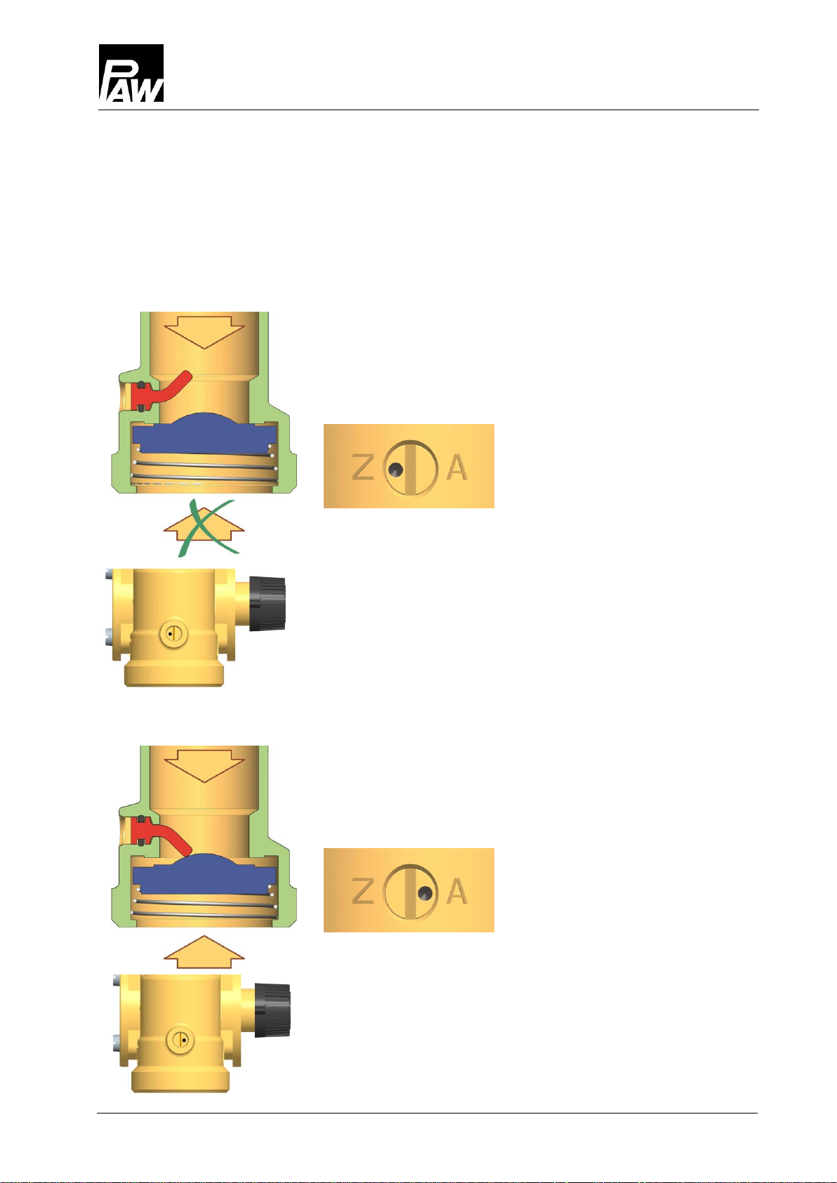
Operation
During operation, the markings must point to "Z".
The check valve and the non-return valve are closed.
Flow only in the direction of the arrow.
Filling, draining, venting
For filling, draining and venting, the markings must be
directed to "A".
The check valve and the non-return valve are open.
Flow in both directions.
3.2.1 Check valve and non-return valve
The HeatBloC is equipped with a check valve (D-1, opening pressure 200 mm wc) in the return
pipe and with a non-return valve (C-3, opening pressure 50 mm wc) in the return of the mixing
valve. The valves can be opened.
8 993x063x-mub-en – V01 2017/01
3 Product description
Position 10:
Passage,
no mixing,
flow temperature consumer =
flow temperature boiler
Position 0:
100% mixing
flow temperature consumer =
return temperature consumer
10
0
Flow of the pump closed
3.2.2 Pump [specialist]
The pump can be completely isolated. It can be replaced and maintained without draining
the heating installation.
Isolation of the pump:
1. Disconnect the expansion tank from the installation.
2. Close the ball valves in the flow and the return (A-2, F-2).
3. Remove the actuator from the mixing valve.
4. Turn the bypass screw of the mixing valve such that the slot is in a vertical position.
5. Turn the nose of the valve cock such that the flow to the pump is closed (for flow on
the right: nose points downward, for flow on the left: nose points to the right; see below).
The mixing valve is now closed and drop tight.
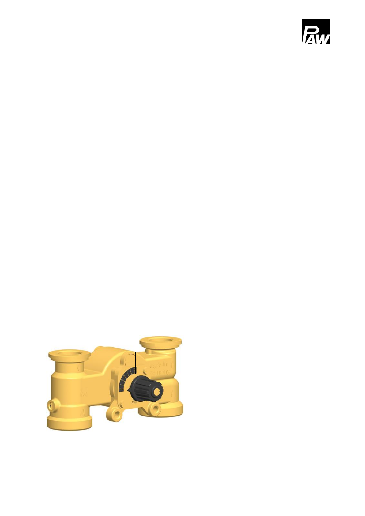
3.2.3 3-way mixing valve [specialist]
The 3-way mixing valve (C), driven by an electric actuator, adjusts the flow temperature of
the consumer circuit to the required value by means of the flow sensor and the controller.
The mixing valve is equipped with a bypass which must be operated separately. Via this
bypass, cold return water is added to the flow of the HeatBloC. This can result in an increase
of the flow rate of the HeatBloC.
Mixing valve with flow on the right:
2017/01 993x063x-mub-en – V01 9

3 Product description
1. During commissioning, determine the optimum bypass position for the operation
of the installation through a trial-and-error process.
If the slot of the bypass screw is
in a vertical position, the bypass
is closed.
If the slot of the bypass screw is in
a horizontal position, the bypass is
completely open. A maximum flow
rate from the return to the flow line
is thus enabled. This adjustment
may be necessary for radiant floor
heating systems which require a
very high water flow volume.
Because of the bypass, the flow
temperature decreases and the
control is affected.
2. Check the position of the bypass during operation. Make sure that the flow rate
is sufficient and that the desired temperature is reached.
10 993x063x-mub-en – V01 2017/01
3 Product description
Change of the flow line [specialist]
Dismounting the mixing valve
1. Take off the thermometer handles (A-2, F-2) and remove the insulating front shell.
2. Take the group of fittings out of the insulating back shell.
3. Dismount the mixing valve (C).
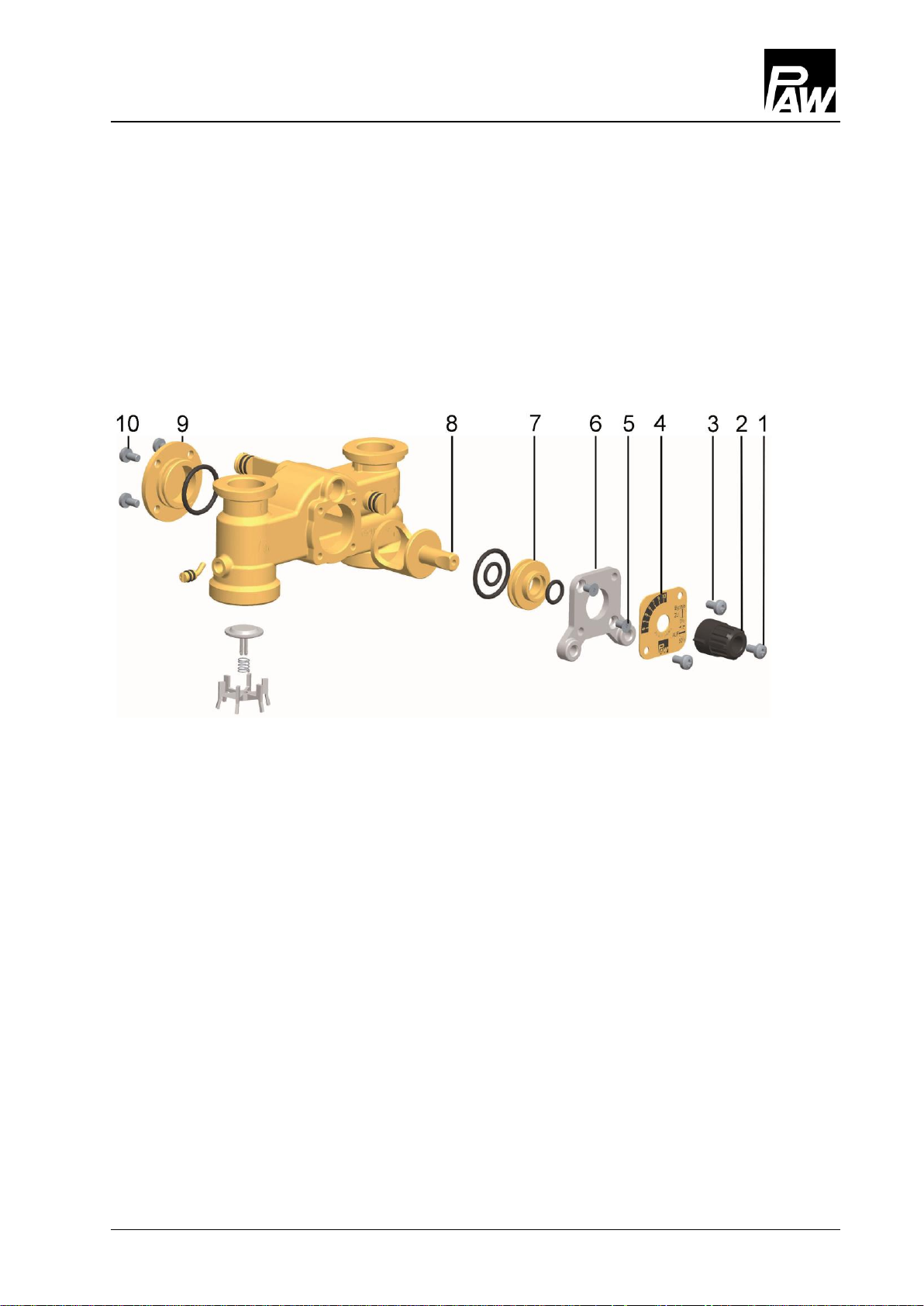
Conversion of the mixing valve
1. Loosen the screw (1).
2. Take off the rotary knob (2) from the cock rod.
3. Loosen the screws (3).
4. Remove the cover plate (4).
5. Loosen the two screws (5).
6. Remove the front plate (6).
7. Extract the sealing bush (7) and the valve cock (8) from the mixing valve housing.
8. Loosen the screws (10) on the rear side of the mixing valve.
9. Take off the cover (9) on the rear side of the mixing valve and fix it on the other side
of the mixing valve by using the screws (10).
10. Insert the sealing bush (7) and the valve cock (8) into the channel of the mixing valve.
11. Fix the front cover (6) by using the screws (5).
2017/01 993x063x-mub-en – V01 11

3 Product description
Mixing valve with flow on the right
Mixing valve with flow on the left
Flow
Flow
12. Turn the cover plate (4) such that the marking PAW is at the bottom
and that the scale is positioned as shown on the figure above.
13. Fix the cover plate (4) by using the screws (3).
14. Put the rotary knob (2) onto the cock rod.
15. Fix the rotary knob (2) on the cock (8) by using the screw (1).
Retrofitting and commissioning of the heating circuit
1. Interchange the return pipe (D) and the flow pipe with the pump (B).
Consider the flow direction of the pump!
Turn the pump head such that the terminal box is directed to the top or to the centre
of the group of fittings.
2. Dismount and interchange the ball valves.
3. Mount the HeatBloC and connect it to the installation.
4. Check all union nuts before commissioning and firmly tighten them if necessary.
5. Mount the insulation only after having carried out a pressure test.
Mount the thermometer handles (A-2, F-2) in a final step.
12 993x063x-mub-en – V01 2017/01

3 Product description
for mixing valve with flow on the right
for mixing valve with flow on the left
Assembly of the actuator for
mixing valves with flow on the right:
1. Turn the rotary knob of the
mixing valve into position 0.
2. Set the actuator to manual mode
by turning the selector switch.
3. Turn the rotary knob of the
actuator to the left to the position
shown on the adjacent figure.
4. Mount the stop bolts.
5. Put the actuator on the adjusting
knob of the mixing valve and the
two stop bolts.
The actuator must be mounted
according to figure 5.
6. Set the actuator to automatic
mode.
Stop bolt
Fig. 1
Fig. 2
Fig. 3
Fig. 4
Fig. 5
blue
blue
blue
red
red
3.3 Accessories: Actuator (optional)
The PAW actuator for weather-compensated control is available as an accessory.
For mixing valves with flow on the left, the scale must be turned by 180°.
2017/01 993x063x-mub-en – V01 13

4 Assembly and installation [specialist]
NOTICE
Damage to property!
The location of installation must be dry, load-carrying, frost-proof and protected
against ultraviolet radiation in order to prevent material damage of the installation.
The HeatBloC can be installed
Option 1:
on a PAW modular distribution manifold.
Heat generator
Consumer circuit
Return
Flow
Flow
Return
4 Assembly and installation [specialist]
The HeatBloC K34 can be mounted on a PAW modular distribution manifold or on a wall
bracket. The modular distribution manifold and the wall bracket are optional accessories
and are thus not included in the scope of delivery.
4.1 Installation and commissioning of the HeatBloC
14 993x063x-mub-en – V01 2017/01

4 Assembly and installation [specialist]
Option 2:
on a mounting plate with
transition thread connections.
Option 3:
directly on a wall bracket
Return
Heat generator
Consumer circuit
Return
Return
Flow
Flow
Flow
Return
Flow
Please observe the separate and respectively corresponding instructions regarding the
installation of the distribution manifold, of the mounting plate and of the wall bracket.
2017/01 993x063x-mub-en – V01 15

4 Assembly and installation [specialist]
1. Take off the thermometer handles
(A-2, F-2) and remove the insulating
front shell of the HeatBloC.
2. Unscrew the nuts on the lower
connections of the HeatBloC
and take out the sealing rings.
If PAW modular distribution manifold
or transition connection is used:
3. Put the two nuts over the flanges.
4. Insert the sealing rings into the nuts.
5. Put the HeatBloC onto the two nuts.
6. Tighten the nuts. Make sure that the
nuts do not get jammed and that the
sealing rings do not slip.
7. Connect the HeatBloC to the
installation by using the pipes.
The installation to the piping must
be carried out without any tension.
8. Connect the pump.
9. Carry out a pressure test and
check all thread connections.
10. Mount the insulating front shell and
the thermometer handles (A-2, F-2).
Flange
(top view)
Nut
1
2
3
Flange
(side view)
Sealing ring
16 993x063x-mub-en – V01 2017/01

5 Scope of delivery [specialist]
Not included in
the scope of delivery!
1. Push the union nut ② and the cutting ring ③ onto the
copper pipe ①. The pipe must protrude at least 3 mm
from the cutting ring in order to ensure the force
transmission and the sealing.
2. Insert the support sleeve ④ into the copper pipe.
3. Insert the copper pipe with the plugged-on individual
parts (②, ③ and ④) as far as possible into the
housing of the compression fitting ⑤.
4. First, screw the union nut ② manually.
5. Tighten the union nut ② by rotating one full turn.
Secure the housing of the compression fitting ⑤
against distort, in order to avoid damaging the
sealing ring.
NOTICE
Complaints and requests/orders of spare parts will only be processed with information on
the serial number!
The serial number is placed on the return pipe of the heating circuit.
4.2 Accessories: Cutting-ring compression fitting (not included in the scope of delivery)
The connection to the heating installation can be carried out fast, pressure-proof
and without soldering if you use the optionally available compression fittings.
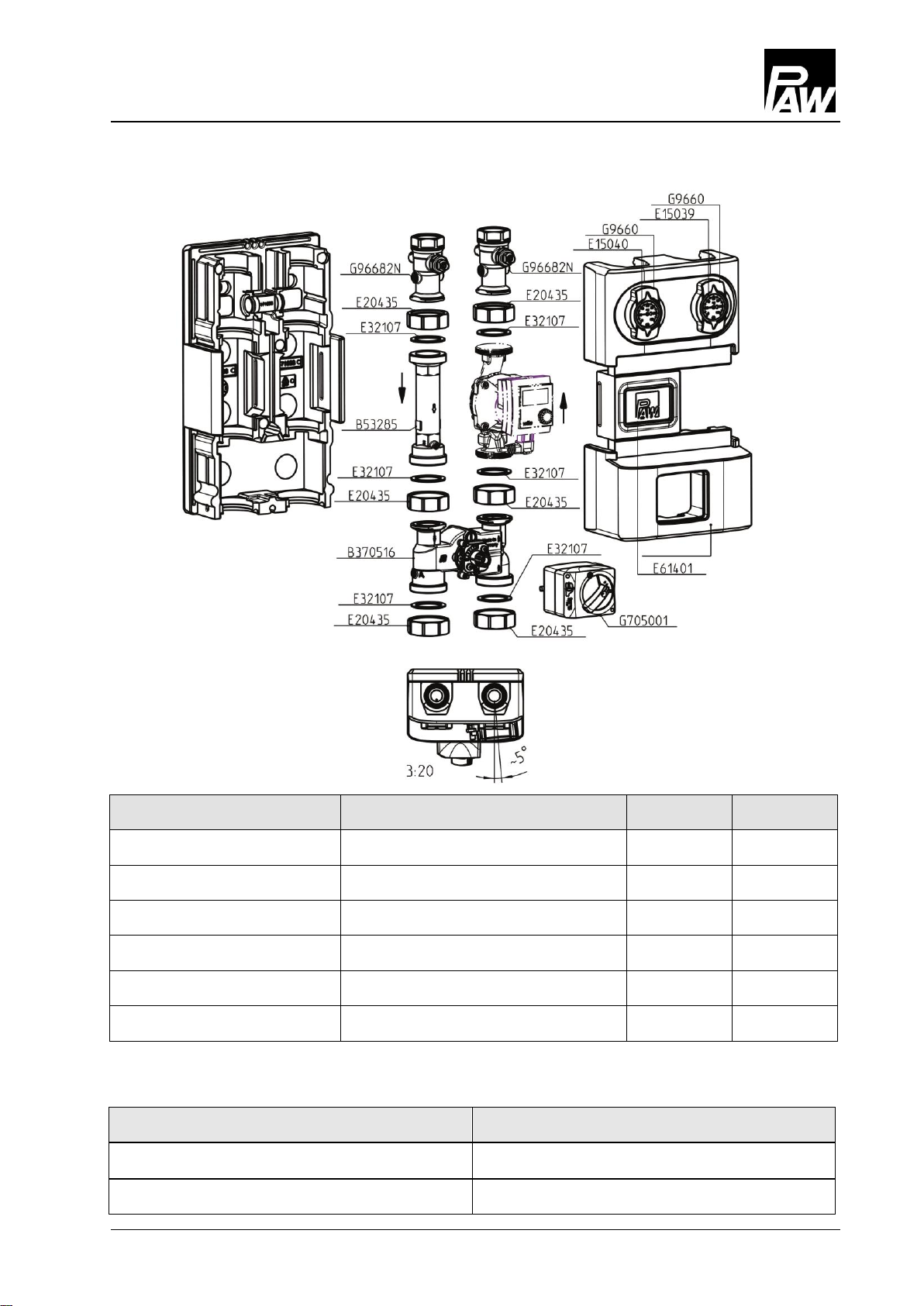
5 Scope of delivery [specialist]
2017/01 993x063x-mub-en – V01 17

5 Scope of delivery [specialist]
Item no. heating circuit*
Pump
Item no.
EEI
36063(M)WY6
Wilo-Yonos PARA RS 25/6-RKA
E1236046
< 0.20
36063(M)WY8
Wilo-Yonos PARA RS 25/7.5-RKA
E1236048
< 0.21
36063(M)WH6
Wilo-Stratos PICO 25/1-6
E1239625
< 0.20
36063(M)GL9
Grundfos UPML 25-95 Auto
E121394
< 0.23
36063(M)GM6
Grundfos UPM3 Auto L 25-70 PP3
E1212460
< 0.20
36063(M)GH6
Grundfos Alpha2.1 25-60
E121391
< 0.17
Description
Item number
Sealing set for mixing valve
37013
Actuator 5 Nm, 230 V, 50 Hz
705001
5.1 Spare parts DN 25
*Heating circuits with an actuator additionally contain a M in the item number, f. ex. 36063MWY6
(without actuator = 36063WY6)
18 993x063x-mub-en – V01 2017/01
5 Scope of delivery [specialist]
Item no. heating circuit*
Pump
Item no.
EEI
39063(M)WY6
Wilo-Yonos PARA RS 30/6-RKA
E1236056
< 0.20
39063(M)WH6
Wilo-Stratos PICO 30/1-6
E1239630
< 0.20
39063(M)WY10
Wilo-Yonos PARA HF 30/0.5-10
E12361510
< 0.20
39063(M)GM6
Grundfos UPM3 Auto L 32-70 PP3
E1212560
< 0.20
39063(M)GH6
Grundfos Alpha2.1 32-60
E121701
< 0.17
39063(M)GL9
Grundfos UPML 32-95 Auto
E121704
< 0.23
Description
Item number
Sealing set for mixing valve
37013
Actuator 5 Nm, 230 V, 50 Hz
705001
5.2 Spare parts DN 32
*Heating circuits with an actuator additionally contain a M in the item number, f. ex. 39063MWY6
(without actuator = 39063WY6)
2017/01 993x063x-mub-en – V01 19

6 Technical data
K34
DN 25 (1")
DN 32 (1¼")
Dimensions
Centre distance (1)
125 mm
125 mm
Width insulation (2)
250 mm
250 mm
Height insulation (3)
383 mm
441 mm
Installation length (4)
340 mm
400 mm
Connections
Outlet (A-1, F-1)
1" int. thread
1¼" int. thread
Inlet (C-1, C-2)
1½" ext. thread
2" ext. thread
Technical data
Opening pressure check valve (D-1)
200 mm wc, can be opened
Opening pressure non-return valve (C-3)
50 mm wc, can be opened
Materials
Valves and fittings
Brass
Gaskets
EPDM
Insulation
EPP
6 Technical data
20 993x063x-mub-en – V01 2017/01

6 Technical data
K34
DN 25 (1")
DN 32 (1¼")
Hydraulics
Maximum pressure
6 bars
6 bars
Maximum temperature
110 °C
110 °C
KVS value [m3/h]
6.0
10.1
Pressure [m wc]
Pressure [kPa]
Flow rate [l/h]
Pressure [m wc]
Pressure [kPa]
Flow rate [l/h]
6.1 Pressure drop and pump characteristic curves DN 25
6.2 Pressure drop and pump characteristic curves DN 32
2017/01 993x063x-mub-en – V01 21

6 Technical data
22 993x063x-mub-en – V01 2017/01

6 Technical data
2017/01 993x063x-mub-en – V01 23

PAW GmbH & Co. KG
Böcklerstraße 11
D-31789 Hameln, Germany
www.paw.eu
Phone: +49 (0) 5151 9856 - 0
Fax: +49 (0) 5151 9856 - 98
993x063x-mub-en – V01 2017/01
 Loading...