

PAW SolexMidi TW, SolexMaxi TW, 6096465, 6095436 Installation And Operation Instruction Manual
Page 1

PAW GmbH & Co.KG
Installation and Operation Instructions
Transfer Stations:
SolexMidi TW - DN 20
SolexMaxi TW - DN 25
[hydraulics]
SolexMidi TW
SolexMaxi TW
Böcklerstr. 11, D-31789 Hameln, Germany
Phone: +49-5151-9856-0, Fax: +49-5151-9856-98
E-mail: info@paw.eu, Web: www.paw.eu
2017/05 99609x4x5-mub-en – V05 1
Page 2

1 General Information
Item no. 99609x4x5-mub-en – Version V05 – Issued 2017/05
Translation of the original instructions
We reserve the right to make technical changes without notice!
Printed in Germany – Copyright by PAW GmbH & Co. KG
PAW GmbH & Co.KG
Böcklerstraße 11
D-31789 Hameln, Germany
2 99609x4x5-mub-en – V05 2017/05
Page 3

1 General Information
Contents
s1 General Information ........................................................................................................... 4
1.1 About these instructions ............................................................................................... 4
1.2 About this product ........................................................................................................ 5
1.3 Designated use ............................................................................................................ 6
2 Safety instructions ............................................................................................................. 7
3 Assembly and installation [specialist] .................................................................................. 9
3.1 Controller connection ................................................................................................. 11
4 Commissioning [specialist] ............................................................................................... 12
4.1 Preparations before flushing and filling ....................................................................... 13
4.2 Flushing and filling the secondary circuit .................................................................... 13
4.3 Flushing and filling the solar circuit ............................................................................. 14
4.4 Parameters: SolexMidi / SolexMaxi with controller SC5.14......................................... 19
5 Maintenance [specialist] ................................................................................................... 20
5.1 Draining the solar station ............................................................................................ 21
5.2 Deinstallation.............................................................................................................. 21
6 Spare parts [specialist] ..................................................................................................... 22
6.1 Spare parts control and insulation SolexMidi TW (6095436) ...................................... 22
6.2 Spare parts hydraulics SolexMidi TW (6095436) ........................................................ 23
6.3 Spare parts control and insulation SolexMaxi TW (6096465) ..................................... 24
6.4 Spare parts hydraulics SolexMaxi TW (6096465) ....................................................... 25
7 Technical data ................................................................................................................. 26
7.1 Dimensional drawing SolexMidi TW ........................................................................... 27
7.2 Dimensional drawing SolexMaxi TW .......................................................................... 27
7.3 Pressure drop characteristics SolexMidi TW .............................................................. 28
7.4 Pressure drop characteristics SolexMaxi TW ............................................................. 28
8 Function of the check valves [Expert] ................................................................................ 29
9 Commissioning report ...................................................................................................... 31
2017/05 99609x4x5-mub-en – V05 3
Page 4

1 General Information
Carefully read these instructions before installation and commissioning.
Save these instructions in the vicinity of the installation for future reference.
DN 20
Item number
Controller
SC5.14
Flow rate
(maximum)
Collector surface
(maximum)
SolexMidi
TW
6095436
1200 l/h
50 m²
DN 25
Item number
Controller
SC5.14
Flow rate
(maximum)
Collector surface
(maximum)
SolexMaxi
TW
6096465
2000 l/h
100 m²
1 General Information
1.1 About these instructions
These instructions describe the functioning, installation, commissioning and operation of the
SolexMidi TW and SolexMaxi TW transfer stations for charging buffer tanks or domestic hot
water tanks. The chapters called [specialist] are intended for specialists only.
For other components of the solar installation, such as pumps, collectors, storage tanks or
expansion tanks, please observe the instructions of the corresponding manufacturer.
4 99609x4x5-mub-en – V05 2017/05
Page 5

1 General Information
1.2 About this product
The station is a premounted group of valves and fittings checked for leakage and used to
transfer the heat from the primary (solar circuit) to the secondary circuit (heating circuit or
domestic hot water circuit).
It contains a preset controller as well as important fittings for the operation of the system:
Ball valves in the primary circuit (flow and return)
Piston valves in the secondary circuit (flow and return)
Check valves to avoid involuntary gravity circulation in the flow and return of the solar
circuit, non return valve in the return of the secondary circuit
Pressure relief valves to prevent inadmissible overpressures in the station
Pressure gauge for displaying the installation pressure in the primary circuit
Vent valves to easily vent the primary circuit and the secondary circuit
Fill and drain valves with caps to flush, fill and drain the primary circuit
A flow meter (FlowRotor) and temperature sensors for heat quantity balancing (primary)
In the heating circuit, the installation must be equipped with a safety group, that can be ordered
separately.
The expansion tank required for operation must be adapted to the size and the requirements of
the installation and must be ordered separately.
The cap-type valve (DN 20: item no. 5302, DN 25: item no. 5301), which is also separately
available, allows the expansion tank to be easily mounted and separated from the solar thermal
system.
The wrapping materials are made of recyclable materials and can be disposed of with
recyclable materials.
2017/05 99609x4x5-mub-en – V05 5
Page 6

1 General Information
When the sun shines, the collectors can become very hot.
The solar fluid in the circuit can heat up to more than 100 °C.
Only flush and fill the solar circuit when the collector temperatures are
below 70 °C.
Schematic structure
SolexMidi / SolexMaxi
Scope of delivery
1.3 Designated use
The station may only be used as a transfer station between the solar and the domestic hot
water circuit or storage tank in solar thermal systems taking into consideration the technical limit
values indicated in these instructions. Due to its design the station must be mounted and
operated as described in these instructions!
Only use PAW accessories with the transfer station.
Improper usage excludes any liability claims.
6 99609x4x5-mub-en – V05 2017/05
Page 7

2 Safety instructions
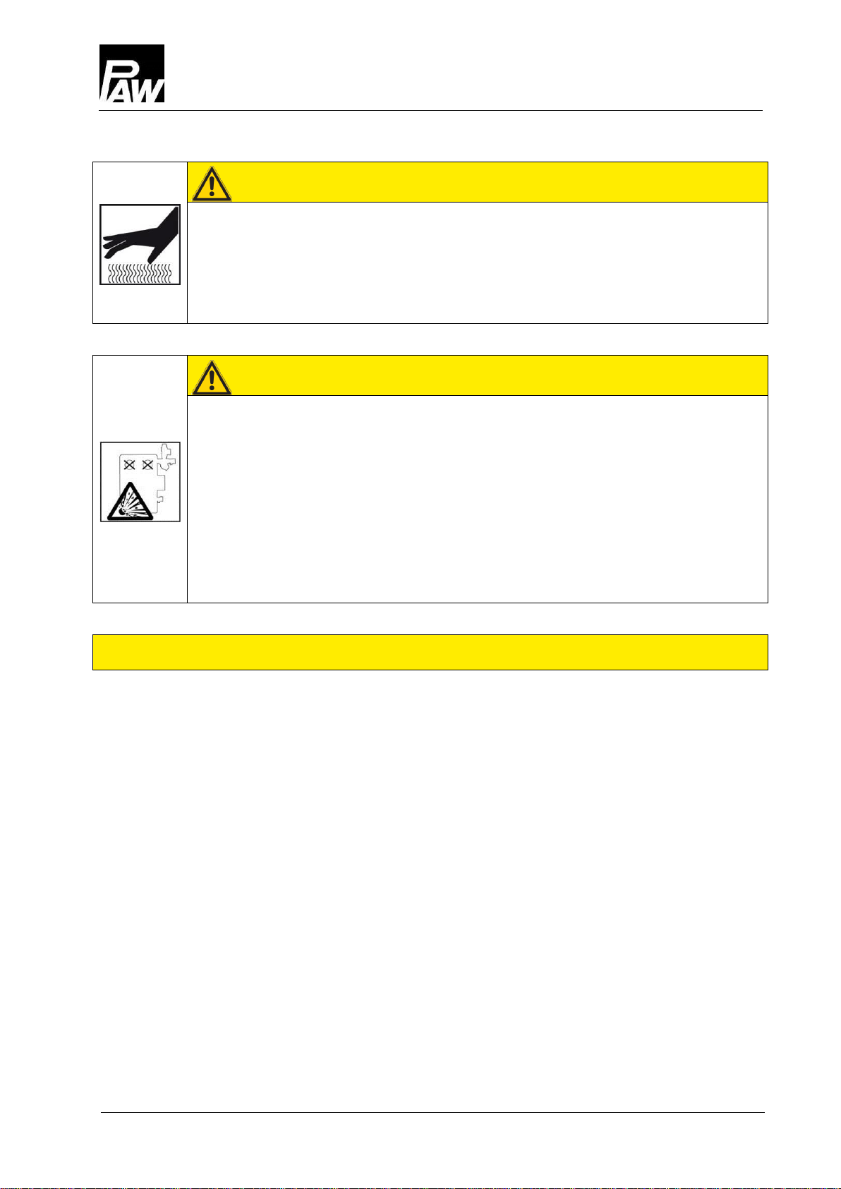
WARNING
Danger of scalding due to vapour escape!
With pressure relief valves there is risk of scalding due to vapour escape.
During installation, check the local conditions and if a discharge line must be
connected to the safety group.
Observe the instructions regarding the pressure relief valve.
The pressures calculated by the installation planner for the expansion tank
and the operating pressure of the installation must be set.
WARNING
Personal injury due to polluted potable water!
The heating water contains harmful substances, that must not be washed into the
domestic hot water circuit.
If the station was used for charging a buffer tank there is still, after draining,
heating water in the valves and fittings and in the pump of the secondary circuit. It
can not be removed without residue.
The station must not be connected to a domestic hot water circuit.
2 Safety instructions
The installation and commissioning as well as the connection of electrical components require
technical knowledge commensurate with a recognised vocational qualification as a fitter for
plumbing, heating and air conditioning technology, or a profession requiring a comparable level
of knowledge [specialist]. The following must be observed during installation and
commissioning:
Relevant local and national regulations
Accident prevention regulations of the professional association
Instructions and safety instructions mentioned in this manual
2017/05 99609x4x5-mub-en – V05 7
Page 8
2 Safety instructions
CAUTION
Risk of burns!
The valves and fittings and the pumps can become heated up to more than
100 °C during operation.
The shell must remain closed during operation.
CAUTION
Personal injury and damage to property due to overpressure!
By closing the two ball valves in the primary circuit you isolate the pressure relief
valve from the heat exchanger. A rise in temperature in the storage tank will
cause high pressures and could result in personal injury or damage to property!
Only close the ball valves for service and maintenance.
If you close the ball valves in case of servicing, do also put the pumps out
of operation and close the ball valves in the secondary circuit.
NOTICE
Material damage due to mineral oils!
Mineral oil products cause lasting damage to seals made of EPDM, whereby the sealant
properties are lost. We do not assume liability nor provide warranty for damage to property
resulting from sealants damaged in this way.
It is imperative to avoid that EPDM gets in contact with substances containing mineral
oils.
Use a silicone- or polyalkylene-based lubricant free of mineral oil such as Unisilikon
L250L and Syntheso Glep 1 from Klüber or a silicone spray.
8 99609x4x5-mub-en – V05 2017/05
Page 9

3 Assembly and installation [specialist]
NOTICE
Material damage due to high temperatures!
Install the fitting group at a sufficient distance from the collector field, since the solar fluid may
be very hot near the collector.
It may be necessary to install an intermediate tank in order to protect the expansion tank.
1. You can use a drilling template in order to facilitate the
installation, which you can find on the station.
2. Copy the mounting holes to the mounting surface.
3. Drill the holes and insert appropriate wall plugs into the
holes.
4. Screw in the screws and let them stick about 4 cm out of
the wall.
5. Remove the station from the packaging.
6. Remove the insulating front shell. Hang the module onto
the screws and tighten the screws.
WARNING
Personal injury due to polluted potable water!
The heating water contains harmful substances, that must not be washed into the
domestic hot water circuit.
If the station was used for charging a buffer tank there is still, after draining,
heating water in the valves and fittings and in the pump of the secondary circuit. It
can not be removed without residue.
The station must not be connected to a domestic hot water circuit.
3 Assembly and installation [specialist]
The location of installation must be dry, load-carrying, frost-proof and protected against
ultraviolet radiation to prevent material damage to the installation. Furthermore, the access to
the control and safety equipment must be guaranteed at all time during operation!
The discharge line of the safety equipment should be guided into a heat-resistant container with
corresponding size. This allows you to avoid uncontrolled discharging into the environment and
to easily refill the circuits!
2017/05 99609x4x5-mub-en – V05 9
Page 10
3 Assembly and installation [specialist]
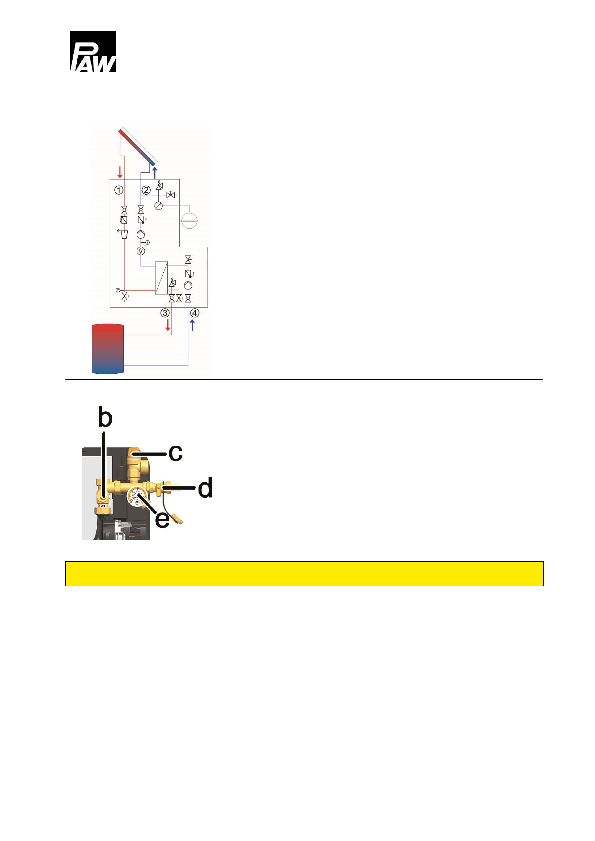
7. Connect the transfer station to the system:
① Solar flow from the collector
② Solar return to the collector
③ Flow to the storage tank
④ Return from the storage tank
The screw connections in the primary circuit of the
SolexMidi have ¾" internal threads and in the secondary
circuit 1" external threads.
The screw connections in the primary circuit of the
SolexMaxi have 1" internal threads and in the secondary
circuit 1¼" external threads.
8. Mount the safety group, consisting of the pressure relief
valve [c], the fill valve [d] and the manometer [e] to the
connection of the return ball valve [b].
9. Connect the pipe for the expansion tank below the
pressure gauge and fix the bracket for the expansion
tank.
During servicing at the expansion tank, we recommend
the installation of a cap valve (DN 20: item no. 5302,
DN 25: item no. 5301) on the expansion tank.
NOTICE
Note regarding the expansion tank
The expansion tank must not be connected while flushing and filling in order to avoid that dirt
particles are washed in.
10. Pressurise the expansion tank as specified by the
manufacturer and connect the expansion tank.
Observe the separate instructions regarding the
expansion tank!
11. Check all screw connections and tighten them if
necessary.
10 99609x4x5-mub-en – V05 2017/05
Page 11
3 Assembly and installation [specialist]
WARNING
Risk to life and limb due to electric shock!
Prior to commencing electrical work on the controller, pull the mains plug!
Only after completing all installation work, plug the mains plug of the
controller into a socket.
This avoids an unintentional start of the motors.
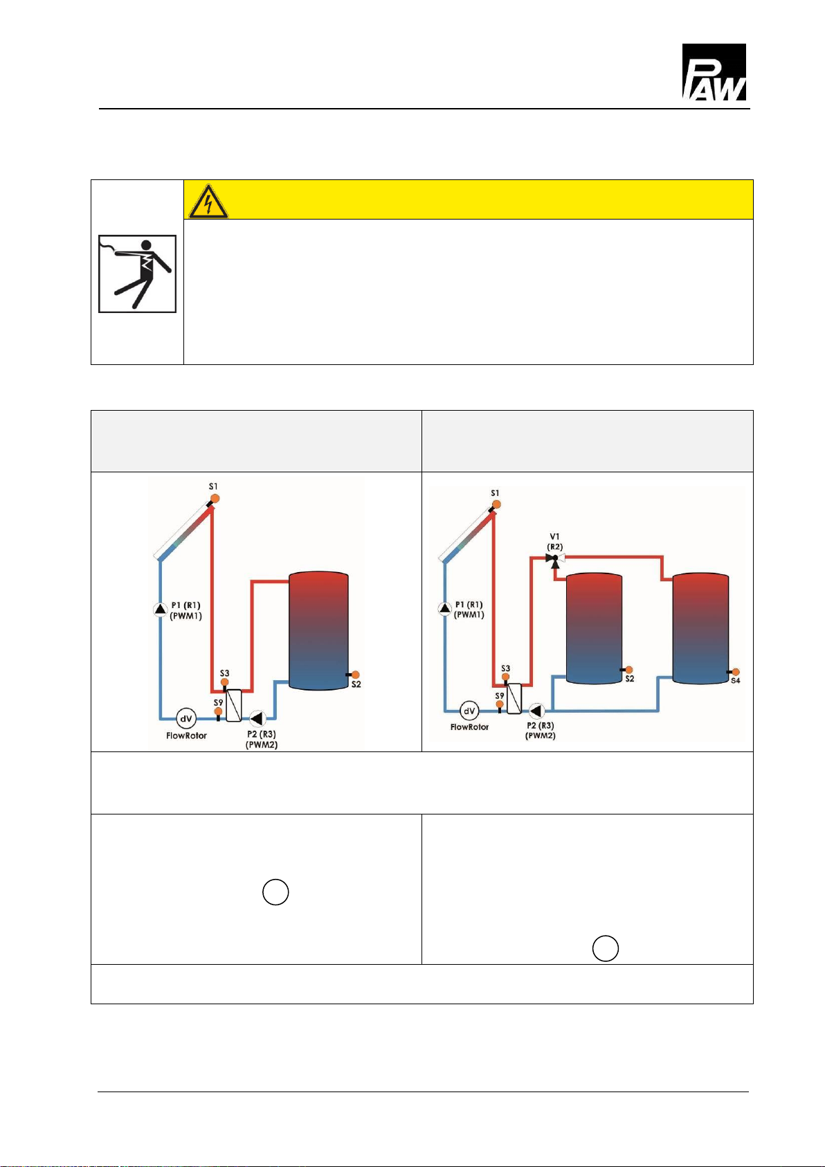
Wiring plan (881) for domestic hot water
systems and heating systems
Wiring plan (882)
for heating systems
Observe the separate instructions regarding the controller SC5.14!
1. Connect the temperature sensors to the controller:
Collector sensor S1
Storage tank bottom: S2
Integrated: S3, S9, (FlowRotor)
Collector sensor S1
Storage tank 1, bottom: S2
Storage tank 2 bottom: S4
(addit. required, item no. E13180)
Integrated: S3, S9, (FlowRotor)
2. Tighten all union nuts and screw connections.
The assembly of the transfer station is now completed and
you can put the station into operation.
dV
dV
3.1 Controller connection
Wiring plan SolexMidi / SolexMaxi
2017/05 99609x4x5-mub-en – V05 11
Page 12

4 Commissioning [specialist]
WARNING
Risk of burns and scalding!
The fittings can heat up to more than 100 °C. Therefore, do not clean or fill the
system with the collectors heated (intense sunshine). Please note that hot solar
fluid can leak from the pressure relief valve when the system pressure is too high!
During venting the solar fluid may escape as vapour and cause scalding!
Only flush and fill the system when the collector temperatures are below
70 °C.
NOTICE
Risk of frost!
It often happens that the solar thermal system cannot be completely drained after flushing.
Thus, there is risk of frost damage when flushing with water. Therefore, do only use the solar
fluid used later to flush and fill the solar installation.
Use a water and propylene glycol mixture with max. 50% of propylene glycol as a solar
fluid.
NOTICE
Note regarding the commissioning
Flush and fill in the following order:
1. Flush the storage tank (to remove scale residues).
2. Fill the secondary circuit.
3. Vent the heat exchanger by means of the pressure relief valve.
4. Flush and fill the solar circuit of the heat exchanger.
5. Flush and fill the collector field.
6. Flush and fill the entire solar circuit.
This guarantees that the dirt particles are not flushed into the heat exchanger or the FlowRotor
and that eventually absorbed heat can be dissipated.
4 Commissioning [specialist]
Observe the following safety instructions regarding the commissioning of the module:
12 99609x4x5-mub-en – V05 2017/05
Page 13

4 Commissioning [specialist]
NOTICE
Note regarding the expansion tank
To prevent that the dirt particles in the solar thermal system are flushed into the expansion
tank, some manufacturers recommend to disconnect the expansion tank from the solar circuit
before flushing and filling. Please observe the instructions of the manufacturer.
Secondary circuit
1. Open the piston valves [C|D].
2. Vent the secondary circuit by operating the fill
and drain valve [A].
Make sure that the electrical components do not
get wet.
3. Fill the secondary circuit by means of the valves
at the domestic hot water tank or at the heating
system.
4. During operation, vent the station at the fill and
drain valve [A] to eliminate air still present in the
heat exchanger.
4.1 Preparations before flushing and filling
4.2 Flushing and filling the secondary circuit
Depending on the application (charging of a storage tank/charging of a buffer tank), the
secondary circuit is filled by means of the valves at the tank or by means of the valves at the
heating system. Make sure that in the first case above only potable water must be used.
In the second case only treated heating water according to VDI 2035 / Ö-Norm H5195-1 must be
used. To avoid that dirt particles are washed into the heat exchanger, shut the ball valves of the
module and wash out the present dirt particles/scale residues before commissioning the tank.
2017/05 99609x4x5-mub-en – V05 13
Page 14

4 Commissioning [specialist]
0°
45°
90°
Check valve is operating,
flow only in flow direction.
Check valve is not operating,
flow in both directions.
Ball valve closed,
no flow.
4.3 Flushing and filling the solar circuit
The fill and drain valves required to flush and fill are integrated in the transfer station.
Make sure not to wash dirt particles that may be present in the system into the heat exchanger
and the expansion tank. Disconnect the expansion tank from the solar circuit during flushing
and filling, if necessary, and only use flush and fill stations with fine filters.
The solar circuit is flushed in the direction of flow. Make sure that the pump in the solar circuit
cannot be switched on.
Ball valve with integrated flow check valve
(normal flow direction in the figure below: downwards)
14 99609x4x5-mub-en – V05 2017/05
Page 15

4 Commissioning [specialist]
The Airstop with manual vent valve is used to vent the solar
installation. To ensure a perfect ventilation of the solar circuit,
the flow velocity must be at least 0.3 m/s in the flow line.
Pipe diameter [mm]
Flow rate at 0.3 m/s
∅ outside
∅ inside
l/h
l/min
15
13
~ 143
~ 2.4
18
16
~ 217
~ 3.6
22
20
~ 339
~ 5.7
28
25
~ 530
~ 8.8
WARNING
Danger of scalding due to vapour escape!
The escaping fluid can have a temperature of more than 100 °C and cause
scalding.
Carefully open the vent plug and close it again, as soon as medium
escapes.
j
Airstop
The air separated from the solar fluid is collected in the upper part of the Airstop and can be
released at the vent plug [j].
Venting the solar thermal system after commissioning
At the beginning, vent the solar installation daily and then weekly or monthly,
depending on the vented air quantity. Thus, an optimum operation of the solar
installation is ensured. Check the system pressure after venting and increase it to the
specified operating pressure, if necessary.
2017/05 99609x4x5-mub-en – V05 15
Page 16

4 Commissioning [specialist]
Primary circuit
1. Switch off the pump in the solar circuit.
2. Disconnect the expansion tank from the solar
installation. This avoids the access of dirt
particles present in the pipes to the expansion
tank. Observe the separate instructions
regarding the expansion tank!
3. The return ball valve [b] must be closed
(90° position, see page 14).
4. Connect the flush and fill station:
- Pressure hose to the fill valve [d]
- Flush hose to the drain valve [g].
5. Open the fill and drain valves [d|g] and put the
flush and fill station into operation.
6. Slowly open and close the return ball valve [b]
during flushing in order to vent the pump section.
7. Flush the solar circuit until the solar fluid exits
without bubbles (see page 15).
8. Close the drain valve [g] with the filling pump
running and increase the system pressure to
about 5 bars. The system pressure can be read
on the pressure gauge [e].
9. Close the fill valve [d] and switch off the pump of
the flush and fill station.
10. Check the pressure gauge to see whether the
system pressure reduces and eliminate leaks
where necessary.
Observe the pressure (max. 6 bars)!
16 99609x4x5-mub-en – V05 2017/05
Page 17

4 Commissioning [specialist]
11. Reduce the pressure on the drain valve [g] to the
operating pressure.
12. Connect the expansion tank to the solar circuit
and set the operating pressure of the solar
thermal system by means of the flush and fill
station (for the required operating pressure, see
instructions of the expansion tank).
13. Close the fill and drain valves [d|g].
14. Put the ball valve [b] into 0° position
(see page 14).
WARNING
Risk to life and limb due to electric shock!
Check if the sensors and the pumps are properly connected to the
controller and if the controller housing is closed.
Only then should the mains plug of the controller be plugged into a socket.
SC5.14
15. Connect the controller to the mains and set the
solar circuit pump in the manual mode to ON
according to the controller instructions.
16. Let the solar pump run at maximum rotation speed
for at least 15 minutes.
Meanwhile vent the solar installation several times
at the vent plug [j] of the Airstop until the solar
fluid exits without bubbles (see page 14).
17. If necessary, increase the system pressure to the
operating pressure.
2017/05 99609x4x5-mub-en – V05 17
Page 18

4 Commissioning [specialist]
18. Remove the hoses of the flush and fill station and
screw the sealing caps onto the fill and drain
valves.
The sealing caps only serve to protect the valves
against dirt. They are not designed to take up high
system pressures. The ball valves must be closed.
19. Mount the insulating front shell.
20. Set to automatic mode on the controller (see
controller instructions).
The commissioning of the solar installation is now
completed.
Please fill in completely the commissioning report
on page 31.
18 99609x4x5-mub-en – V05 2017/05
Page 19

4 Commissioning [specialist]
Preset system (scheme 881) SolexMidi / SolexMaxi
4.4 Parameters: SolexMidi / SolexMaxi with controller SC5.14
The parameters for the sensors and pumps are preset in the controller. If you select and save
another system, the parameters are reset to the factory setting. In this case you need to set the
following parameters in the menu. In this way you make sure that the installation will work
properly. You can find a detailed description for the operation of the controller in the separate
controller manual.
2017/05 99609x4x5-mub-en – V05 19
Page 20

5 Maintenance [specialist]
WARNING
Risk of burns and scalding!
The valves, fittings and solar fluid can reach temperatures of more than 100 °C.
The solar fluid can escape as vapor and cause scalding.
Only carry out maintenance work when the collector temperatures are
below 50 °C.
Wait until the solar fluid has cooled down to max. 50 °C.
Example: SolexMidi
1. Close the ball valves [a|b] and exit the solar fluid at
the fill and drain valve [g]. Make sure that the solar
fluid is collected in a heat-resistant container.
2. Change the faulty part against the new part.
3. Fill the solar circuit as described in 4.3 Flushing and
filling the solar circuit (see page 14).
5 Maintenance [specialist]
Make sure that the system is not under pressure during service and maintenance works at the
station.
20 99609x4x5-mub-en – V05 2017/05
Page 21

5 Maintenance [specialist]
1. Switch off the controller and make sure that a
restart is not possible.
2. Open the check valves in the flow and return ball
valve [a|b], by turning them to position 45°
(see page 14).
3. Connect a heat-resistant hose to the fill valve [g]
of the transfer station.
Make sure that the solar fluid is collected in a
heat-resistant container.
WARNING
Danger of scalding due to hot solar fluid!
The escaping fluid may be very hot.
Place the collecting container so that people standing nearby are not
endangered when the solar installation is being emptied.
4. Open the fill and drain valve [g] of the transfer station.
5. To accelerate draining of the solar circuit, you can open the vent valve,
if present, at the highest point of the solar thermal system.
6. Dispose of the solar fluid observing the local regulations.
5.2 Deinstallation
1. Drain the solar thermal installation as described above.
2. Disconnect the pipe joints with the solar thermal system.
3. Disconnect the cable connections between controllers and sensors
(collector/storage tank).
4. Loosen the fastening screws of the station and take the station off the wall.
5.1 Draining the solar station
2017/05 99609x4x5-mub-en – V05 21
Page 22

6 Spare parts [specialist]
NOTICE
Complaints and requests/orders of spare parts will only be processed with information on the
serial number!
The serial number can be found in the lower right corner of the support sheet in the station.
In case of a complaint, please send us the completely filled commissioning report on
page 31.
6 Spare parts [specialist]
6.1 Spare parts control and insulation SolexMidi TW (6095436)
22 99609x4x5-mub-en – V05 2017/05
Page 23

6 Spare parts [specialist]
6.2 Spare parts hydraulics SolexMidi TW (6095436)
2017/05 99609x4x5-mub-en – V05 23
Page 24

6 Spare parts [specialist]
6.3 Spare parts control and insulation SolexMaxi TW (6096465)
24 99609x4x5-mub-en – V05 2017/05
Page 25
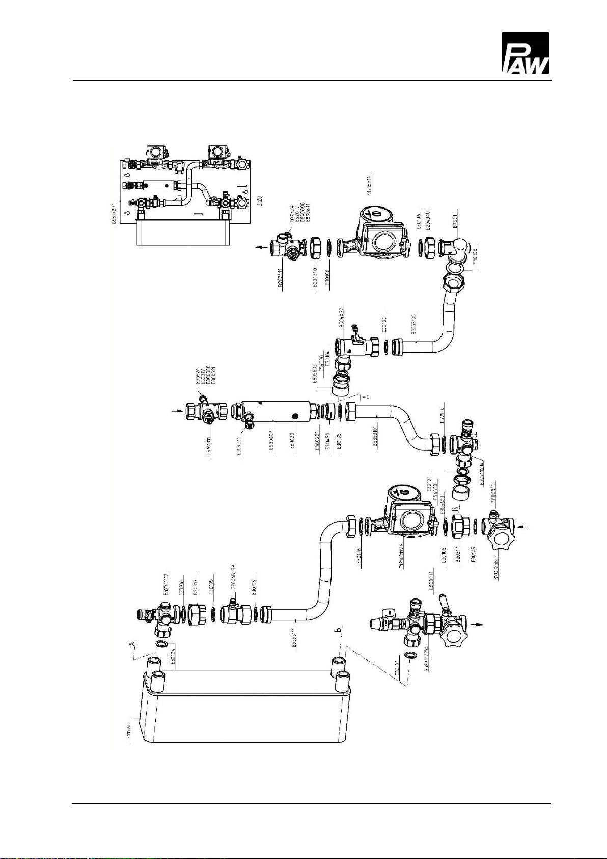
6 Spare parts [specialist]
6.4 Spare parts hydraulics SolexMaxi TW (6096465)
2017/05 99609x4x5-mub-en – V05 25
Page 26
7 Technical data
Dimensions
SolexMidi TW
SolexMaxi TW
Height (total)
795 mm
829 mm
Width (total)
674 mm
674 mm
Depth (total)
298 mm
298 mm
Centre distance, flow/return
120 mm
120 mm
Pipe connections primary
¾" internal thread
1" internal thread
Pipe connections secondary
1" external thread
1¼" external thread
Connection for expansion tank
¾" external thread, flat sealing
Outlet pressure relief valve
¾" internal thread
Operating data
Max. admissible pressure
prim.: 6 bars / sec.: 10 bars
Max. Operating temperature
prim.: 120 °C / sec.: 95 °C
Max. stagnation temperature
140 °C
Max. propylene glycol content
50 %
Operating temperature sensors
-25 °C to +120 °C
Equipment
Pressure relief valve
prim.: 6 bars / sec.: 10 bars
Pressure gauge
0 – 6 bars
Flow rate measurement device
prim.: FlowRotor: 2-50 l/min
Sensors
2 x Pt1000 (mounted), 2 x Pt1000 (enclosed)
Check valves
(integrated in the ball valves)
prim.: 2 x 200 mm wc, can be opened
sec.: 1 x 150 mm wc, can be opened
Material
Valves and fittings
Brass
Gaskets
EPDM
Check valves
Brass
Insulation
EPP, = 0,041 W/(m K)
7 Technical data
26 99609x4x5-mub-en – V05 2017/05
Page 27

7 Technical data
7.1 Dimensional drawing SolexMidi TW
7.2 Dimensional drawing SolexMaxi TW
2017/05 99609x4x5-mub-en – V05 27
Page 28

7 Technical data
Pressure [mWC]
Pressure [kPa]
Flow rate [m³/h]
Pressure [mWC]
Pres
sure [kPa]
Flow rate [m³/h]
7.3 Pressure drop characteristics SolexMidi TW
7.4 Pressure drop characteristics SolexMaxi TW
28 99609x4x5-mub-en – V05 2017/05
Page 29
8 Function of the check valves [Expert]
Within their application range, the check valves in this station prevent unwanted gravity
circulation. The efficiency of the check valves depends on:
the installation height
the temperature difference between the storage tank and the collector
the type of heat transfer medium
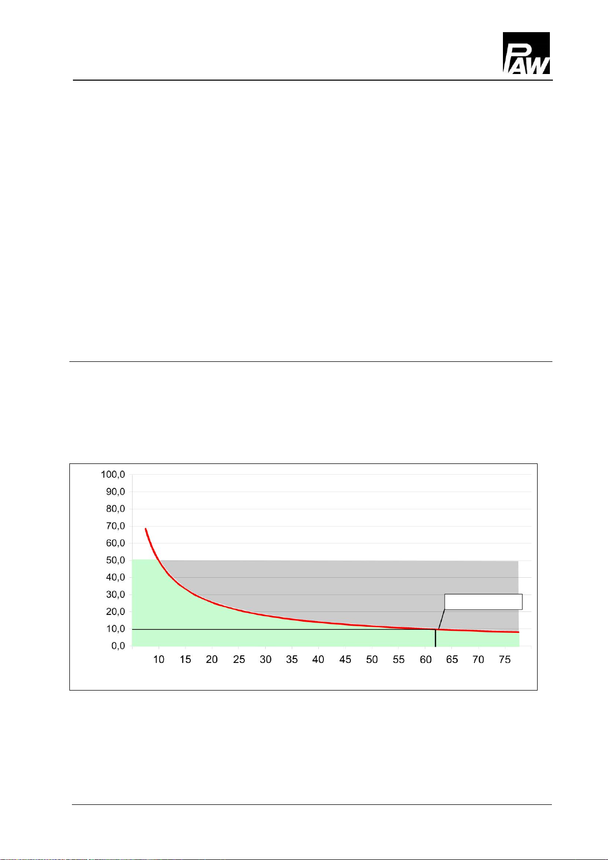
In the diagram below you can see whether the check valves integrated in the station are
sufficient. If the check valves are not sufficient, you need to install additional components to
prevent gravity circulation. You can mount components such as syphons ("heat traps"), 2-way
valves (zone valves) or additional check valves.
Example:
The station comprises two check valves (2 x 200 mm wc = 400 mm wc).
You use a mixture of water and 40% of propylene glycol as a solar fluid.
The installation height between the collector and the storage tank is 10 m.
Installation height in m
Temperature difference storage tank/collector in K
Result:
The check valves prevent gravity circulation up to a temperature difference of about 62 K. If the
temperature difference between the collector and the tank is larger, the difference in density of
the solar fluid will be so large, that the check valves are pushed open.
Circulation
Solar fluid
8 Function of the check valves [Expert]
2017/05 99609x4x5-mub-en – V05 29
Page 30

8 Function of the check valves [Expert]
Do you need to know it exactly?
The density of the solar fluid decreases with rising temperature. In high installations with large
temperature differences, the difference in density will cause gravity circulation. This circulation
can cool down the storage tank.
Calculation example: Δp = Δρ * g * h
collector temperature: 5 °C density solar fluid ρ1 = 1042 kg/m³
tank temperature: 67 °C density solar fluid ρ2 = 1002.5 kg/m³
Δρ = ρ1 - ρ2 = 39,5 kg/m³
g = 9,81 m/s²
Installation height h = 10 m
Δp = 3875 Pa = 395 mm wc
The two check valves in the station (2 x 200 mm wc) are sufficient for an installation height of
10 m and a temperature difference between the collector and the tank of up to 62 K.
30 99609x4x5-mub-en – V05 2017/05
Page 31
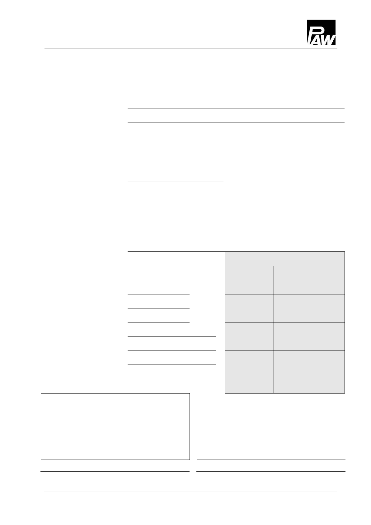
9 Commissioning report
Installation operator
Location of installation
Collectors
(number / type)
Collector surface
m²
Installation height
m
(Difference in height between
station and collector field)
Pipes
⌀ = mm
l =
m
Venting (collector field)
Not existent
Vented
Manual vent valve
Automatic deaerator
Airstop (station)
Vented
Solar fluid (type)
% glycol
Antifreeze (tested up to):
°C
Se ri a l nu mb er s
Flow rate l/m
Station
Pump (type)
Flow rate sensor
System pressure
mbars
Temperature
sensor
Expansion tank (type)
Initial pressure
mbars
Controller
Pressure relief valve
Checked
Check valves
Checked
Software version
Plumbing company
Date, signature
9 Commissioning report
2017/05 99609x4x5-mub-en – V05 31
Page 32

PAW GmbH & Co. KG
Böcklerstraße 11
D-31789 Hameln, Germany
www.paw.eu
Phone: +49 (0) 5151 9856 - 0
Fax: +49 (0) 5151 9856 - 98
32 99609x4x5-mub-en – V05 2017/05
 Loading...