


Pavone Sistemi
pesatura elettronica industriale
Rev. 201301
TECHNICAL MANUAL
MC 353 Flow Rate Controller for belt weigher
Software version 1.9
Pag. 2
MC 353 software 1.9
ENG
SYMBOLS
Following are the symbols used throughout the manual to call reader’s attention:
Further details.
Warning! Electric shock risk
Warning! This operation shall be carried out by qualified staff.
Pay special attention to the following points.
WARNINGS
This manual provides texts and pictures to inform the operator about all prescriptions and criteria necessary for installing and using this instrument.
The equipment shall be installed only by qualified personnel that must have read this manual. With
the expression “qualified personnel” is meant the personnel that has been trained and thus expressly
authorised to carry out the installation by the person in charge for the system safety.
Power the instrument with a voltage value within the limits specified in the features.
The user must make sure that the installation is carried out in compliance with the relevant rules in force.
Please contact the nearest Assistance Centre for every fault you find. Any attempt of disassembly or
change that has not been previously authorised will null and void the warranty and will release the
Manufacturer from any responsibility.
The purchased instrument has been designed and produced to be used in the weighing and metering
processes thus any improper use will release the Manufacturer from any responsibility.

Pag. 3
MC 353 software 1.9
ENG
Table of conTenTs
SYMBOLS ..................................................................................................... 2
WARNINGS .................................................................................................. 2
CE DECLARATION OF CONFORMITY - ............................................................ 5
1 - INTRODUCTION ....................................................................................... 6
1.1 - OTHER FUNCTIONS OF MC353 ............................................................. 8
1.2 - TECHNICAL FEATURES ........................................................................... 9
2 - MC353 INSTALLATION ............................................................................ 12
2.1 - INSTALLATION WARNINGS AND INDICATIONS .................................... 12
2.2 - INSTRUCTIONS FOR A CORRECT INSTALLATION ................................... 13
2.3 - ELECTRIC CONNECTIONS ................................................................... 14
3 - MC353 STRUCTURE AND PARAMETERS ................................................... 25
3.1 - PARAMETERING GENERAL FEATURES .................................................... 25
3.2 - MC353 DISPLAYS ................................................................................ 27
3.3 - SET-UP MENU LEVELS ........................................................................... 31
3.4 - PARAMETERS TABLES ............................................................................ 33
3.5 - LIST OF PARAMETERS TO BE SET ........................................................... 36
3.6 - LIST OF PARAMETERS PRIOR TO COMMISSIONING ............................... 42
4 - INSTRUMENT PROCEDURE ...................................................................... 45
4.1 - INSTRUMENT COMMISSIONING PROCEDURE ...................................... 45
4.2 - IN-OUT TEST PROCEDURE .................................................................... 46
4.3 - SIMULATION PROCEDURE .................................................................... 46
4.4 - MACHINE TEST PROCEDURE ................................................................ 47
5 - SYSTEM CALIBRATION ............................................................................ 48
5.1 - BELT HOMING DYNAMIC PROCEDURE ................................................. 48
5.2 - BELT CALIBRATION DYNAMIC PROCEDURE ........................................... 49
5.3 - ZERO STATIC CALIBRATION AND WITH SAMPLE WEIGHT ...................... 50
5.4 - MC353 OPERATION ALARMS ............................................................... 51
6 - ADDITIONAL FUNCTIONS OF MC353 ..................................................... 53
6.1 - DATA LOGGER .................................................................................... 53
6.2 - SAVE AND LOAD SET-UP ...................................................................... 53

Pag. 4
MC 353 software 1.9
ENG
6.2 - FILE LOADING ..................................................................................... 54
6.3 - RECEIPT PRINT ..................................................................................... 55
7 - SERIAL COMMUNICATION AND PROTOCOLS .......................................... 56
7.1 - ASCII COMMUNICATION PROTOCOL .................................................. 56
7.2 - MODBUS COMMUNICATION PROTOCOL ............................................ 61
7.3 - PROFIBUS-DP COMMUNICATION PROTOCOL ....................................... 62
7.4 - SUPERVISION FUNCTIONS .................................................................. 71
7.5 - MASTER / SLAVE COMMUNICATION PROTOCOL .................................. 71
7.6 - REPETITOR TRANSMISSION PROTOCOL ................................................ 72
8 - TROUBLESHOOTING ............................................................................. 73
8.1 - TROUBLESHOOTING ........................................................................... 73
CONFIGURATION AND TEST FORM ............................................................. 76

Pag. 5
MC 353 software 1.9
ENG
- CE DECLARATION OF CONFORMITY -
· ELECTROMAGNETIC COMPATIBILITY DIRECTIVE
2004/108/EC
· EN61000-6-2, EN61000-6-3, EN61010-1, EN45501 STANDARDS
MANUFACTURER
Electronic commercial denomination: “Metering control electronic instrument”
Model: “MC353”
Protection class: “IP 65”
It is forbidden to start-up the electronic equipment provided with certication before
the electric panel it is going to be integrated or assembled has been declared conforming
with the Directives requirements.
CERTIFICATION
WE, THE UNDERSIGNED OF THIS DOCUMENT, DECLARE UNDER OUR OWN
RESPONSIBILITY THAT THE CONCERNED ELECTRONIC EQUIPMENT IS
CONFORMING WITH THE ITALIAN LAW AND THUS WITH THE ELECTROMAGNETIC
COMPATIBILITY DIRECTIVE 2004/108/EC AS WELL AS THE EN61000-6-2, EN610006-3, EN61010-1, EN45501 STANDARDS.
NAME: POSITION:
ISSUE DATE: SIGNATURE:
ELECTRONIC IDENTIFICATION
Pavone Sistemi S.r.l.
Via Dei Chiosi, 18
20873 Cavenago Brianza (MB) - ITALY
Tel. +39.02.95339165 - Fax +39.02.9501252
pavone@pavonesistemi.it - www.pavonesistemi.it
Donato Di Reda
sole director
03/02/2012
Pag. 6
MC 353 software 1.9
ENG
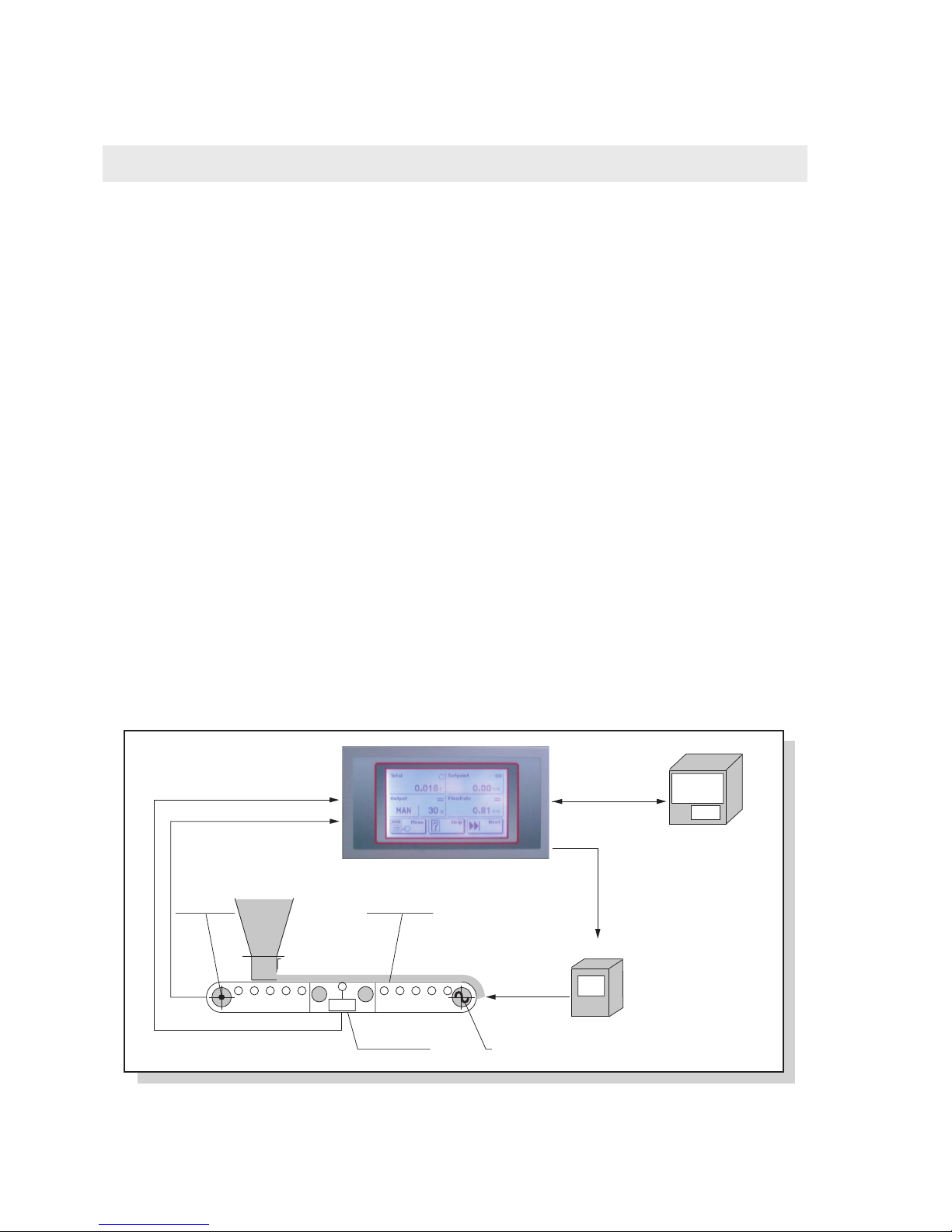
1
Inverter
Encoder
Flow Rate
Motor
Load Cells
MC 353
PLC / PC
MC 353
Inverter
MotorLoad Cells
Weighing Belt
Encoder
PC / PLC
1 - InTRoDUcTIon
The picture shows how the instrument controls the system adjustment ring.
The MC353 can operate as follows according to its set-up:
FLOW RATE TRANSMITTER
The instrument, thanks to the weight (load cells) and the speed (encoder) signal when it receives the run
input, calculates an instantaneous flow rate which is then transmitted externally through a configurable
analogue output (0÷10 V, 0÷5 V, 0÷20 mA, 4÷20 mA).
It is also possible to receive the following outputs:
- Weight totalization output;
- Conveyed weight preset output;
- Conveyed weight set output;
- Serial communication protocol, Ethernet included.
- Generic alarm output;
- Flow rate equal to 0 output;
- Conveyed weight reset input;
- USB device communication port;
- Optional USB HOST port with USB pen drive interface.
FLOW RATE CONTROLLER
The MC 353 control unit is configured with P.I. (instantaneous flow rate) regulator; it processes the weight
and speed variables to get the instantaneous hourly flow rate and the totalized weight. Furthermore it
acts as flow rate self-regulator.

Pag. 7
MC 353 software 1.9
ENG
1
The external supervisor transmits the work set-up (that can be set also through the keyboard) through
the serial communication to the MC353 control unit; the latter, according to the calculated flow rate
value, controls directly (through analogue output) the inverter frequency of the motor where the weighing
system has been installed.
The MC353 control unit has the following features:
- Weight totalization output;
- Conveyed weight total preset and set output;
- Generic alarm output;
- Flow rate out of tolerance alarm output;
- Flow rate output equal to 0;
- Retroaction analogue output (0÷10V;0÷5V, 0÷20 mA; 4÷20 mA);
- Flow rate proportional optional analogue output;
- Optional analogue input for setting-up the flow rate;
- Inputs for the selection of 15 preset set points;
- Conveyed weight reset input;
- Selection of the instrument state from manual to automatic and vice versa by means of the keyboard,
from the instrument rear side through external contact, and by means of serial communication protocol;
- Serial communication protocol, Ethernet included;
- Optional USB HOST port with USB pen drive interface.

Pag. 8
MC 353 software 1.9
ENG
1
1.1 - OTHER FUNCTIONS OF MC353
MASTER-SLAVE OPERATION
This instrument can operate as slave, thus acquiring the flow rate setpoint in continuous duty, through
analogue input (0÷10V / 4÷20mA) or digital input (RS485). The flow rate setpoint is updated according to the current input: the flow rate setpoint is divided and it represents the input scale end (100%).
In case the current setpoint is set to 0, the setpoint will correspond to the input percentage value of the
system maximum flow rate.
The instrument can also operate as master by transmitting the instantaneous flow rate through the optional analogue output or digital transmission (RS485) for the direct connection to instruments in SLAVE
operation.
PARAMETERS THAT CAN BE SET
It is possible to set the operation parameters through the touch screen user interface; all parameters are
organised on 3 levels with independent access criteria.
All parameters that can be set are listed in a table and clearly identified with a numerical code (address).
The parameters reading and writing access is available on the communication port with supervisor
(Rs422 / RS485 / Ethernet, optional), through the ModBus RTU protocol. Furthermore the parameters
reading and setting can be carried out by sharing files in CSV format on the COM2 communication
port (Rs232 or USB) or directly on USB pen drive connected to the USB Host port (optional).
For operation details see the relevant paragraphs.
DATA IMPORT / EXPORT
To facilitate the data set-up and acquisition in a format that can be used with standard informatic systems
the instrument is provided with files transfer functions (TXT or CSV). It features especially a reading/
writing (even partial) of the memory parameters from CSV files and a data logger procedure to acquire
operation parameters.
To customise the instrument it is possible to set the setpoint names, create Help pages and load the
image displayed upon switching-on (BMP file).
If the instrument is provided with a USB Host option, the import and export of the files mentioned above
can occur directly on USB pen drive.

Pag. 9
MC 353 software 1.9
ENG
1
1.2 - TECHNICAL FEATURES
STRUCTURAL FEATURES
Made of aluminium with polycarbonate screen
Protection class: IP 65
Overall dimensions: 196 mm x 105 mm (l x h)
Panel front projection: 5 mm
Built-in panel front.
Drilling template 187 mm x 97 mm (l x h)
Fixing by means of 4 metallic threaded rods
3 mm rubber seal along all perimeter
Stainless steel coating
Overall dimensions: 186 mm x 95 mm (l x h)
Embedding depth: 70 mm (terminal boards included)
5.08 / 7.5 mm pitch screw terminal board
Standard USB connectors (Host / Device)
RJ45 standard Ethernet connector
Front panel
Assembly
Rear panel
Connections
POWER SUPPLY
24 Vdc (± 15 %)
10W
Cat. II
Operation temperature: -10 °C ÷ + 50 °C
(85% humidity without condensate)
Storage temperature: -20 °C ÷ + 60 °C
Power supply
Max. absorption
Installation category
Temperatures
DISPLAY
5.2” LCD (118 mm x 58 mm visual area) (l x h)
Graphic (240x128 pixel)
Monochromatic (b/w) with high contrast
Backlit with white leds, adjustable intensity
4 wires resistive, suitable for use with gloves and buzzer
Display
Touch screen

Pag. 10
MC 353 software 1.9
ENG
1
LOAD CELLS INPUT
2 input channels for load cells. Acquisition at intervals
or simultaneously at low frequency
5 Vdc / 120mA (max. 8 350 Ohm cells in parallel)
Protected against short circuit
0.02 microV min
< 0.01% of the scale end
< 0.0003% of the scale end / °C
24 bit (16.777.216 points)
Up to 600,000 divisions on the flow rate
7.8 mV/V bipolar
From 12.5Hz to 250Hz
Adjustable from 0.2Hz to 50Hz
No. of channels
Cells supply
Input sensitivity
Linearity
Temperature warmup drift
Internal resolution
Weight resolution
Measure field
Acquisition frequency
Digital filter
ANALOGUE I/O
2 opto-isolated analogue outputs (1 optional)
1 analogue input (optional)
Analogue output: 16 bit
Analogue input: 24 bit
Outputs: 0÷5V, 0÷10V, 0÷20mA, 4÷20mA
Input: 0÷5V, 0÷10V, 4÷20mA
Voltage: 10KΩ min, current 300 max
< 0.03% of the Full Scale
< 0.001% of the Full Scale / °C
No. of channels
Resolution
Measure field
Output impedance
Output linearity
Output temperature
warmup drift
1 2-phase incremental encoder input (up-down, A-B).
As an alternative there are 2 pulse-counting inputs
24Vdc (100mA max)
2 KHz max
ENCODER INPUT
No. of channels
Power supply
Acquisition frequency

Pag. 11
MC 353 software 1.9
ENG
1
6 opto-isolated logic outputs (clean contact)
6 opto-isolated logic inputs (PNP)
30 Vdc max / 60 mA each
12 ÷ 24Vdc (external supply)
Up to 4 external modules with 4 in. / 8 out. each
(16 in. / 32 out. in total)
LOGIC I/O
No. of channels
Output power
Input voltage
Additional I/O
3 independent communication ports (not changed-over)
Rs422 / RS485 / Ethernet (option)
Rs232 / RS485 / USB Device (Virtual Com Port)
Rs232 (only transmission for printer or repetitor,
9600 baud).
15 m (Rs232), 1000 m (RS485)
From 1200 m to 115200 bit/sec
TCP/IP, UDP, ARP, ICMP, ModBus/TCP
USB pen drive interface with FAT16/32 file system
management
It can be implemented with an external module
No. of channels
COM1 interfaces
COM2 interfaces
COM3 interfaces
Wire length
Baud rates
Ethernet protocols
USB Host (optional)
DP Profibus (optional)
COMMUNICATION PORTS
Micro-controller
Code memory
Data memory
Clock / calendar
RISC 32 bit, 44 MHz
Flash 256K Bytes, it can be set on-board (Rs232, USB)
1088 Kbytes standards, it can be expanded
up to 2113 Kbytes
Integrated with a rechargeable buffer battery
CPU
EN61000-6-2, EN61000-6-3, EN61010-1, EN45501
CONFORMITY WITH STANDARDS
Standards
Pag. 12
MC 353 software 1.9
ENG
2
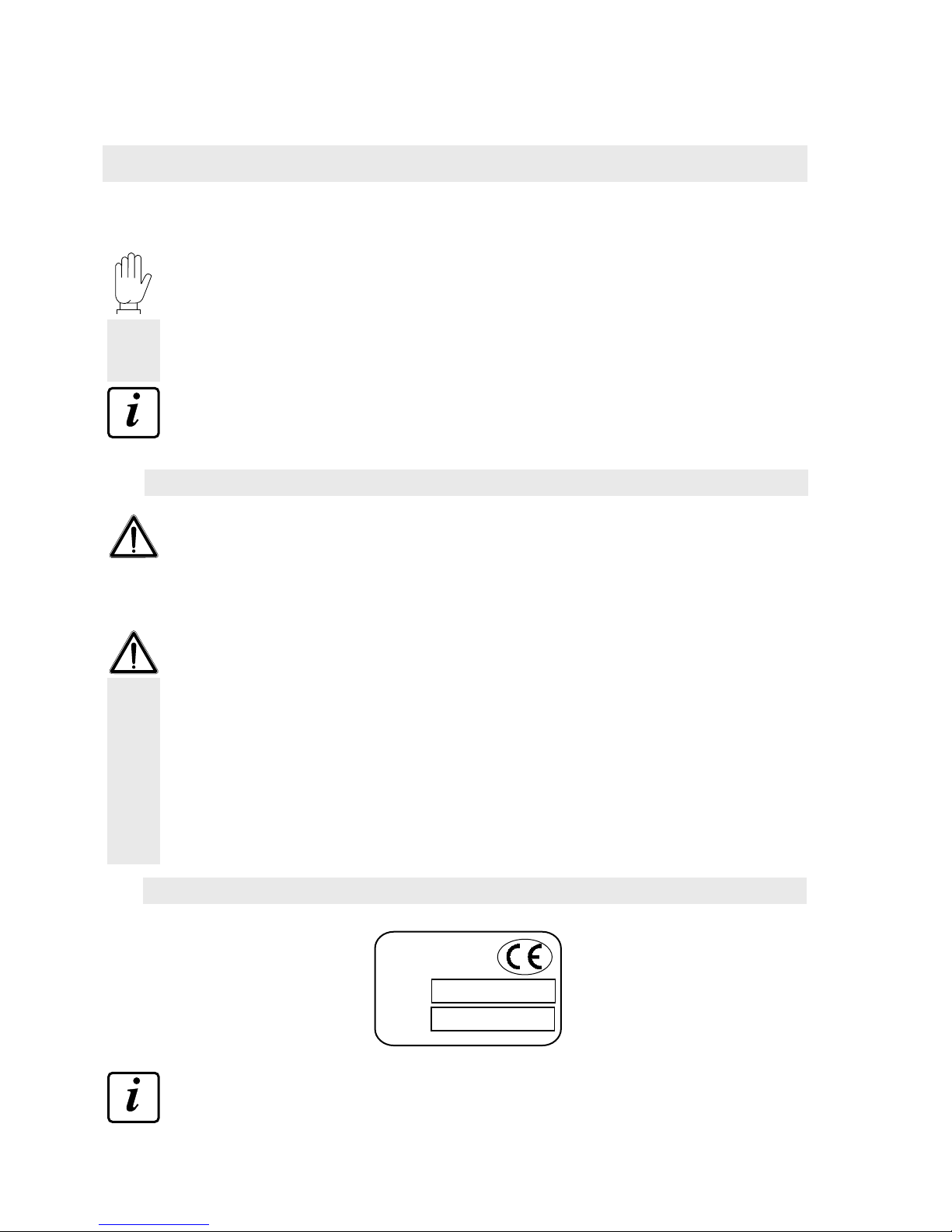
mod.
s.n.
MC 353
2010/0000
2.1 - INSTALLATION WARNINGS AND INDICATIONS
Upon installation it is necessary to arrange after and near the equipment a main switch for an omnipolar
cut-off with contact minimum opening of 3 mm.
For cleaning the instrument make use of a cloth slightly soaked in pure alcohol for both the container
and the display.
During the cleaning the instrument must be OFF.
Environmental pollution level: 2
INSTRUMENT ASSEMBLY
- Only qualified personnel shall carry out the following procedures.
- All connections shall be made with instrument OFF.
The instrument shall be assembled in an opening with a 187 x 97 mm drilling template and shall be
fixed by means of the 4 threaded tie rods supplied together with the instrument.
- Consider that the instrument depth with extractable terminal blocks fitted is of 70 mm, and it is necessary to keep place enough for all connections.
- Do not install the instrument near power equipment (motors, inverters, contactors, etc.) or any equipment
non-conforming with the Electromagnetic Compatibility EC Standards.
- The load cells connection cable shall have a maximum length of 140 mt/mm2.
- The Rs232 serial line shall have a maximum length of 15 meters (EIA RS-232-C Standards).
- All warnings concerning all peripheral devices connections shall be duly followed.
The installation environment can be subject to strong magnetic fields and electric interferences due to
present machinery; it is thus recommended to take all precautions so as to prevent them from affecting
the typical signals of a precision electronic equipment (filters on remote control switches, diodes on 24
Vdc relays, etc.)
INSTRUMENT IDENTIFICATION PLATE
In case of information or indications request concerning the instrument it is important to report such data
along with the programme number and version that are printed on the manual cover and displayed
upon instrument switching-on.
2 - Mc353 InsTallaTIon
Pavone Sistemi s.r.l.

Pag. 13
MC 353 software 1.9
ENG
2
2.2 - INSTRUCTIONS FOR A CORRECT INSTALLATION OF THE LOAD CELLS AND
THE MICROPROCESSOR SYSTEMS
1. Do not carry out weldings with load cells fitted.
2. Use a copper conductor to connect the load upper support plate with the lower one, then connect
both upper plates with the earth line.
3. Use watertight fittings and sheaths to protect the cells wires.
4. Use a watertight connection box and a terminal board with cable clamp to connect the cells in
parallel.
5. All “shielded” cables for signal amplifiers or cells connection extensions shall be inserted alone in
the cable conduit or in a tube as far away as possible from the power cables.
6. The amplifier or cells cable shall be inserted in the panel from one side or the other and it should be
connected directly to the instrument terminal block without being interrupted by additional terminal
blocks or passing through cable conduits with other wires.
7. Use “RC” filters on the coils of remote control switches and the solenoid valves controlled by the
micro-processor.
8. In case of condensate inside the equipment it is recommended to always keep them powered.
9. The electric panel installer shall provide all instrument electric protections (fuses, door lock switch,
etc.).
10. It is recommended to connect the housing of the instrument to the protective earth (possibility to use
the set screws of the control unit).
Pag. 14
MC 353 software 1.9
ENG
2
Set OUT
Pre-Set OUT
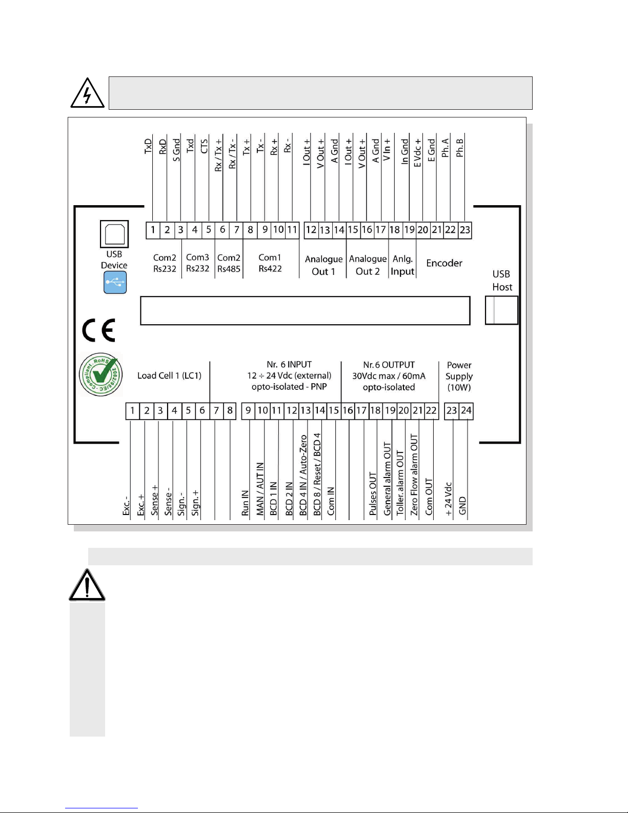
2.3 - ELECTRIC CONNECTIONS
Only qualified personnel shall carry out the procedures described below. All connections shall be
made with instrument OFF.
- The cell cable shall not be inserted together with other cables (for eg. outputs connected with remote
control switches or supply cables), it must be routed in its own path.
- Any cable extension connection shall be carefully shielded, respecting the colour code and using the
cable type supplied by the manufacturer. The extension connections shall be made through welding or
support terminal blocks or connection box supplied as optional.
- The cell cable shall have a number of conductors not higher than those used (4 or 6). In case of a
4-conductors cable connect the reference wires by making a jumper across the relevant poles of the
supply cables.
It is possible to connect up to maximum 8 350 Ohm cells in parallel to the instrument. The cells supply
voltage is of 5 Vdc and is protected against temporary short circuit. The instrument measurement field
foresees the use of load cells with sensitivity from 1 mV/V to 5 mV/V.
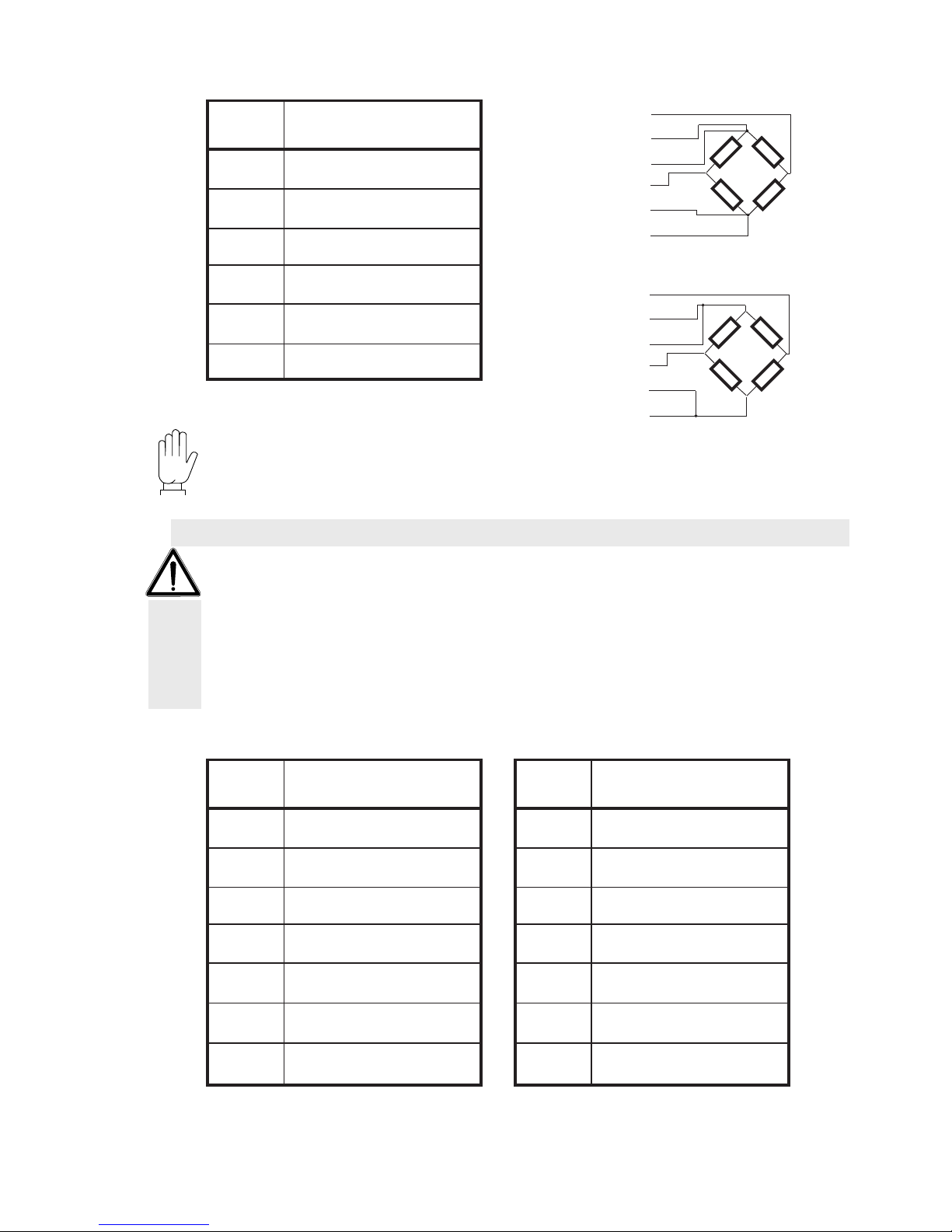
TERMINAL BLOCKS DIAGRAM
LOAD CELL CONNECTION (CONTACTS 1÷6 LOwER TERMINAL BLOCk)
Pag. 15
MC 353 software 1.9
ENG
2
The 6 logic inputs are electrically isolated by the instrument through optoisolators.
The logic inputs connection cables must not be inserted together with power or supply cables and you
have to use a cable as short as possible.
The inputs are active when a voltage of 12 / 24 Vdc is applied (PNP logic).
The 6 logic outputs feature a photorelay (clean contact) with a common contact. The capacity of each
contact is of 60 mA / 30Vdc .
6 WIRES CELL CONNECTION
4 WIRES CELL CONNECTION
NUM.
Lower terminal block
(pitch 5.08 mm)
1
Cell supply -
2
Cell supply +
3
Reference cell +
4
Reference cell -
5
Signal cell -
6
Signal cell +
LOGIC INPUTS AND OUTPUTS (CONTACTS 9÷22 LOwER TERMINAL BLOCk)
Note: to use the 4-wires technique make a jumper across terminal 3 and terminal 2, terminal 4 and
terminal 1.
The cell cable SHIELD must be connected with terminal 1 ( CELL SUPPLY -).
NUM.
Lower terminal block
(pitch 5.08 mm)
9
IN 1 - Run
10
IN 2 - Man / Aut
11
IN 3 - BCD1
12
IN 4 - BCD2
13
IN 5 - BCD4 / Auto 0
14
IN 6 - BCD8 / Reset
15
Input common connector
NUM.
Lower terminal block
(pitch 5.08 mm)
16
OUT 1 - Set
17
OUT 2 - Pre-Set
18
OUT 3 - Tot. pulse
19
OUT 4 - General alarm
20
OUT 5 - Flow rate alarm
21
OUT 6 - Flow rate = 0
22
Output common connector
SIGNAL -
POWER SUPPLY +
REFERENCE +
SIGNAL +
REFERENCE -
POWER SUPPLY
SIGNAL -
POWER SUPPLY +
REFERENCE +
SIGNAL +
REFERENCE -
POWER SUPPLY

Pag. 16
MC 353 software 1.9
ENG
2
IN1 - Run static input. Close this contact to enable instrument begin and maintain programmed operations
(weighing, flow regulation, alarms etc.). Input must be kept closed during dosing; open the contact to
stop operations.
IN2 - Manual selection (open) / automatic (closed). The selection through the keyboard has the priority
over the selection of this input. When a selection that does not correspond to the input state is changed
through the keyboard, to commutate the selection with this input it is necessary to first set the selection
according to what had been done by the keyboard, and then commutate it in the desired position. For
example: with the input set to AUTO, it is possible to commutate it to MAN through the keyboard. To
restore the automatic operation using the input it is necessary to first set the input to MAN and then to
AUTO.
IN3 - Bit 1 setpoint selection with BCD coding. The selection is shown on the display. When all inputs
are open the system keeps the last selected combination (even if you switch off the instrument).
IN4 - Bit 2 setpoint selection with BCD coding. The selection is shown on the display. When all inputs
are open the system keeps the last selected combination (even if you switch off the instrument).
IN5 - The function of this input can be selected: the input (closed by pulses) can control the belt homing
remote procedure. Otherwise you can have the function combined with inputs 3, 4 and 6 for selecting the setpoint with BCD coding. (inp. 5 = bit 4). To start AUTOZERO procedure, close input 1027
(parameter INPUT FUNCTION 5 = “belt reset mode”); the above procedure can be activated only
when 3028 RUN STATUS is STOP. Then, set 3028 RUN STATUS = RUN and keep it that way during
the whole duration of the procedure. The duration of the procedure depends upon the time settings of
parameter 0132 BELT LAP TIME, so please wait until this time elapse. During this period, if there are
any anomalies, will be indicated by the alarm output. If, during AUTOZERO procedure duration, no
alarm is raised, you can safely assume that the procedure has successfully ended. Now you can set
again 3028 RUN STATUS = STOP.
IN6 - The function of this input can be selected: the input (closed by pulses) can control the conveyed
total reset, with receipt print if the printer is suitably set. Otherwise you can have the function combined
with inputs 3, 4 and 5 for selecting the setpoint with BCD coding. (inp. 6 = bit 8 if inp. 5 = bit 4; inp.
6 = bit 4 if inp. 5 is selected to control the belt homing procedure).
NOTE: inputs are activated only if activation time exceeds 500 msec.

Pag. 17
MC 353 software 1.9
ENG
2
OUT1 - Total Set reached. This output is active when the total conveyed product exceeds the set value,
anticipated of the set flying material. If the set value is zero, this output is never excited.
The output is disabled when the total conveyed product is reset.
OUT2 - Total PreSet reached. This output is active when the total conveyed product exceeds the SET
value - PRESET value. If the set value is zero, this output is never excited. The output is disabled when
the total conveyed product exceeds the SET value - PRESET value. If the set value is zero this output is
not excited. The output is disabled when the total conveyed product is reset.
OUT3 - Totalization pulse. This output is excited by pulses (0.5 sec.) each time that the quantity of product that is conveyed is equal to the set value, max. 1 impulse per second (1 Hz)
OUT4 - Functioning alarm. This output is activated when at least one of the scheduled alarms occurs
(except alarm 3). You can program this function. OUT4 is deactivated automatically when function is
one again normal. Output is active during RUN or always according to parameter’s 1030 settings.
OUT 5 - Instantaneous flow rate out of tolerance. During belt’s RUN (only in automatic mode), this output is active if instantaneous flow rate exceeds the set limit. OUT5 is deactivated automatically when
function is one again normal, i.e when flow rate is within tolerance. You can program this function.
OUT6 - Null flow rate alarm (Al 3). During the belt movement this output is active when the null flow
rate alarm (minimum weight or encoder signal missing) is triggered according to the conditions defined
by the 1022 parameter selections.
Pag. 18
MC 353 software 1.9
ENG
2
TX
RX
GND
The instrument is supplied by the 2-pole terminal block with 7.5 mm pitch.
The supply cable shall be inserted separately from other supply cables featuring a different voltage,
from the load cell, encoder and logic and analogue input/output cables.
INSTRUMENT POwER SUPPLY (CONTACTS 23-24, LOwER TERMINAL BLOCk)
NUM.
Lower terminal block
(pitch 7.5 mm)
23
+ 24Vdc
24
GND
POWER SUPPLY: 24Vdc +/-15%
POWER: 10W
WARNING: when using this connection it is not possible to use an RS485 interface and the USB device
port, shared on the same COM2 communication port.
To make a serial connection use a shielded cable having care to connect to earth the screen to only
one of the two sides. In case the cable has more conductors than those used connect the screen to the
free conductors.
The serial connection cable shall have a maximum length of 15 metres (EIA RS-232-C Standards), if it
is longer it is necessary to use the instrument Rs422 interface.
- The cable shall not be inserted together with other cables (for eg. outputs connected with remote control
switches or supply cables), it must be possibly routed in its own path.
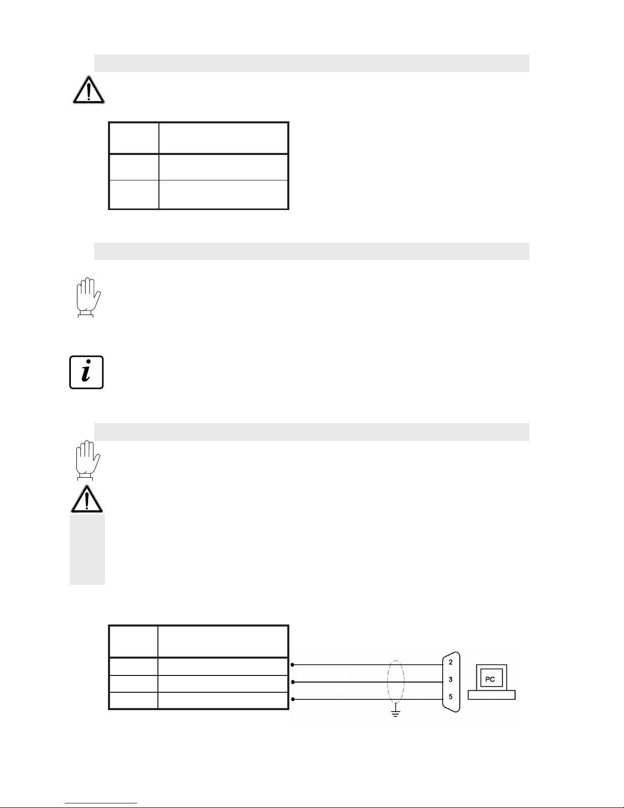
The PC used for the connection shall be compliant with the EN 60950 Standard.
Following is the drawing of the connection with 9-pole PC connector:
COM2 - RS232 SERIAL PORT (CONTACTS 1÷3, UPPER TERMINAL BLOCk)
NUM.
Upper terminal block
(pitch 5.08 mm)
1
2
3
Data transmission
Data reception
Signal mass
WARNING: when using this connection it is not possible to use an RS485 and RS232 interface, shared
on the same COM2 communication port.
Use this communication port to interface directly with a PC or through a USB port.
For the connection use a USB standard cable.
To connect the instrument through the USB device port it is necessary to install on the PC the suitable
driver for the used operative system. Follow specific instructions for the installation.
COM2 - USB DEVICE PORT (REAR USB FEMALE CONNECTOR)
- Specification 2.0 compliant; full-speed 12Mbps -
Note: verify that GND (pin 24) is grounded
Pag. 19
MC 353 software 1.9
ENG
2
MASTER
RS485
TX+ / RX+
TX+ / RX+
TX- / RX-
TX- / RX-
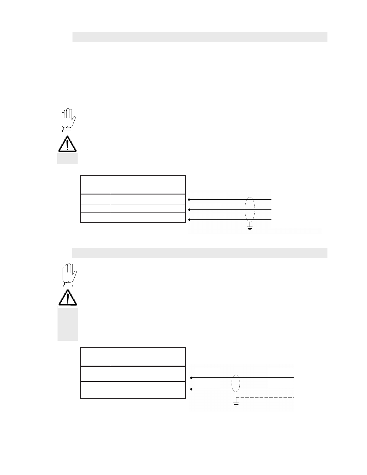
COM3 - RS232 SERIAL PORT (CONTACTS 3÷6, UPPER TERMINAL BLOCk)
NUM.
Upper terminal block
(pitch 5.08 mm)
4
TX
5
cts
3
GND
Data transmission
cts
Signal mass
This communication port is only provided with data transmission functions with fixed communication
parameters. The units that can be connected are a repetition printer or display that shall feature an
RS232 serial interface.
Speed: 9600 bps
Word length: 8 bit.
Start bit: 1 bit. Parity bip: 0 bit. Stop bit: 1 bit.
Handshaking: DTR protocol.
Refer to the printer or repetitor manual to select the communication parameters according to the
transmission.
To make a serial connection use a shielded cable having care to connect to earth the screen to only
one of the two sides. In case the cable has more conductors than those used connect the screen to the
free conductors.
The serial connection cable length shall not exceed 15 meters (EIA RS-232-C Standards).
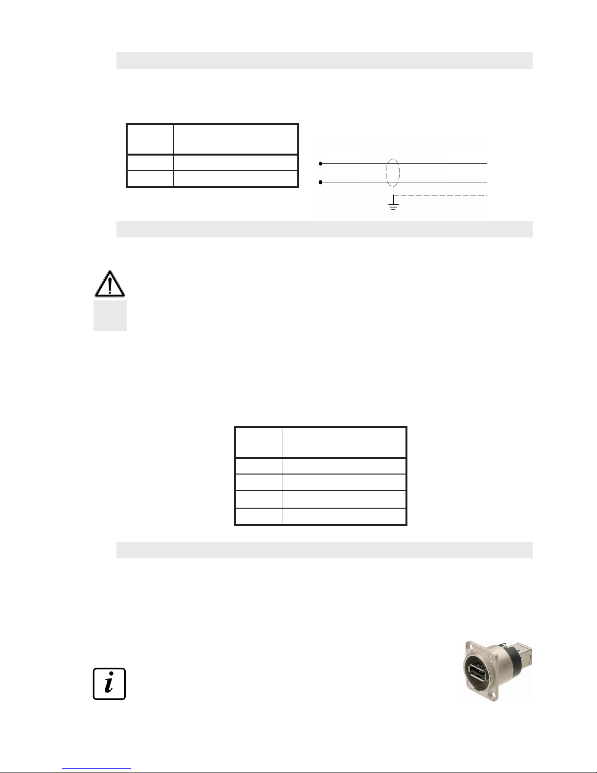
PRINTER -
REPETITOR
COM2 - RS485 SERIAL PORT (CONTACTS 6-7, UPPER TERMINAL BLOCk)
WARNING: when using this connection it is not possible to use an RS232 interface and the USB communication device port, shared on the same COM2 communication port.
Through the RS485 serial interface it is possible to carry out serial connections for long distances.
This type of connection allows to connect more units to one MASTER using one single serial line. The
maximum number of connected units is 32.
The serial connection cable type shall be suitable for RS485 serial communications with 1 twisted pair
and the relevant shielding.
- The cable shall not be inserted together with other cables (for eg. outputs connected with remote control
switches or supply cables), it must be possibly routed in its own path.
Set the terminal line resistors as specified in the following paragraph.
NUM.
Upper terminal block
(pitch 5.08 mm)
6
7
TX- / RX-
TX+ / RX+
Pag. 20
MC 353 software 1.9
ENG
8
9
TXD-
TXD+
10
RXD+
11
RXD-
TXD+
TXD-
RXD-
RXD+
TXD+
TXD-
RXD-
RXD+
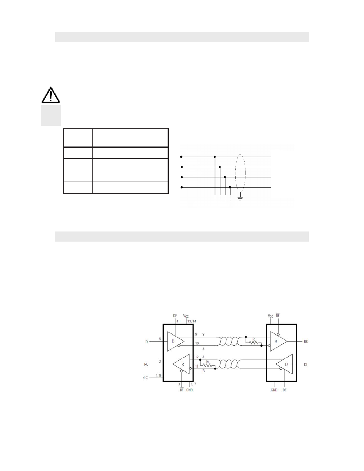
MASTER RS422
2
Through the RS422/RS485 serial interface it is possible to carry out serial connections for long distances.
This type of connection allows also to connect more instruments to one MASTER unit (personal computer,
PLC, etc.), using only one serial line and thus just one MASTER serial port.
The maximum number of connected instruments is 32. Obviously also the master unit shall be equipped
with an RS485 or RS422 serial interface, otherwise it can be supplied as optional.
The serial connection cable type shall be suitable for serial communication with 2 conductor twisted
pairs for RS422, or 1 twisted pair for RS485 and the relevant shielding.
- The cable shall not be inserted together with other cables (for eg. outputs connected with remote control
switches or supply cables), it must be possibly routed in its own path.
Set the terminal line resistors as specified in the following paragraph.
NUM.
Upper terminal block
(pitch 5.08 mm)
Other instrument
For the RS485 connection connect in parallel TXD + with RXD+ and TXD- with RXD-.
COM1 - RS422/485 SERIAL PORT (CONTACTS 8÷11, UPPER TERMINAL BLOCk)
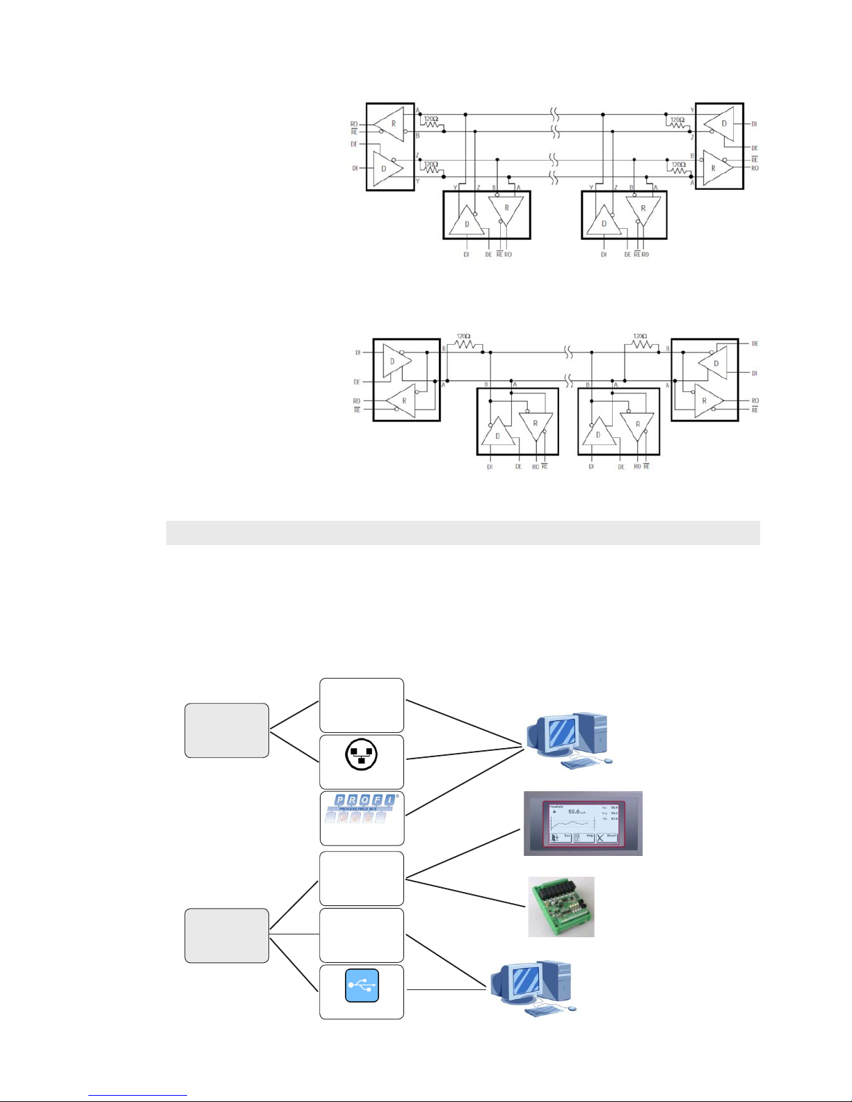
TERMINAL RESISTORS RS485 AND RS422
Data bus transmission on RS485 / RS422 connection is differential type, i.e. signal is the result of
tension difference between the 2 wires composing the bus.RS485 / RS422 transmitters provide an
output (under load) of ±2-3 V between output A and B; receivers recognize output levels up to ±200
mV as a valid signal.
This technique provides excellent disturb immunity even with long cable runs.
To minimize reflections, transmitter must have the possibility to insert the polarizing resistance while first
and last network line element should be equipped with a terminal line resistor, connected inparallel to
the line.
Typically, terminal line resistors must have resistance values between 120 and 560 ohm.
In case of connections with double pairs RS422 and two nodes,
resistances should be near the further receiver while value can be
low up to 120 Ohm (see figure)
Pag. 21
MC 353 software 1.9
ENG
COM 1
Rs422 /
RS485
RS485
RS232
USB device
COM 2
Ethernet
Profibus
2
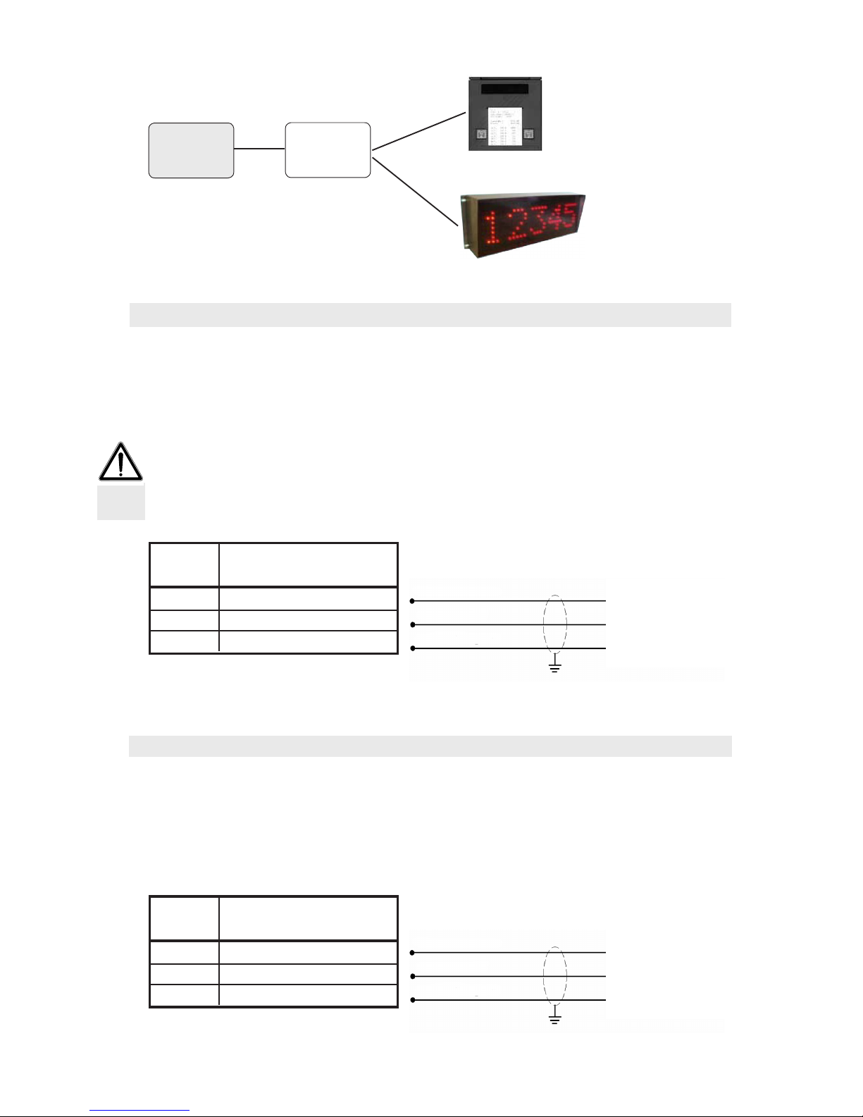
COMMUNICATION PORTS SUMMARY
The instrument is equipped with three independent communication ports: COM1, COM2, COM3.
COM1 has 2 possible interfaces (that can be used alternatively): RS422/RS485, Ethernet or Profibus
(optional).
COM2 has 3 interfaces (that can be used alternatively): RS232, USB device, RS485.
COM3 has an RS232 interface with only transmission functions and CTS management.
Following is a diagram with all possible connections:
Supervision
PC / PLC
service PC:
- programming
- operation display
- firmware update
Additional I/O
module
(optional)
MC353
MASTER / SLAVE
In case of connections with double pairs RS422 and more nodes, same 120 Ohm value is indicated
at the figure, but this is valid
for very long lines (hundreds
of meter). If line is considerably shorter, resistance
value must raise because
impendence at 120 Ohm
would be very low, 60 Ohm
(not counting the receivers
load). It would be better to
use resistances in the ~250
Ohm range.
Same considerations apply
to the RS485 connection.
Use 250 Ohm resistances for
lines not very long.
(optional)
(optional)
Pag. 22
MC 353 software 1.9
ENG
2
RS232
COM 3
13
+ Volt
14
GND
12
+ mA
16
+ Volt
17
GND
15
+ mA
Printer from panel
Repetitor display
MAIN ANALOGUE OUTPUT (CONTACTS 12÷14, UPPER TERMINAL BLOCk)
The instrument is provided with a current and a voltage analogue output.
Features:
- Voltage analogue output: range from 0 to 10 Volts or from 0 to 5 Volts, minimum load 10KOhm;
- Current analogue output: range from 0 to 20 mA or from 4 to 20 mA. The maximum load is 300Ohm.
For the connection use a shielded cable having care to connect to earth the screen to only one of the
two sides.
The analogue transmission is particularly sensitive to the electromagnetic interferences and thus we
recommend that the cables are as short as possible and that they follow an independent path.
NUM.
Upper terminal block
(pitch 5.08 mm)
+ VOLTAGE
- COMMON
+ CURRENT
OPTIONAL ANALOGUE OUTPUT (CONTACTS 15÷17, UPPER TERMINAL BLOCk)
The instrument can have a second optional analogue output with the same features of the serial one.
Features:
- Voltage analogue output: range from 0 to 10 Volts or from 0 to 5 Volts, minimum load 10 KOhm;
- Current analogue output: range from 0 to 20 mA or from 4 to 20 mA. The maximum load is 300 Ohm.
NUM.
Upper terminal block
(pitch 5.08 mm)
+ VOLTAGE
- COMMON
+ CURRENT
Pag. 23
MC 353 software 1.9
ENG
2
19
GND
18
+ Volt / + mA
-
+
-
+
21
20
23
22
OPTIONAL ANALOGUE INPUT (CONTACTS 18÷-19, UPPER TERMINAL BLOCk)
It is possible to have an analogue input as optional with measurement field 0÷5V, 0÷10V, 0÷20mA,
or 4÷20 mA. The measurement field shall be chosen during the order stage and can not be selected
by the instrument.
The ADC has a 24 bit resolution.
NUM.
Upper terminal block
(pitch 5.08 mm)
ENCODER INPUT (CONTACTS 20÷23, UPPER TERMINAL BLOCk)
Connection for 2-phase encoder with 24 Vdc power supply.
- The encoder cable shall not be inserted together with other cables (for eg. outputs connected with
remote control switches or supply cables), it must be routed in its own path.
- Any cable extension connection shall be carefully shielded, respecting the colour code and using the
cable type supplied by the manufacturer. The extension connections shall be made through welding or
support terminal blocks.
The maximum frequency of the encoder signals acquisition is of 2 KHz. Fit the encoder so as to avoid
exceeding such work frequency. Example: if the encoder resolution is of 10000 pulses / rev. the rotation
speed shall not exceed 12 rpm.
The encoder acquisition is of the up-down type (counting in both rotation senses). For this reason both
phase cables (A and B). The rotation sense is automatically detected by the instrument.
NUM.
Upper terminal block
(pitch 5.08 mm)
GND suppl. encoder
24 Vdc suppl. encoder
Encoder phase B
Encoder phase A
This optional interface allows to directly connect a USB pen drive for reading and writing files according
to the FAT16/32 standard FAT files system.
Features:
USB connections: Mass storage device
Communication modes: USB specification 1.1 and 2.0
Pen drive maximum capacity: 2 GB
To facilitate the insertion of the USB pen drive it is possible to transfer to panel
front side the connector (USB “A” female type) through the special accessory upon
request (see side picture).
USB OTG OPTION
Pag. 24
MC 353 software 1.9
ENG
2
ETHERNET OPTION
Features:
Transmission speed 10 Mbps
Network Compatible with networks 10/100/1000 Base-T
Ethernet protocols TCP/IP, UDP, ARP, ICMP, ModBus/TCP
Communication mode TCP server
LED indicators (2) Presence of Ethernet line and communication / diagnosis
Buffer dimension 256 byte
Connection Timeout Min 30 seconds - Max 90 seconds
Link Timeout (disconnected cable) 30 seconds
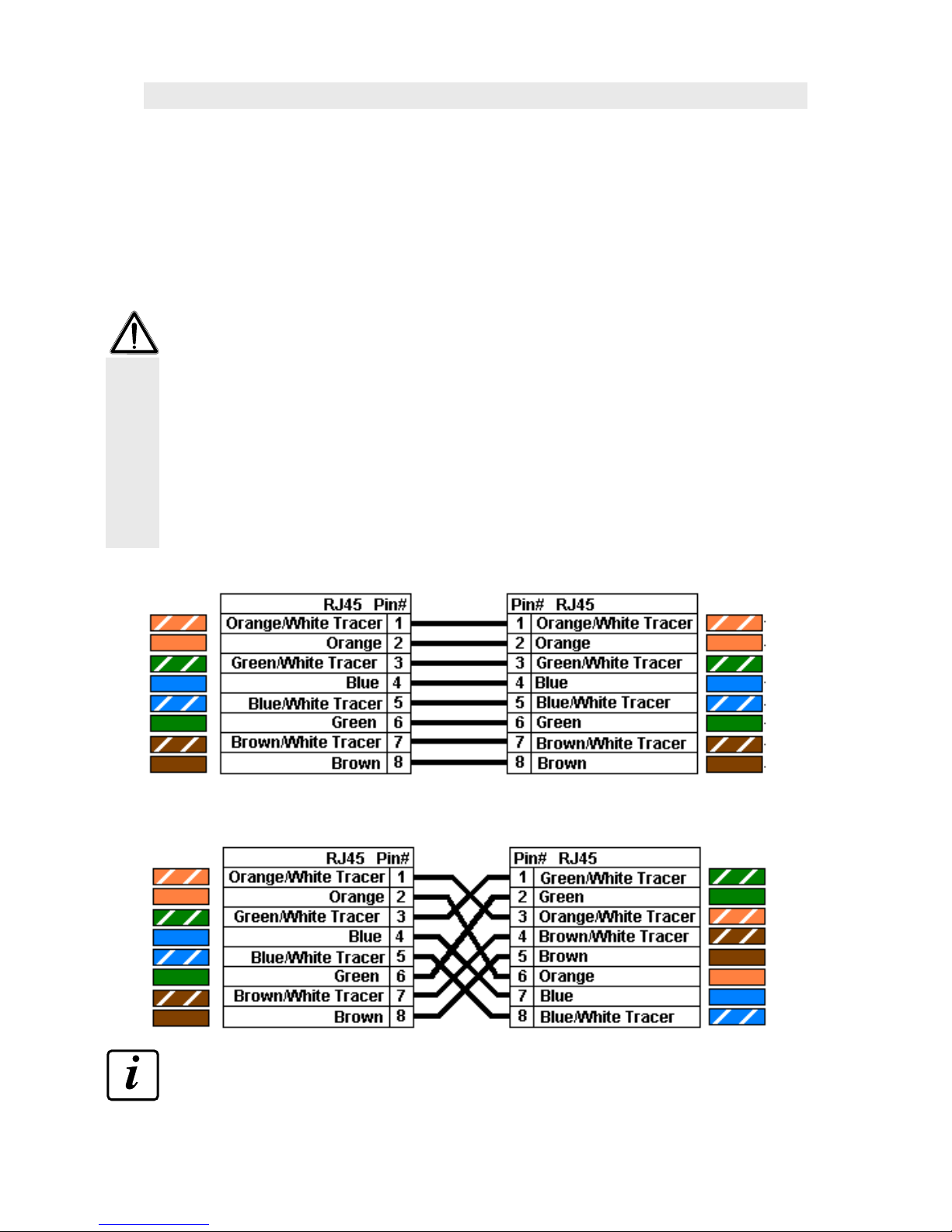
- The RJ45 ethernet connection cable has a variable length which depends on the cable type. One Cat5
standard shielded cable can have a maximum length of nearly 180 m.
- It is possible to connect the ethernet communication port directly to the PC without passing through
other network devices (routers, switches, hubs, lan-bridges or other), but it is necessary to use special
RJ45 cables called “crossover”.
- Usually cables are of the “direct” type, and they allow a connection to network devices such as routers or hubs, but not to directly connect the two PCs (even if currently there are network boards with
auto-sensing technology that recognise the cable and the connection type thus allowing PC-PC direct
connections even without using crossover cables).
- Following are the diagrams of the two mentioned cable types and the relevant connection diagram.
- The cable shall not be inserted together with other cables (for eg. outputs connected with remote control
switches or supply cables), it must be possibly routed in its own path.
“Direct” cable diagram
“Crossed” cable diagram
WARNING: for the Ethernet interface configuration please refer to the specific manual.

Pag. 25
MC 353 software 1.9
ENG
3
3 - Mc353 sTRUcTURe anD PaRaMeTeRs
ELECTRONIC SwITCHING-ON
Upon switching-on the display temporarily shows an introduction window, with the indication of the
firmware code and version.
Press set-up during this stage to enter the set-up menu.
Firmware code
Key to enter the set-up menu
It is important to report the firmware code in case of information or indications request regarding the
instrument.
DATA GENERAL DISPLAY
The general display window is divided into 4
sections, each one dedicated to one measure or
one parameter.
The window is divided into 2 pages that can be
viewed with the Next and Prev keys.
This is the standard display during the operation
and in stop conditions. According to the case
press one section to enter one dedicated window
with further details.
In the lower side are 3 “touch” keys with a contextual function.
It changes the base window
display from page 1 to page 2.
It changes the base window
display from page 2 to page 1.
It displays the contextual Help
window that can be set.
This allows you to enter the user
menu for setting the parameters
3.1 - PARAMETERING GENERAL FEATURES

Pag. 26
MC 353 software 1.9
ENG
3
Conferma il valore corrente e lo
memorizza.
Abbandona la programmazione
scartando la modifica.
Visualizza la schermata di Help
contestuale, programmabile.
CONTROL AND PARAMETERS MENU MODE
The menu widows are divided into 2 types: control menu and parameter menu according to the context
and the data set-up menu structure.
One control menu can be made up of 1 to 9 items
per window. In case the controls are more than 9
they are subdivided into more pages.
Press the key with the control description to activate it.
One parameter menu can be made up of 1 to 9
items per window. In case the controls are more
than 9 they are subdivided into more pages.
Press the key with the parameter description to get
access to its set-up.
Control description
Parameter with relative unit
of measurement and value
It allows you to enter the next
page of the menu (items > 9).
It allows to quit the menu and
go back to the upper level of
the general window.
PARAMETERS SET-UP MODE
The parameters set-up procedures are divided into 2 types: set-up of numerical parameters and selection
of parameters with preset value.
Current value
Composition keys
Current selection
Selection keys

Pag. 27
MC 353 software 1.9
ENG
3
3.2 - MC353 DISPLAYS
SECTION 1: TOTAL
In the main window press the “Total” section to enter the detailed window concerning the instantaneous
hourly flow rate, where additional information are reported.
The graphic bar and the percentage value on the
right side indicate that the conveyed total product
proportion according to the set total setpoint.
Totalization pulse state (it becomes dark when active).
Total reset, with confirmation request
Conveyed total weight setpoint. When
the total reaches this value the relevant
output is activated.
When less than this value is missing to
reach the setpoint, the relevant output
is activated.
Output activation advance with respect
with the setpoint value
Set
Preset
Queue
If the total setpoint management function is not selected press any section of the main window to directly
reset the total, with confirmation request.
SECTION 2: SET POINT
In the main window press the section to access the detailed windows of the flow rate setpoint, where
you enter also the setpoint values set-up.
Number of selected setpoint.
Value of the active setpoint
possibly modified
by the master unit.
Name of the selected setpoint that can be set
by the user.
The graphic bar and the percentage value on the
right side indicate the proportion of the active setpoint
value with respect to the scale end, or to the setpoint
whole value in case the setpoint change input is
activated by the master.

Pag. 28
MC 353 software 1.9
ENG
3
With this you enter the 15
setpoint set-up menu. Upon
conrmation of the setpoint
values you enter the relevant
manual output value.
Flow rate setpoint value that can be
selected.
Theoretic adjustment percentage manual output linked with the
setpoint.
Setpoint
Output
manual
TECHNICAL NOTE: MANUAL OUTPUT LINKED WITH THE SETPOINT
To each setpoint is associated one adjustment manual output percentage.
- When one setpoint value is set or changed, an associated manual output value is suggested which is
calculated proportionally according to the scale end value; it is then possible to change the suggested
value.
- When you select a new setpoint the associated manual output value is taken as adjustment starting
value (both AUTO and MAN).
- When during the operation you change from AUTO to MAN, the output current value is saved in the
manual output parameter associated with the Setpoint.
SECTION 3: MAN / AUTO OUTPUT
The output section can indicate whether the value calculated by the MC 353 in automatic mode for the
adjustment output, or the value calculated in manual mode by the user.
Output trend (up, down, stable)
Press the AUTO section to change the MAN operation. The current output
is acknowledged in the manual operation.
If the input state is set to AUTO (closed) a confirmation request is required
on the relevant window.
In case of manual operation the section is divided into 2 “touch” areas.
Press left on MAN to change to AUTO, with any confirmation window according to the selection input state.
Press right on the output value to access the value change
function and to keep the manual operation.

Pag. 29
MC 353 software 1.9
ENG
3
In the main window press the section to enter the detailed window concerning the instantaneous hourly
flow rate, where additional information are reported.
Output trend (up, down, stable)
The display shows the current hourly flow rate values,
the minimum, the maximum and the arithmetic mean
of the previous instantaneous hourly flow rate values
represented in the graphic.
TECHNICAL NOTE: HOURLY FLOW RATE GRAPHIC REPRESENTATION
The graphic shows up to 150 values of hourly flow rate calculated during the operation according to
the set sampling time. If the sampling time is of 3 sec. the graphic represents up to 7 minutes and a half
of operation. When the graphic is completed the last third (50 values) are drawn at the beginning and
the representation goes on from that moment.
The Max, Min and mean values refer to the values on the graphic.
The central reference line refers to the current flow rate setpoint, whereas the hatched lines above and
under the central one represent the setpoint tolerance.
It quits the window and displays
the main screen.
It draws the graphic and recalculates
the data on the last 50 values.
It displays the contextual Help
window that can be set.
SECTION 4: HOURLY FLOw RATE
SECTION 5: CORRECTION FACTORS
This section displays the correction factors applied to calculate the hourly
flow rate and the following data. Factor K is determined with the belt
calibration procedure.
Another KK correction coefficient can be set by the serial line through the
described protocols. Such KK coefficient is applied additionally to the K
general coefficient.
SECTION 6: CURRENT wEIGHT
This section displays the detected current weight. During the run the display
shows also the weight trend (up, down or stable).
In case of non-connected load cells or faults in the connection cables, the
writing NO CONN (not connected) appears instead of the measure.

Pag. 30
MC 353 software 1.9
ENG
3
SECTION 7: STATE AND TIMER
This display shows a message that indicates the instrument operation state, and one timer (hours:minutes:seconds) relevant to the run time, that is
reset upon run start. The state message in the general window indicates
the STOP and RUN conditions whereas in other procedures it can assume
the following data:
belt calibration procedure in progress
System test procedure in progress
Belt homing procedure (preparation)
Belt homing procedure (execution)
Operation simulation procedure in progress
Belt cal.
System test
Reset waiting
Reset in progress
Simulation
SECTION 8: ENCODER SPEED AND PULSES
This section displays the belt instantaneous speed value (in mm/min) and
calculated at each sampling period according to the pulses acquired by the
encoder and the belt sizing parameters. Pulse value refers to the counting
during the sampling period.
During the operation the display shows also the speed trend with respect
to the previous values (up, down, stable).

Pag. 31
MC 353 software 1.9
ENG
3
3.3 - SET-UP MENU LEVELS
The parameters that can be set are organised in 3 different levels: User, Technician and set-up.
For each level it is possible to enable one access password for the menu.
A change of the could parameters can jeopardise the machine operation and thus we recommend it to
be carried out only by qualified personnel and anyway after having read the manual.
USER MENU - ( MENU )
It contains the functions and parameters that can be usually modified by the operator according to the
working needs.
It is possible to enter the user menu by pressing the relevant key in the base general window.
This allows you to enter the user
menu for parameters’s setting.
During the run with this procedure you enter directly the adjustment parameters and not the user menu
that is not available with running instrument.
TECHNICAL MENU - ( MENU -> TECHNICAL MENU )
It contains the test functions and the set-up relevant to the machine type and the operation mode; usually
it must be used in the starting stage (recommended for qualified personnel).
It will only be possible to enter the User Menu and select the suitable TECHNICAL MENU control only
with stopped metering.
SET-UP MENU - (ACCESS RECOMMENDED ONLY FOR qUALIFIED PERSONNEL)
It contains the instrument set-up functions/parameters, the modification of the parameters is usually
reserved to the supplier.
The access to the set-up occurs upon switching-on
when the introduction window is displayed.
Press set-up to access the relevant menu.

Pag. 32
MC 353 software 1.9
ENG
3
PARAMETERS SET-UP MENU - SET-UP LEVELS PROTECTION
It is possible to associate to each level a protection password that can be set through the technical menu,
and it will be required to enter the relevant menu.
If you set 0 as password the access to the menu is free, thus the password request is disabled.
From the TECHNICAL MENU select LEVEL PROTECTION; from here it is possible to determine the Touch
Screen protection level and any set-up of the 3 passwords (4-digit passwords).
The block level can be selected among the 3 following modes:
FREE
LOW LEVEL
HIGH LEVEL
Free access to the sections of the general window and to the user
menu without password.
Free access to the general window sections, but a password is required
(if set) to enter the user menu.
Denied access to the general window sections and a password is required (if set) to enter the user menu. Free access to the general window
sections and to the user menu without password.

Pag. 33
MC 353 software 1.9
ENG
3
1001
1002
1003
1004
1005
1041
1042
1043
1044
1045
1061
1062
1063
1064
3015
1021
1022
1023
1024
1025
1026
1027
1028
1029
1030
USER MENU
REGULATION PAR.
I/O SELECTION
OPERATION TIMERS
VARIABLE FILTERS
GRAND TOTAL
DISPLAY SETTING
TECHNICAL MENU
REGULATION PAR.
I/O SELECTION
OPERATION TIMERS
VARIABLE FILTER
GRAND TOTAL
DISPLAY SETTINGS
TECHNICAL MENU
Sampling Time
Proport. Const.
Integral Const.
Dead Band
Flowrate Limit
Tot. Pulse Value
Al. Min. Weight
Alarm Out Logic
Toler. Out Logic
Al. Regulation
Al. Encoder
Input 5 Function
Input 6 Function
Tolerance alarm
Always alarm
Stop Delay
Weight Timeout
Regulat. Delay
Flow Limit Delay
Limit. Init. Delay
Flowrate Filter
Weight Filter
Minimun Weight
Min. Analog Out
Grand Total
(Specific Procedure)
(Go to Tecnical Menu)
3.4 - PARAMETERS TABLES

Pag. 34
MC 353 software 1.9
ENG
3
0101
0102
0103
0104
0105
0106
0107
0108
0109
0111
0113
0121
0122
0123
0124
0152
0154
0155
0156
0157
0158
0159
0160
0161
0162
0163
0164
n/a
n/a
n/a
TECHNICAL MENU
COMM. PORTS
TEST FUNCTION
ACCESS LEVELS
DATE & TIME
SYSTEM CALIBR.
BELT SPECIFICAT.
DATA LOGGER
SYSTEM TEST
COMM. PORTS
COM1 Protocol
COM1 Baud rate
COM1 Frame Sel.
COM2 Protocol
COM2 Baud rate
COM2 Frame Sel.
COM3 Protocol
Comm. Address
Profibus Address
Profinet IP Address
Profinet S. Mask
TEST FUNCTION
I/O TEST
SYS. SIMULATION
1ST. AN. OUT TEST
2ST. AN. OUT TEST
(OPTIONAL)
ACCESS LEVELS
Touch Panel Lock
User’s Password
Technical Passw.
Service PIN
DATE & TIME
Current Date
Current Time
SYSTEM CALIBR.
BELT ZEROING
BELT CALIBR. ADJ.
WEIGHT CALIBR.
DENSITY CALIBRATION
BELT SPECIFICAT.
Max Flow Rate
Load Cells Cap.
Roller Diameter
Pulses / Round
Encoder Phase
Roller Distance
Belt Tilt Degrees
Load Cell. Sensit.
Belt Speed
Total’s Resolut.
Dead Band Unit
Tolerance Unit
SYSTEM TEST
(Specific Procedure)
DATA LOGGER
Data Log Mode
TECHNICAL MENU - PARAMETERS LIST

Pag. 35
MC 353 software 1.9
ENG
3
0011
0012
0013
0014
0015
0016
0017
0018
0019
0020
0021
0022
0023
0024
0026
0028
SYSTEM SETUP
SYSTEM SETUP
SAVE SETUP
LOAD SETUP
FILES LOADING
FACTORY SETUP
SAVE PROFI I/O
LOAD PROFI I/O
SYSTEM SETUP
Operat. Function
Encoder
Total Batch
Input f. Master
2nd Analog Out
3nd Analog Out
Analog Input
USB Host Port
Language
1st An. Out Range
2st An. Out Range
KK Factory select
Density F.S.
Weight Vis.
Weight F.S.
Speed F.S.
SETUP SAVING
(Specific Procedure)
SETUP LOADING
(Specific Procedure)
FILES LOADING
FILE H01.TXT
FILE H02.TXT
FILE H03.TXT
FILE H04.TXT
FILE H05.TXT
FILE H06.TXT
FILE H07.TXT
FILE H08.TXT
FILE H09.TXT
FILE H010.TXT
FILE SPLASH.BMP
FILE SETPOINT.TXT
FILE INEXT.TXT
FACTORY SETUP
SET WEIGHT ZERO
SET WEIGHT 2mV/V
SET D/A OUT1 Volt
SET D/A OUT1 mA
SET D/A OUT2 Volt
SET D/A OUT2 mA
SET ANALOG IN ZERO
SET ANALOG IN 10V
SET-UP MENU - PARAMETERS LIST

Pag. 36
MC 353 software 1.9
ENG
3
0011
0012
0013
0014
0015
0016
0017
0018
0019
0020
0021
0022
0023
0024
0026
0028
0101
0102
0103
0104
0105
0106
0107
0108
0109
0111
0113
0121
0122
0123
0124
0131
0132
0133
0134
0135
0141
0143
0152
0154
0155
0156
0157
0158
0159
0160
0161
0162
0163
0164
0182
Addr. Name Decription Unit Menù
Operat. Function
Encoder
Total Batch
Input f. Master
2nd Analog Out
3th Analog Out
Analog Input
USB Host Port
Language
1st An.Out Range
2nd An. Out Range
Sel. factor KK
FS density
Weight selection
FS Weight
FS Speed
COM1 Protocol
COM1 Baud rate
COM1 Frame Sel.
COM2 Protocol
COM2 Baud rate
COM2 Frame Sel.
COM3 Protocol
Comm. Address
Comm. Profibus
Profinet IP
Profinet Sn.M.
Touch Panel Lock
User Password
Technical Passw.
Service PIN
Operation Mode
Belt Lap Time
Belt Lap Lenght
Tare Weight
Max Remote Tare
K Factor
KK Factor
Max Flow Rate
Load Cells Cap.
Roller Diameter
Pulses / Round
Encoder Phase
Roller Distance
Belt Tilt
Load Cells Sens.
Belt Speed
Total’s Resolution
Dead Band Unit
Tolerance Unit
Effective Max Flow
Operating mode sel. (transmitter/adjuster)
System encoder availability sel. (no/yes)
Totalization function with setpoint check sel. (no/yes)
Capacity setpoint adj. Master input sel. (no/serial/analogue)
Selection of optional analogue output activation ( no / flow rate / density);
Selection of optional 3rd analogue output activation ( no / density);
Additional analogue input availability sel. (no/yes)
USB Host port availability for memory key sel. (no/yes)
Messages language sel.
Main analogue output range sel. (0÷5V/0÷10V/0÷20mA/4÷20mA)
Optional analogue output 2A range sel. (0÷5V/0÷10V/0÷20mA/4÷20mA)
Abilitation selection about KK factor (false/true)
Density full scale
Weigh visualization selection (weigh, weigh/meter)
Weigh full scale for 3rd analogue output (kg or kg/min, to be selected)
Speed full scale for 3rd analogue output
COM1 protocol sel. (none/ModbusRTU/Ascii/Profibus)
COM1 baud rate sel. (1200/2400/4800/9600/19200/38400/57600)
COM1 data frame format sel. (N81/N82/E81/O81/E72/O72/E71)
COM2 protocol sel. (none/monitor/master/slave)
COM2 baud rate sel. (1200/2400/4800/9600/19200/38400/57600)
COM2 data frame format sel. COM2 (N81/N82/E81/O81/E72/O72/E71)
COM3 protocol sel. (none/printer/repeater)
Serial communication address
Profibus communication address
Address mod. Profinet (32 bit, 8 bit for each IP address field)
Address Subnetmask mod. Profinet (32 bit, 8 bit for each IP address field)
Touch panel block level sel. (none/low/high)
User’s programming menu access password
Engineer’s programming menu access password
Setup menu access service password
Belt reset mode sel. (time/length)
Belt complete rotation time for reset procedure
Belt complete rotation length for reset procedure
Belt tare
Max resettable weight value from input or serial
Correction factor for capacity acknowledgement
Additional correction factor for capacity acknowledgement
System sized hourly max. capacity
System load cells total nominal capacity
Diameter of roller encoder is fitted onto
Encoder nominal resolution
Encoder phases acknowledgement system (x1/x2x/x4)
Rollers gap on weighing bridge
Belt inclination in degrees
Load cells average sensitivity
Belt fixed theoretical speed, if the encoder is disabled
Total conveyed weight resolution compared to capacity unit (10x/100x)
Adjustment deadband measurement unit selection (kg/h / %)
Capacity tolerance measurement unit selection (kg/h / %)
Max. hourly flow rate calculated proportionally to test valuesystem test
Level 1 - SYSTEM
Level 2 - TECHNICAL
Logic
Logic
Logic
Select
Logic
Logic
Logic
Select
Select
Select
Select
Select
kg/dm3
Select
kg-kg/m
m/min
Select
Select
Select
Select
Select
Select
Select
Number
Number
Number
Number
Select
Code
Code
Code
Select
sec
cm
kg
kg
Coeff.
Coeff.
kg/h
kg
cm
°
pls/round
Select
cm
mV/V
m/min
Select
Select
Select
kg/h
System
Setup
Comm.
Ports
Access
Level
Test
Belt
Specification
System
Calibr.
3.5 - LIST OF PARAMETERS TO BE SET

Pag. 37
MC 353 software 1.9
ENG
3
1001
1002
1003
1004
1005
1006
1007
1021
1022
1023
1024
1025
1026
1027
1028
1029
1030
1041
1042
1043
1044
1045
1061
1062
1063
1064
2002
2004
2006
2041
2042
2043
2044
2045
2046
2047
2048
2049
2050
2051
2052
2053
2054
2055
2056
2057
2058
2059
2060
2061
2062
2063
2064
2065
2066
Sampling Time
Proport. Constant
Integral Constant
Dead Band
Flowrate Limit
Dead Band %
Flowrate Limit %
Tot. Pulse Value
Alarm Min.Weight
Alarm Out Logic
Toler. Out Logic
Alarm Regulation
Alarm Encoder
Input 5 Function
Input 6 Function
Tolerance Alarm
Always Alarm
Stop Delay
Weight Timeout
Regulation Delay
Flow Limit Delay
Limit Init. Delay
Flowrate Filter
Weight Filter
Minimun Weight
Min. Analog Out
SET
Pre-SET
Flying
Setpoint 1
Manual Out Set 1
Setpoint 2
Manual Out Set 2
Setpoint 3
Manual Out Set 3
Setpoint 4
Manual Out Set 4
Setpoint 5
Manual Out Set 5
Setpoint 6
Manual Out Set 6
Setpoint 7
Manual Out Set 7
Setpoint 8
Manual Out Set 8
Setpoint 9
Manual Out Set 9
Setpoint 10
Manual Out Set 10
Setpoint 11
Manual Out Set 11
Setpoint 12
Manual Out Set 12
Setpoint 13
Manual Out Set 13
Hourly capacity sampling time
Adjustment algorithm proportionality constant
Adjustment algorithm integration constant
Capacity gap around the Set where adjustment does not occur
Capacity Setpoint tolerance
Capacity gap around the Set where adjustment does not occur %
Capacity Setpoint tolerance %
Totalized weight corresponding to output pulse
Min. weight alarm enable sel. (disabled/no capacity/min. weight)
Alarm output operation logic sel. (NA/NC)
Output operation logic sel. outside capacity tolerance (NA/NC)
Adjustment alarm enable sel. (no/yes)
Encoder alarm enable sel. (no/yes)
Logic input No.5 function sel. (Setpoint sel./belt reset)
Logic input No.6 function sel. (Setpoint sel./belt reset)
Selection to activate the out of tolerance alarm (no/yes)
Selection to activate permanently the alarms, even when not in RUN (no/yes)
Run stop delay
Max. time period where weight can be constant
Adjustment enable delay upon run start
Capacity output enable delay outside tolerance limits
Capacity tolerance control delay upon run start
Hourly capacity filter factor
Weight filter factor
Min. detected weight to calculate a hourly capacity
Adjustment min. value
Conveyed product total setpoint
Conveyed product total preset
Conveyed product weight flight
Capacity setpoint No. 1
Percentage output associated with Setpoint No.1
Capacity setpoint No. 2
Percentage output associated with Setpoint No.2
Capacity setpoint No. 3
Percentage output associated with Setpoint No.3
Capacity setpoint No. 4
Percentage output associated with Setpoint No.4
Capacity setpoint No. 5
Percentage output associated with Setpoint No.5
Capacity setpoint No. 6
Percentage output associated with Setpoint No.6
Capacity setpoint No. 7
Percentage output associated with Setpoint No.7
Capacity setpoint No. 8
Percentage output associated with Setpoint No.8
Capacity setpoint No. 9
Percentage output associated with Setpoint No.9
Capacity setpoint No. 10
Percentage output associated with Setpoint No.10
Capacity setpoint No. 11
Percentage output associated with Setpoint No.11
Capacity setpoint No. 12
Percentage output t associated with Setpoint No.12
Capacity setpoint No. 13
Percentage output associated with Setpoint No.13
sec
%
Coeff.
kg/h
kg/h
%
%
kg
Select
Select
Select
Logic
Logic
Select
Select
Select
Select
sec
sec
sec
sec
sec
Coeff.
Coeff.
kg
%
kg
kg
kg
kg/h
%
kg/h
%
kg/h
%
kg/h
%
kg/h
%
kg/h
%
kg/h
%
kg/h
%
kg/h
%
kg/h
%
kg/h
%
kg/h
%
kg/h
%
Level 1 - USER
Level 0 - OPERATING
Regulation
Parameters
I/O
Selection
Operation
Time
SET-POINT
Variable
Filters

Pag. 38
MC 353 software 1.9
ENG
3
2067
2068
2069
2070
3011
3013
3015
3016
3017
3018
3019
3021
3023
3024
3025
3026
3027
3028
3029
3030
3031
3033
3034
3035
4011
4012
4013
4014
4015
4016
4017
4018
4019
5001
5002
7001
Setpoint 14
Manual Out Set14
Setpoint 15
Manual Out Set15
Flowrate
Total
Grand Total
Setpoint
Alarm Code
Input
Output
Speed
Actual weight
Analog Out 1
Analog Out 2
Analog Input
Tests Status
Run Status
Flowrate Decim.
Total Decimals
Weight Decimals
Weigh / meter
Density
System ready
Num. Set
Auto / Man
Manuale Out
Setpoint Variation
Specific weight
Input IO 1
Output IO 1
Input IO 2
Output IO 2
Command reg.
Run comm. reg.
Test Register
Capacity setpoint No. 14
Percentage output associated with Setpoint No.14
Capacity setpoint No. 15
Percentage output associated with Setpoint No.15
Instant read, calibrated and filtered capacity
Conveyed product total weight
Overall total
Current Setpoint value
Alarm code (*)
Status of logic input (1=close, 0=open) (bit0=IN1, …, bit5=IN6)
Status of logic output (1=active, 0=inactive) (bit0=IN1, …, bit5=IN6)
Belt current speed
Actual net weight
Main analogue output current value
Additional analogue output current value
Analogue input current value
Status (no/testI-O/belt calibre./syst. test./standby zeroing /belt zeroing/dac/simul)
Run status (stop/run)
Number of decimal digits of capacity values
Number of decimal digits of conveyed product total weight
Number of decimal digits of detected weight values
Weigh / meter current value
Density actual value
System ready, then stopped and no alarms (true, false)
Active Setpoint number
Operating mode sel. (automatic/manual)
Manual analogue output value
Capacity Setpoint variation percentage for slave operation
Weight parameter for density calculation
Mod. ext. IO n.1: logic state input (1=close, 0=open) (bit0=IN1, ..... bit3=IN6) (1*)
Mod. ext. IO n.1: logic state out.(1=active, 0=none) (bit0=OUT1, ..... bit7=OUT8)
Mod. ext. IO n.2: logic state input (1=close, 0=open) (bit0=IN1, ..... bit3=IN6)
Mod. ext. IO n.2: logic state out. (1=active, 0=none) (bit0=OUT1, ..... bit7=OUT8)
Oper. control adj. from serial (none/total reset/belt reset/save data)
Control adj. and run IN priority (bit 15=priority / bit 0=status IN)
Profibus network connection test registry
Current
Read only reg.
CMD
kg/h
%
kg/h
%
kg/h
kg
kg
kg/h
Select
Code
Code
m/min
kg
%
%
%
Select
Logic
Numer.
Numer.
Numer.
kg/m
kg/dm
3
Numer.
Numer.
Select
%
%
kg/dm
3
Code
Code
Code
Code
Select
Numer.
Numer.
(*): (no/regulation/encoder/minimum weight/weight error/fix weight/tolerance alarm/error IN EXT)
(1*): BIT15=1 if module communication fail timeout occurs.
(2*): NULL=0, TOTAL RESET=1, RESET BELT=2, SAVE DATA=3.
NOTE: The MODBUS-RTU specifications foresee that the 40001 register is allocated the address 0000.
Test
In Modbus, the fixed selectable options of the relevant parameters are indicated within brackets in the
description in increasing order: (0 / 1 / 2 / 3 / etc...).

Pag. 39
MC 353 software 1.9
ENG
1÷50 51÷500 501÷5000 5001÷50000 50001÷500000 500001÷5000000
0.01 kg/h 0.1kg/h 1 kg/h 0.01 t/h 0.1 t/h 1 t/h
1÷10
0.001
11÷20
0.002
21÷50
0.005
51÷100
0.01
101÷200
0.02
201÷500
0.05
501÷1000
0.1
1001÷2000
0.2
2001÷5000
0.5
5001÷10000
1
10001÷20000
2
20001÷50000
5
50001÷100000
10
3
0.000 kg 0.00kg 0.0kg 0.000 t 0.00 t 0.0 t
TECHNICAL NOTES ABOUT THE BELT SPECIFICATIONS
TECHNICAL NOTE: MAXIMUM HOURLY FLOW RATE
The set-up of this value determines also the indicated hourly flow rate resolution even though the instru-
ment uses a resolution 10 times higher. The unit of measurement of the hourly flow rate can be deduced
from the following table.
The maximum hourly value is also used as analogue output scale end, both the adjustment one and
the optional one for the transmission. Such value can be adjusted with the MACHINE TEST procedure.
Max.
ow rate
Flow rate
resolution
Weigh re-
solution
The instrument does not accept maximum hourly flow rate values that determine a ratio with the load
cells unit of measurement lower than 20 or higher than 50000.
TECHNICAL NOTE: LOAD CELL FLOw RATE
The setting up of this value determines also the weight unit of measurement that can be deduced by
the following table.
The load cells flow rate value, together with the set sensitivity, is processed to get the weight theoretic
adjustment, which is calculated again at the menu output when one of these two parameters has been
modified.
The side table indicates the units
of measurement calculated by the
system according to the installed
load cells max. ow rate.
More in detail the rst square
shows the total cells load, whereas in the lower part is indicated
the relative unit of measurement
(value in kg).
The instrument does not accept values of the load cells flow rate that determine a ratio between a max.
hourly flow rate and load cells unit of measurement lower than 20 or higher than 50000.
The total setpoint output control can not be connected with the general total.
For both totalizers the max value that can be counted is 99999999 (8 digits), and after this value it is
reset. For both totalizers the weight resolution can be selected between 10x and 100x with respect to
the weight unit used for the hourly flow rate.
TECHNICAL NOTES: GENERAL TOTAL
The general total counts the conveyed total weight separately from the standard total (lower level). The
reset of such values is independent.

Pag. 40
MC 353 software 1.9
ENG
3
DR
DR/2
A
B
TECHNICAL NOTE: ENCODER ACqUISITION
The encoder acquisition occurs in 2 phases (A and B), with rotation sense control. The phases connection
does not matter since the instrument detects the prevailing rotation sense.
The encoder nominal resolution can be increased (2x or 4x) according
to the phases acquisition modes, as shown in the following pictures:
C : 1x
P : 2x
S : 4x
DR corresponds to the distance between weighing bridge upstream and downstream rollers.
WEIGHING WITH BELT ON LOAD CELLS
WEIGHING WITH OVERHANG BELT
DR corresponds to the distance between the material load and unload point multiplied by two.
WEIGHING ON BELT
DR=(A/B)xA where A is the distance between the belt fulcrum and the material unload point,
whereas B is the distance between fulcrum and load cell.
The rollers distance (DR) is measured in different ways according to the type of belt the weighing bridge
is installed on. The following picture shows a summary of the different types with relevant identification
mode of the parameter.
TECHNICAL NOTE: ROLLERS DISTANCE
TECHNICAL NOTE: BELT INCLINATION
The set-up of this value affects the saved weight adjustment by compensating the load cells response. It
is possible to set the inclination degree after having adjusted the belt in horizontal position (or having
carried out the theoretic adjustment), or proceed with the sample weight adjustment after having set
the inclination degree.
The detected weight is calculated according to the belt inclination:
COMPENSATED WEIGHT = DETECTED WEIGHT / COS (angle)

Pag. 41
MC 353 software 1.9
ENG
3
TECHNICAL NOTES ABOUT THE SYSTEM SET-UP
This selection enables the flow rate setpoint continuous change function by one master. According to the
selected value, this change can occur through COM2 (RS485) serial line or through analogue input.
In the latter case the instrument must be provided with an analogue input optional board. The set flow
rate setpoint value corresponds to the master input scale end (digital 1000 value or analogue input
scale end) and is modified in proportion to the input.
TECHNICAL NOTE: MASTER INPUT
TECHNICAL NOTE: USB HOST PORT
The activation of the USB Host port implies the presence inside the instrument of the optional board
which allows to interface one USB pen drive for saving and loading files. When this function is active
the LOAD set-up, SAVE set-up and LOAD FILES operations are automatically addressed to this port and
are no longer available on the COM2 line. The DATA LOGGER operation is, on the contrary, selectable
between the 2 communication ports.
TECHNICAL NOTE: OTHER SELECTIONS
The other set-up menu selections must meet some compatibility requirements, otherwise upon the parameters menu output the display shows the error page. The requirements are as follows:
When selecting Operative Function = TRANSMITTER you must have 2nd Analogue Output = NO.
When selecting Operative Function = TRANSMITTER you must have Master Input = NO.
When selecting Master Input = ANALOGUE you must have Master Input = YES
The “TOTALIZATION” selection indicates the total setpoint use, and relevant parameters with set and
total preset outputs management.
TECHNICAL NOTE: 2
ND
ANALOGUE OUTPUT
The activation of the second analogue output implies the application of the optional board in the instrument.
In this configuration, during the run the second analogue output is in proportion to the current hourly
flow rate and its scale end is the system maximum flow rate.
TECHNICAL NOTES: OPERATIVE TIMES
- Stop delay: the time at the end of the run, (input 1 opening) when the instrument continues totalizing
the product even if it does not adjust the flow rate.
- Weight timeout: maximum time in which the weight during the belt movement can keep the same value
before triggering the relevant alarm.
- Adjustment delay: delay, with respect to the run start, during which the instrument does not adjust the
flow rate and keeps the starting output value.
- Tolerance delay: flow rate tolerance alarm activation delay. The alarm is activated only after that the
flow rate remains out of tolerance for at least this time.
- Start tolerance delay: delay, with respect to the run start, during which the instrument does not control
the instantaneous flow rate tolerance.
USER MENU TECHNICAL NOTES
TECHNICAL NOTES: VARIABLE FILTERS
- Minimum weight: under this threshold the flow rate is considered null.
- Minimum analogue output: below this analogue output minimum percentage value it is not possible
to start the belt.

Pag. 42
MC 353 software 1.9
ENG
3
0152
0154
0155
0156
0157
0158
0159
0160
0161
0162
0163
0164
1001
3.6 - LIST OF PARAMETERS PRIOR TO COMMISSIONING
For correct working conditions of the weighing system, the main parameters to check and enter before
start are explained.
Par. Name Description Value
Max flow rate
Load cells capacity
Roller diametere
Pulses / round
Encoder phase
Roller distance
Belt tilt
Load cells sens.
Belt speed
Total’s resolution
Dead band unit
Tolerance unit
Sampling time
Maximum flow rate of the system expressed in Kg/h. Programming of this parameter
determines the scale and flow rate unit of measurement (see page 37), the same
value corresponds also to the Scale End analogical output exit in case it works as a
TRANSMITTER.
Sum of the system load cells flow rate.
E.g..: if there are 2 load cells with nominal flow rate of 50 Kg, set 100.
Programming this parameter also determines the weight unit of measurement (see page
37).
Diameter of the encoder roller expressed in cm.
Number of revolution pulses of the encoder.
Refer to encoder ratings (normally 1000 Pulses/Rev)
Parameter visible only if 0012=YES.
Through this parameter it is possible to increase the encoder resolution X1, X2, X4 (see
technical note).
Generally use X1, in case of very slow belts use X2 or bigger.
Measure in cm to detect on the weighing system.
Since the method to measure this distance varies depending on the type of weighing belt,
refer to the diagram on page 38 on how to obtain the correct measurement.
Inclination of weighing belt (Max. 30°). Programming this parameter acts on the weight
setting in the memory ,compensating the load cells response. The weight is calculated
according to the belt inclination:
CALCULATED WEIGHT = DETECTED WEIGHT/COs (angle)
Sensitivity of load cells expressed in mV/V .
Refer to cells ratings (normally 2 mV/V).
Belt speed expressed in m/min .
The parameter is visible and must be set only if the encoder is not present (parameter
0012=NO).
The totalizator resolution can be increased with regards to the hour flow rate resolution
10X or 100X.
Set resolution will have an influence both on the general as on the standard total.
Selection of DEAD BELT parameter management unit of measurement between absolute
and percentage value.
Selection of FLOW RATE TOLERANCE parameter management unit of measurement
between absolute and percentage value.
Time base in which the instrument performs flow rate and total calculations. Flow rate is
updated when each sampling time expires. We recommend setting low values in case of
totalizers where flow rate constancy is not important.

Pag. 43
MC 353 software 1.9
ENG
3
1002
1003
1004
1005
1021
1022
1023
1024
1025
1026
1027
1028
1041
Proport. constant
Integral constant
Dead band
Flowrate limit
Tot. pulse value
Alarm min. weight
Alarm out logic
Toler. out logic
Alarm regulation
Alarm encoder
Input 5 function
Input 6 function
Stop delay
Regulation parameter (not visible in case of TRANSMITTER). It is the ratio between instant
flow rate variation and speed regulation analogical signal variation.
Regulation parameter, speed signal correction intervenes each time it reaches the set
number of samples in this constant.
E.g..: If Sampling Time= 3 seconds Integral Const.= 2 corrections will take place every 6
seconds.
Non intervention regulation belt (expressed based in the selected unit in N°0163).
Regulation does not intervene if the instantaneous flow rate detected is between the range
Set Point Dead Belt and Set Point + Dead Belt.
Parameter which determines the activation of the out of tolerance alarm OUT 5.
If detected instantaneous flow rate diverges from the one set in the Set-Point by a value
higher than the one set in the constant, the relative alarm is activated.
Totalization pulse, each time the total weight reaches a multiple of the value set in this
constant, the relative output OUT 3 is activated.
Selects the activation mode of the Null flow rate output alarm (OUT 6) between:
NULL FLOW RATE= output is activated if during the run there is no flow rate detected due
to weight = 0 (product missing) or speed = 0 (absence of encoder pulses);
MIN. WEIGHT=output is activated if during the run there is speed >0 (encoder pulses
present) detected weight is under the minimum values.
The logic of output alarms OUT 4 and OUT 5 can be selected between NO (normally
opened) and NC (normally closed).
In case of NC output is raised only after having closed the RUN input (IN 9).
Impossible regulation can be included or excluded from the general alarm activation causes
(OUT 4) through this parameter.
Possible absence of encoder pulses during run (IN RUN active) can be included or exclu-
ded from the general alarm activation causes (OUT 4) through this parameter.
Multifunction Input can be selected between:
Set Point selection or Belt Homing procedure activation.
Multifunction Input can be selected between:
Set Point or Totalizator and Print control reset selection (if present).
Time activated after opening of input RUN (IN 9) during which the instrument continues to
totalize the product, even without flow rate regulations.
It is not possible to start the run before expiration of such time.
Par. Name Description Value

Pag. 44
MC 353 software 1.9
ENG
3
1042
1043
1044
1045
1061
1062
1063
1064
Par. Name Description Value
Maximum time in which the weight transmitted from the load cells during the run can keep
the same value before generating its alarm (OUT 4).
Delay, with respect to the run start, during which the instrument does not adjust the flow
rate and keeps the starting output value.
Delay of the flow rate Tolerance alarm. The alarm is activated only after the flow rate
remains out of tolerance for at least this time.
Delay with respect to the run start during which the instrument does not control the
instantaneous flow rate tolerance.
Digital filter on the instantaneous flow rate reading.
Set value refers to the number of consecutive samplings with which the mean in calcula-
ted.
Weight signal filter, to reduce oscillation increase the value.
Net weight detected from load cells is below which the flow rate is considered null.
Since the function of this parameter is that of covering possible tare differences generated
by the belt in diverse points, we recommend setting it only after having performed the
zeroing and detected the maximum displayed deviation.
Minimum analogue output percentage below which it is not possible to start the belt; if
during the run the calculated analogue value goes under this threshold the minimum value
is kept in output.
Weight timeout
Regulation delay
Flow limit delay
Limit init. delay
Flowrate filter
Weight filter
Minimun weight
Min. analog out

Pag. 45
MC 353 software 1.9
ENG
4
4 - InsTRUMenT PRoceDURe
4.1 - INSTRUMENT COMMISSIONING PROCEDURE
For correct working conditions of the instrument, keep to the following steps.
Only qualified personnel shall carry out the procedures described below.
1. Install the instrument and connect the terminal boards as shown in the diagram in the manual.
2. Only after being certain of the cabling made, supply power to the instrument and verify
INPUT / OUTPUT using also the TEST FUNCTIONS.
Check also weight and speed readings. Weight value shall be positive and shall increase when some
pressure is exerted onto the weighing bridge, while speed value shall correspond to the belt speed
and vary proportionally.
3. Parameter the instrument according to installation specifications, usually it is not necessary to access
SET-UP MENU parameters since it has already been configured as requested by the customer.
However, it is necessary to set the following parameter groups in the TECHNICAL MENU:
- Belt Specifications;
- Communication ports.
and in the USER MENU:
- Select I/O.
4. Perform a SYSTEM CALIBRATION after DYNAMIC BELT HOMING following the DYNAMIC BELT
CALIBRATION.
Only if it is not possible to make a test with the product, perform the WEIGHT SAMPLE TEST CALIBRATION.
5. Start the system and adjust “operating” parameters:
- Adjustment Parameters;
- Operative Times;
- Variable Filters.

Pag. 46
MC 353 software 1.9
ENG
4
4.2 - IN-OUT TEST PROCEDURE
This procedure allows to display the logic outputs
and inputs state and force the outputs state from the
touch screen.
Press the output luminous button to change
(ON/OFF) the state.
1 . . . . . 6 from left to right.
4.3 - SIMULATION PROCEDURE
It quits the page and goes back
to the technical menu.
It disables all logic outputs.
In the simulation procedure, the belt current weight
and speed are not acquired by the relevant transducer (load cells and encoder) but they are simulated
and determined by the operator through the numeric
value set up through the touch screen.
The other part of the operation is the operative one
with the control of run, logic and analogue I/O.
It is possible to simulate the operation without connecting load cells and encoder.
Press the weight section to set the value.
Press the speed section to set the value.
It changes the base window
display from page 1 to page 2.
It changes the base window
display from page 2 to page 1.
It quits the procedure and goes
back to the technical menu.
TECHNICAL MENU -> TEST FUNCTIONS -> IN/OUT TEST
TECHNICAL MENU -> TEST FUNCTIONS -> SIMULATION
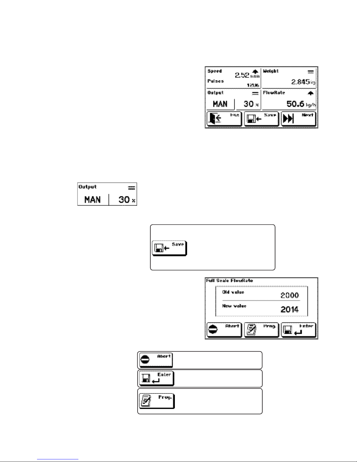
Pag. 47
MC 353 software 1.9
ENG
4
4.4 - MACHINE TEST PROCEDURE
Through this procedure it is possible to define one precise correspondence between the flow rate and
the speed adjustment analogue output signal.
In correspondence to a speed value within 20% and
80% it is possible to save the real flow rate value;
this allows to assume already from the first start the
speed value corresponding to the required setpoint
and to speed up the adjustment.
This procedure is not compulsory because usually the
maximum speed is associated with the value saved in
the Maximum Flow Rate and shall not be performed
if the instrument is set as Transmitter.
During the test no adjustment is carried out and the I/O are not managed. It is furthermore necessary to
make sure that the passing product is constant and that the working conditions are the standard ones.
Set the speed value in manual mode (20% ÷ 80%).
Start the belt and make sure the product is constant.
After saving the current hourly flow rate the display
shows the value corresponding to the calculated scale
end and the previous value.
With output within 20% and 80%
this key allows you to save the
detected ow rate, to calculate
the real ow rate at scale end
according to a linear proportion.
It rejects the calculated value
and restores the old one.
It conrms the new calculated
ow rate scale end.
It enters the manual set-up of
the ow rate scale end value.
TECHNICAL MENU -> MACHINE TEST

Pag. 48
MC 353 software 1.9
ENG
5
5 - sYsTeM calIbRaTIon
5.1 - BELT HOMING DYNAMIC PROCEDURE
This procedure allows to reset the weighing system
tare with moving belt.
The procedure duration is determined by the time/
length values set in the relevant parameter (we recommend a value corresponding to one complete cycle).
At the end of the procedure the zero calibration is
automatically saved by considering the mean of all
sampled weights.
During the zero calibration stage the belt must move
empty (without product).
The weighing belt calibration is a fundamental stage to get a correct measure and shall always be
carried out; it is furthermore necessary to repeat it periodically and each time you carry out mechanical
adjustments on the belt.
The calibration consists of two phases:
1) Zero calibration that allows to acquire the system tare and can be carried out both with moving belt
(recommended procedure) and with stopped belt;
2) scale end calibration that can be carried out both with a product (recommended procedure) and
with a sample weight.
Note: before proceeding with the calibration make sure to have correctly set the flow rate parameters
of cells, sensitivity, maximum flow rate and belt inclination (parameters 0154, 0160, 0152, 0159).
Press the PROG key to enter the set-up menu and enter the values corresponding to
one complete cycle of the belt through the parameters (operative mode, cycle time
or length).
Note: this operation shall be carried out only the first time since the parameters remain in memory.
Only in case the instrument is set as regulator you shall set the speed at
which you want to carry out the test by means of the special control.
Check that the belt is completely empty.
It starts the weight reset procedure; to do this you will be asked to enter a password
(if set).
Once the reset procedure is started the system waits for the run input closure and, when it detects the
belt movement through the encoder, it measures the belt cycle time or length. The measure that remains
at the end of the procedure is displayed as decreasing in the state section. It is possible to interrupt at
any time the procedure by the touch screen without modifying the weight calibration. At the end of the
reset tare value is displayed in the relevant menu of the parameters.
It quits the procedure and goes back to the technical menu.
TECHNICAL MENU -> SYSTEM CALIBRATION -> BELT HOMING

Pag. 49
MC 353 software 1.9
ENG
5
5.2 - BELT CALIBRATION DYNAMIC PROCEDURE
TECHNICAL MENU -> SYSTEM CALIBRATION-> BELT CALIBRATION
This procedure calibrates the belt with product by
getting a K correction factor.
During the test a certain quantity of product is conveyed on the belt (the product could be recovered
at outfeed and weighed on the static balance) and
the correspondence between real and calculated
weight is checked.
The K factor is calculated by the instrument as a ratio between the total weight calculated by the same
and the one actually conveyed detected and set by the operator.
Before starting the test, reset all values by pressing the relevant section.
Only in case the instrument is set as regulator you shall set the speed at
which you want to carry out the test.
Start the belt by closing the run input and pass the quantity of product necessary for the test and then
stop the belt.
It enters the real conveyed weight set-up in case the value does not correspond to the
one calculated by the instrument.
After setting up the detected real weight the display shows the calculated K correction
factor and the previous value.
It confirms the correction value.
It rejects the value and restores the previous one.
The reset procedure can also be activated by a remote control using the saved parameters only in stop
conditions. The control can be transmitted by the serial line (5001 parameter), or by the logic input
(input 5). The procedure modes are the same of the manual one but with set maximum resettable value
(0135); at the end the general window is restored.
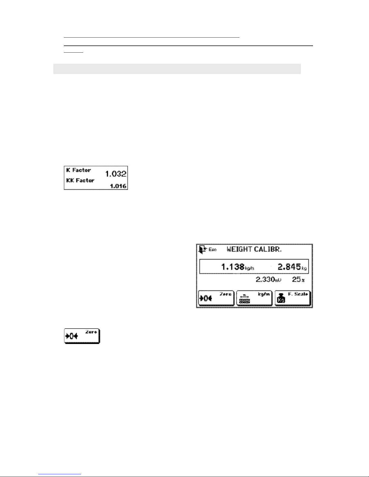
Pag. 50
MC 353 software 1.9
ENG
5
5.3 - ZERO STATIC CALIBRATION AND WITH SAMPLE WEIGHT
TECHNICAL MENU -> SYSTEM CALIBRATION -> WEIGHT CALIBRATION
Note: during the calibration test it is necessary to follow the rule below:
if you start with empty belt you must finish with empty belt, if you start with full belt you must finish with
full belt.
This procedure shall be used in case it is not possible
to carry out the reset with moving belt or the calibration of belt with product.
The detected weight is first of all determined by
the nominal flow rate parameters and the cell sensitivity (parameters 0154 and 0160); furthermore
the calibration is influenced by the belt inclination
(parameter 0159).
ZERO CALIBRATION
CALIBRATION wITH SAMPLE wEIGHT OR CHAINS
With this key you start the ZERO CALIBRATION; make sure that the belt is empty
(without product) and the weight is stable, then press the key to save the detected
value as system tare.
Once the zero value has been saved it is possible to check/calibrate the system by using one sample
weight (knowing its total weight) or chains (knowing the weight per meter).
For this procedure it is necessary to put the weight or the chains in the weighing area and check the
weight displayed on the instrument. In case of significant differences proceed with the calibration.
CORRECTION FACTOR MANUAL CALCULATION AND SET-UP
This function allows to manually set the “correction factor”; this is useful when you have production data
and you wish to correct the calibration without carrying out a specific test.
The new correction factor (K) shall be calculated as follows:
K = K1 x REAL TOTAL / CALCULATED TOTAL
Where :
CALCULATED TOTAL = value of calculated weight displayed by the instrument
REAL TOTAL = value of weight actually conveyed on the belt
K1 = correction factor saved in the instrument during the test
In page 2 of the belt calibration window it is possible to see the saved K
factor and to enter directly the set-up of the previous calculated value by
pressing the relevant section.
If enabled, it will be programmed in sequence the KK factor.

Pag. 51
MC 353 software 1.9
ENG
5
1
2
3
4
5
6
7
8
9
10
9
4
3
2
5
6
7
8
1
10
4
4
6
4
4
4
4
4
4
5
Cod.
Description
Priority
Activation
OUT
Message
NO
NO
NO
Par. 1030
NO
Par. 1030
Par. 1030
NO
Active in
STOP
Adjustment impossible: scale end output
insufcient for obtaining the required
hourly ow rate.
No encoder signal after 3 consecutive
sampling periods.
According to the activation parameter
selection there are different activation
conditions. FLOW RATE 0: null hourly
ow rate for speed=0, or weight lower
than the minimum one. MIN. WEIGHT:
weight lower than the minimum one
with moving belt (null hourly ow rate).
Load cell signal missing or out of scale.
Weight on the belt stuck on a xed
value for the set time.
Probus module connection error
Probus comunication CRC error
Probus network connection error
Power supply <20Vdc
Tolleranza Alarm
Par. 1025
Par. 1026
Par. 1022
ALWAY S
Par. 1042
Probus
Protocoll
selected
ALWAY S
Par. 1029
Adjustment al.
Encoder al.
Min. weight al.
or
Encoder al.
Load cell al.
Fixed weight
al.
Err. Probus
CRC Probus
NoCom. Probus
Alr. VDC
Alr. toll.
5.4 - MC 353 OPERATION ALARMS
During RUN the following alarms may occur, shown in the display’s dedicated area, up to the right,
with a blinking icon, beyond the activation of the relevant output. All
alarms deactivate automatically when the cause ceases to exist and normal
function is established, but blinking icon still stays on until manual RESET
occurs (press the dedicated virtual button) or until the next RUN START
(except out-of-tolerance alarm which ceases automatically by itself). The
alarms linked with an external input module are active if each input is associated with an alphanumeric
description (they have low priority; among them the highest priority goes to input 1 on module 1 while
the least goes to input 4 on module 2).
With this key you enter the sample weight loaded on the belt (in Kg/m) usually made up of
chains placed on the whole weighing area whose weight per meter is known.
OR
It allows to enter the sample weight loaded on the belt (in Kg); usually one roller placed near
the load cells axis.

Pag. 52
MC 353 software 1.9
ENG
5
STX A <value> ETX <chk> EOT
5.5 - DENSITY CALIBRATION PROCEDURE
Density calibration consist in programming parameter Specific Weight and register a weight value for
“Peso Mem”. These values are used for actual density calculation according the formula indicated at
the next chapter.
Press box on display to setup the specific
weight
Press box on display to setup the actual weight
DENSITY CALCULATION
Density parameter is calculated according the actual weight detection, based upon the following formula:
WEIGHTmem : PS = actualWEIGHT : D
Where:
- WEIGHTmem: calibration weight value recorded during density calibration
phase;
- PS: specific weight;
- actualWEIGHT: actual detected weight;
- D: calculated density.
Density is transmitted to the 3rd analogue output (*). To enable data transmission, set, through “SYSTEM
SETUP” the parameter “3rd ANALOGUE OUTPUT” = YES. Also, set parameter “FS DENSITY” at the
value you wish to associate to the upper limit of the analogue output.
Density, specific weigh and full scale density are expressed in kg/dm3 units with 3 decimals and upper
value 2000 kg/dm3 (*) 3rd analogue output is a serial data transmission to a D/A converter (code
SW P12043) which receives digital data to convert to analogue output (tension or current depending
upon D/A converter’s configuration). Further details on the specific manual.
Serial transmission is held on COM3 (parameters 9600, N81, frequency 5Hz). Transmitted string:
<value> 5 numeric digits for density, related to the full scale according the formula:
Density : FSdensity = <value> / 10000
When the 3
rd
analogue output is active, parameter “protocollo COM3” is forced to NUL

Pag. 53
MC 353 software 1.9
ENG
6
TTTTT ; FFFFFF ; SSSSSS ; PPPPPPPP ; WWWWWWW ; M ; RRR ; A CR LF
6.1 - DATA LOGGER
6 - aDDITIonal fUncTIons of Mc 353
This function can be enabled by the technical menu and allows to continuously record run operative
data to analyse the system behaviour over time. The provided data are the following:
Actual time of the sampling period in ms TTTTT (5 car.)
Instantaneous hourly flow rate FFFFFF (6 car.)
Belt speed in cm/min SSSSSS (6 car.)
Number of encoder counted pulses PPPPPPPP (8 car.)
Detected weight WWWWWWW (7 car.)
Manual / automatic operation selectio M (1 car.)
Analogue output value in percentage RRR (3 car.)
Alarm code A (1 car.)
When each sampling period elapses one data record is sent in the following format (CSV compatible).
In the technical menu it is possible to activate the Data Logger function to transmit the data record in data
stream on COM2 (with USB, RS232 or R485 interface). These data are available for a PC application
that stores it in a file for a future analysis, displays it on a monitor screen or shows it in graphic format
to highlight the trend over time.
If a the USB Host option is available the data records can be directly saved in a CSV file that is automatically named logxxxx.csv, where instead of x you will find a progressive number. At the file start and
end the system adds a line with current date and time. In this case the USB pen drive shall be inserted
during the data logging operation.
If you selected the data logger operation on USB file, it is automatically disabled after 3600 records,
to avoid having files with a great amount of data in case the function is forgotten active.
6.2 - SAVE AND LOAD SET-UP
With the set-up files saving and loading operations (available in the set-up menu) all parameters that can
be set can be transferred from the instrument memory to a PC or a USB memory support and vice versa.
This function can be used to save a copy of the parameters, to store the set-up of one system instrument,
to duplicate the same set-up on more instruments, to receive the set-up files of a remote system through
the web for technical reasons.
The data transfer occurs on the COM2 communication port (RS485, RS232 or USB device). In case the
USB Host option is available and set, the file transfer occurs directly on the USB (pen drive) memory
support.
The transferred data are those indicated in the parameters table and identified with the univocal address.
The file format is CSV, made up of one table with one parameter per line and 2 columns indicating the
parameter address and value.
<address> ; <value> CR LF
TECHNICAL MENU -> DATA LOGGER
set-up MENU -> SAVE set-up / LOAD set-up

Pag. 54
MC 353 software 1.9
ENG
6
In case of transfer on COM2 the load function waits to receive one file whereas the saving function
sends data directly to the communication port without waiting handshake operations: the receiving unit
must be able to receive data when the control is activated.
In case of transfer on USB pen drive, the memory support shall be entered before the activation of the
saving and loading controls. The transferred file has a fixed name: set-up.csv.
The data loading could also be partial, i.e. the table can contain only some parameters (or even just
one) and they must not be compulsorily ordered as in the table created by the instrument with the saving
operation.
This offers an alternative system for setting up the parameters.
6.2 - FILE LOADING
The file loading operation (available in the set-up menu) allows to set the instrument so as to customise
some functions. The display shows a control menu and each control corresponds to one file to be loaded
in the instrument.
There are 10 contextual Help text files available that can be transferred from the instrument memory to
the PC or a USB memory support and vice versa.
H01.TXT Help text waiting for controls of the main window
H02.TXT Help text in numeric data set-up
H03.TXT Help text in selectable data set-up
H04.TXT Help text for warning or confirmation windows
H05.TXT Help text in the total section
H06.TXT Help text in the setpoint section
H07.TXT Help text in the hourly flow rate section
H08.TXT Help text in confirmation of the calculated K correction factor
H09.TXT Help text in the default zero weight calibration function
H10.TXT Help text in the default 2mV/V weight calibration function
SPLASH.BMP Image displayed upon instrument switching-on
SETPOINT.TXT Names associated with the setpoints
INEXT.TXT Descriptions associated to logic inputs of external modules
The files loading occurs on the COM2 communication port (RS485, RS232 or USB device). In case the
USB Host option is available and set, the file loading occurs directly on the USB (pen drive) memory
support.
The Help texts are ascii files with max. length of 300 characters.
The splash.bmp file shall necessary be a black and white bitmap file (1 bit of colour depth), with fixed
dimensions 120 x 40.
The setpoint.txt file is a text constituted by 1 to 15 text lines corresponding to setpoints from 1 to 15.
Each setpoint name can feature maximum 10 characters.
File inext.txt is a text file composed of 1 to 8 text lines, corresponding to descriptions assigned to inputs
from 1 to 8 (4 + 4) on the two external I/O modules. Each description can be composed by up to 16
characters (we recommend to check the visualization on the display, which may vary according to the
used characters).
In case of loading from COM2 the loading function waits to receive one file.
In case of loading from USB pen drive, the memory support shall be inserted before the activation of
the loading controls.
set-up MENU -> FILES LOADING

Pag. 55
MC 353 software 1.9
ENG
6
4
TX
5
CTS
3
GND
5
3
8
6.3 - RECEIPT PRINT
( OPTIONAL PRINTER )
When the input 6 set for total reset is closed and the
printer is selected a receipt like the one shown in the
picture will be released.
Date and time of the last reset (new totalization start)
and the current date and time are reported. The instrument serial address is indicated at the top right.
The printer shall use a 56/57 mm paper reel with
RS232 interface.
In case the printer is not connected or it is off the total
is not reset.
The printer DTR signal must be connected to the instrument CTS signal.
NUM.
Upper terminal block
(pitch 5.08 mm)
Data transmission
cts
Signal mass
PRINTER
mod. SP 190
pin
6.4 - ANALOGUE MODULE
( OPTIONAL)
MC 353 instrument can handle up to 3 external analogue modules. Transmittable data may be density,
speed and weigh (or weigh per meter)
Full scale reference can be set through page “SYSTEM SETUP” (parameters “FS Speed”, “FS Weigh”,
“FS Density”.
For further details see the specific manual.
6.5 - RELAY MODULE
Relay module MOD-RELE’, connected through COM2 (RS485) to the MC 353 instruments, can handle
an additional 8 outputs and 4 inputs.
Each MC 353 instrument can be connected to a total of 2 relay modules at the same time, handling
this way up to 16 outputs and 8 inputs.
INPUTS: Relay module, through serial port, transmits status of inputs to MC 353 instrument. The input
status is converted to specific registry status of inputs on the ModBus/Profibus registry.
It is possible to program the instrument so the status of a certain input on the relay module may generate
a general alarm on MC 353 instrument.
ON status of inputs does not involves other operating procedures on the instrument.
OUTPUT: status of module’s output is determined by the ModBus/Profibus registry, transmitted to the
PC/PLC by MC 353 instrument.
For further details see the specific manual.
( OPTIONAL)

Pag. 56
MC 353 software 1.9
ENG
7
7 - seRIal coMMUnIcaTIon anD PRoTocols
7.1 - ASCII COMMUNICATION PROTOCOL
Baud rate and format data according to the selection on the TECHNICAL MENU.
RS485 interface with 2 twisted pairs.
The communication protocol requires always the transmission of a string by the PC with the address
of the control receiver instrument and a response string by the receiving instrument. The delay of the
response string can be of 15 ms.
The following parameters are common in the strings description below:
ADDR = receiver address (80h + address number; for eg. address 1: to = 81h)
ETX = end of text (03h)
EOX = end of text (04h)
ACK = acknowledgement (06h)
NAK = NO acknowledgement (15h)
<CC> = check sum calculated from ADDR to ETX excluded; they are 2 ASCII characters of the hexa-
decimal notation resulted from the characters XOR operation.
<CMD>= control identification constituted by one ASCII character (one capital letter).
A) FLOW RATE SETPOINT SET-UP
A) FLOW RATE SETPOINT READING
C) SETPOINT SELECTION
D) SETPOINT TOLERANCE SET-UP
E) SET-UP TOLERANCE READING
F) CONVEYED TOTAL SETPOINT SET-UP
G) CONVEYED TOTAL SETPOINT READING
H) CONVEYED TOTAL SETPOINT RESET
I) MANUAL / AUTOMATIC SELECTION
J) ADJUSTMENT PARAMETERS SET-UP
K) ADJUSTMENT PARAMETERS READING
The controls are available in all conditions of the instrument except for the controls A, D, F, J, O during
the set-up of the relevant parameters through the keyboard:
- The control A is not available in case you are setting-up the setpoint corresponding to the transmitt
done through the keyboard.
- The control D is not necessary in case you are setting-up the tolerance through keyboard.
- The control F is not necessary in case you are setting-up the conveyed total through keyboard.
- The control J is not necessary in case you are setting-up one adjustment parameter through the keyboard
corresponding to on of those transmitted.
-The control O is not necessary in case the instrument is in the run condition or a data set-up procedure
is in progress.
In case of unavailability the instrument will send a suitable response control.
ASCII PROTOCOL CONTROLS LIST

Pag. 57
MC 353 software 1.9
ENG
7
L) INSTRUMENT STATE READING
M) SYSTEM MAX. FLOW RATE READING
M0) PERCENTAGE CHANGE OF THE FLOW RATE SETPOINT (from WTLW)
N) PRODUCT CORRECTION COEFFICIENT SET-UP
O) RESET FUNCTION OF MOVING BELT
P) INSTANTANEOUS ANALOGUE OUTPUT PERCENTAGE READING
M) SYSTEM MAX. FLOW RATE READING
M0) PERCENTAGE CHANGE OF THE FLOW RATE SETPOINT ( from WTLW)
N) PRODUCT CORRECTION COEFFICIENT SET-UP
O) RESET FUNCTION OF MOVING BELT
P) INSTANTANEOUS ANALOGUE OUTPUT PERCENTAGE READING
The controls are available in all conditions of the instrument except for the controls A, D, F, J, O during
the set-up of the relevant parameters through the keyboard:
- The control A is not available in case you are setting-up the setpoint corresponding to the transmitt
done through the keyboard.
- The control D is not necessary in case you are setting-up the tolerance through keyboard.
- The control F is not necessary in case you are setting-up the conveyed total through keyboard.
- The control J is not necessary in case you are setting-up one adjustment parameter through the keyboard
corresponding to one of those transmitted.
- The control O is not necessary in case the instrument is in the run condition or a data set-up procedure
is in progress.
In case of unavailability the instrument will send a suitable response control.
All strings transmitted to the MC 353 have the following format; also the MC 353 response strings have
the same format except the error one, the not available control string and the acknowledgement one.
String type ADDR <CMD> <data> ETX <CC> EOT
Acknowledgement string ADDR <CMD> ACK EOT
Communication error or unacceptable data string ADDR NAK EOT
Not available control string ADDR “#” EOT
According to the system maximum flow rate value the instrument determines automatically the flow rate
unit of measurement, the resolution, the totalizator decimals described in the table under chapter 3.7.
COMMUNICATION STRINGS FORMAT

Pag. 58
MC 353 software 1.9
ENG
7
A) Flow rate setpoint set-up
The PC transmits: ADDR “A” <N> <XXXX> ETX <CC> EOT
Where :
<N> = number of setpoint (from ”1” to ”9” and from ”A” to ”F” for set point from 10 to 15)
<XXXX> = flow rate set point without decimal point
The MC 353 answers: ADDR “A” ACK EOT
B) Flow rate setpoint reading
The PC transmits: ADDR “B” <N> <XXXX> ETX <CC> EOT
Where :
<N> = number of setpoint (from ”1” to ”9” and from ”A” to ”F” for set point from 10 to 15)
The MC 353 answers: ADDR “B” <N> <XXXX> ETX <CC> EOT
Where :
<XXXX> = flow rate setpoint
C) Setpoint selection
The PC transmits: ADDR “C” <N> <XXXX> ETX <CC> EOT
Where :
<N> = number of setpoint (from ”1” to ”9” and from ”A” to ”F” for set point from 10 to 15)
The MC 353 answers: ADDR “C” ACK EOT
D) Setpoint tolerance set-up
The PC transmits: ADDR “D” <N> <XXXX> ETX <CC> EOT
Where :
<XXXX> = set point tolerance without decimal point
The MC 353 answers: ADDR “D” ACK EOT
E) Setpoint tolerance reading
The PC transmits: ADDR “E” <N> <XXXX> ETX <CC> EOT
The MC 353 answers: ADDR “E” <N> <XXXX> ETX <CC> EOT
Where :
<XXXX> = set point tolerance without decimal point
F) Preset and flight conveyed total setpoint set-up
The PC transmits: ADDR “F” <XXXXXXX> <PPPPPPP> <VVVVVVV> ETX <CC> EOT
Where :
<XXXX> = total set point without decimal point
<PPPPPPP> = total preset without decimal point
<VVVVVVV> = total flight without decimal point
The MC 353 answers: ADDR “F” ACK EOT

Pag. 59
MC 353 software 1.9
ENG
7
G) Conveyed total setpoint reading
The PC transmits: ADDR “G” <N> <XXXX> ETX <CC> EOT
The MC 353 answers: ADDR “G” <XXXXXXX> <PPPPPPP> <VVVVVVV> ETX <CC> EOT
Where :
<XXXX> = total setpoint
<PPPPPPP> = total preset without decimal point
<VVVVVVV> = total flight without decimal point
H) Conveyed total setpoint reset
The PC transmits: ADDR “H” <N> <XXXX> ETX <CC> EOT
The MC 353 answers: ADDR “H” ACK EOT
I) Manual / automatic selection
The PC transmits: ADDR “I” <N> <XXXX> ETX <CC> EOT
Where :
<N> = (“A” = automatic, “M” = manual)
<XXX> = output value in manual mode (from 0% to 100%)
- with <N> = “A” : <XXX> = ”000”
- with <N> = “M” : <XXX> from 0 to 100 it selects the instrument in manual
mode with manual analogue output equal to <XXX>.
- with <N> = “M” : <XXX> higher than 100 it selects manual mode
by keeping the analogue output already existing.
The MC 353 answers: ADDR “I” ACK EOT
If it is possible to select in manual mode (in case of external regulator) it answers with NAK.
J) Adjustment parameters set-up
The PC transmits: ADDR “J” <PPP> <XX> <BBBB> ETX <CC> EOT
Where :
<PPP> = proportional constant from 0 to 250.
<XX> = constant integration from 1 to 10.
<BBBB> = absolute value of dead belt.
The MC 353 answers: ADDR “J” ACK EOT
K) Adjustment parameters reading
The PC transmits: ADDR “K” <N> <XXXX> ETX <CC> EOT
The MC 353 answers: ADDR “K” <PPP> <XX> <BBBB> ETX <CC> EOT
Where :
<PPP> = proportional constant from 0 to 250.
<XX> = constant integration from 1 to 10.
<BBBB> = absolute value of dead belt.

Pag. 60
MC 353 software 1.9
ENG
7
L) Instrument state reading
The PC transmits: ADDR “L” <N> <XXXX> ETX <CC> EOT
The MC 353 answers: ADDR “L” <M> <F> <PPPP> <XXXXXXX> ETX <CC> EOT
Where :
<M> = (run state = “1” or stopped belt = “0”)
<F> = operation type (A = automatic, M = manual)
<PPPP> = instantaneous flow rate
<XXXXXXX> = partial total
M) System max. flow rate reading
The PC transmits: ADDR “M” <N> <XXXX> ETX <CC> EOT
The MC 353 answers: ADDR “M” <XXXX> ETX <CC> EOT
Where :
<XXXXXXX> = 6 characters of max. flow rate in kg/h
M0) Flow rate setpoint percentage change
The PC or the WTLW transmits: ADDR_0 “M” <XXXX> ETX <CC> EOT
This string shall contain the address 0 to be recognised. The MC 353 does not transmit any string
neither in case of performed control nor in case of error. The percentage value received is related to
the maximum flow rate value.
Where :
<XXXX> = max. flow rate thousandths
N) PRODUCT CORRECTION COEFFICIENT SET-UP (KK)
The PC transmits: ADDR “N” <XXXX> ETX <CC> EOT
Where :
<XXXX> = correction coefficient without decimal point
The MC 353 answers: ADDR “N” ACK EOT
O) RESET FUNCTION OF MOVING BELT
The PC transmits: ADDR “O” <XXX> <Y> <ZZZZZ> ETX <CC> EOT
Where :
<XXX> = output value in manual mode (from 0% to 100%)
<Y> = selection of belt cycle time “T” or length “L”
<ZZZZZ> = belt cycle time in seconds or belt length in cm
The MC 353 answers: ADDR “O” ACK EOT
P) INSTANTANEOUS ANALOGUE OUTPUT PERCENTAGE READING
The PC transmits: ADDR “P” ETX <CC> EOT
The MC 353 answers: ADDR “P” <XXXX> ETX <CC> EOT
Where :
<XXX> = 3 characters of instantaneous analogue output percentage

Pag. 61
MC 353 software 1.9
ENG
7
Register
value
Decimal no.
Measure Unit
1 2 3 4 5 6
1 2 3 1 2 3
kg - kg/h kg - kg/h kg - kg/h T - T/h T - T/h T - T/h
7.2 - MODBUS COMMUNICATION PROTOCOL
The complete list of MODBUS controls and protocol addresses are reported in the table at pages 34,
35 and 36.
NOTE: The MODBUS-RTU specifications foresee that the 40001 register is allocated the address 0000.
Master’s timeout duration for each query sent must be at least 25 ms. At this time add query’s transmission time and the response time. Both depend upon the baud rate.
Master must be able to resume functioning after a communication fault (unknown string or framing error)
5001 Command Reg: program registry with the corresponding value according to the command you
want to issue:
1 = reset total
2 = reset belt
3 = save data
5002 RUN Command Reg: program registry with the corresponding value according to the command
you want to issue:
bit15 indicates protocol command priority against logic input 01 for run (1=run is piloted by
protocol, 0=run is piloted by logic input);
bit0 indicated command status (1=run, 0=stop)
I.e: by programming the value 0x8001, instrument is in RUN (bit0 = 1) and ignores status of logic
input (bit15 = 1).
3018 - input status:
bit15-6 bit5 bit4 bit3 bit2 bit1 bit0
— in6 in5 in4 in3 in2 in1 (0 = open, 1 = close)
3019 - output status:
bit15-6 bit5 bit4 bit3 bit2 bit1 bit0
— out6 out5 out4 out3 out2 out1 (0 = not active, 1 = active)
3030/3031: based on the value of the registers 3030 and 3031 can be identified units and no. decimal of data flow and total. For coding use the following table:
MODBUS/PROFIBUS REGISTERS NOTES

Pag. 62
MC 353 software 1.9
ENG
7
pin
7
9
6
4
/
nr.
11
10
9
8
/
Probus-CV
MC 353
TXD-
TXD+
RXD-
RXD+
GND
RXD-
RXD+
TXD-
TXD+
GND
(COM1 RS422)
7.3 - PROFIBUS-DP / PROFINET IO COMMUNICATION PROTOCOL
PROFIBUS interface may be installed either internally or externally to the instrument (in later case module
S125 is used, connected through COM 1 serial port Rs422)
PROFINET interface is internally installed only.
Connection between MC 353 and Profibus-CONV module:
OPTIONAL MODULE
Power supply
Consumption
Working temperature
Humidity
Storage temperature
Dimension
Mounting
IP protection
RS422 max lenght
Probus max lenght
12/24Vcc (+/-5%)
2W (80mA max)
-10°C ÷ +40°C
max 85% condensate free
-20°C ÷ +50°C
71 x 90 x 58 mm
Omega/DIN rail
IP40
500m
Network dependent
Regardless mounting position, communication between the instrument and PROFIBUS or PROFINET
interfaces uses ModBus RTU serial protocol. Address (slave ModBus) of the module is fixed at 01,
communication baud rate is fixed at 38400 bit/s and forced upon selection of protocol PROFIBUS or
PROFINET on COM1.

Pag. 63
MC 353 software 1.9
ENG
7
ERROR MANAGEMENT (Ref. Par. OPERATING ALARMS)
[Err. PROFIBUS] Communication failure error between Modbus and S125 module :
after 5 consecutive communication time-outs. A communication reset is automatically executed, but if
it fails the error is displayed and you can manually reset the error by pressing the RESET push-button.
[NoCom. PROFIBUS] Off-Line PROFIBUS network error: for example in case of failed connection of S125
module with the Profibus network. This error is automatically muted upon standard connection reset.
[CRC PROFIBUS] CRC error in Modbus communication.
The timeout on module answer is fixed at 100mS.
RESET PROCEDURE FOR EXTERNAL MODULE (S125)
As no hardware reset line is available, module shall be switched off
and on after the following operations:
- module first connection to the instrument;
- following changes of PROFIBUS address.
When the module is internal, such procedure is automatically handled by the software.
INPUT and OUTPUT AREA MANAGEMENT: module’s default setting is a fixed configuration of input
and output areas. Programmable parameters are identified and listed on a list included in module’s
manual. Eventually, through a specific application (PWIN 75) is possible to configure I/O areas of
PROFIBUS DP and PROFINET IO field buses, in order to obtain an ordered list of parameters to meet
application specifications. The GSD, GSDML files and PWIN 75 application are available in our web
site under the ‘download’ area.
INPUT DATA AREA - Parameter reading
- INPUT AREA SIZE = 128 bytes [64 Registers]
The INPUT DATA AREA page is selected by writing the corresponding value inside the command register,
as per the following table:
COMMAND REGISTER Table
Value
01
02
Command
Selection INPUT DATA AREA page 1
Selection INPUT DATA AREA page 2
OUTPUT DATA AREA - Parameter writing
- OUTPUT AREA SIZE = 64 bytes [32 Registers]
- Single parameter programming: write the value inside the general programming registers H and L,
then write the address corresponding to the parameter to be programmed
inside the command register (address of the L part in case of 4-byte parameters).
Ex. Programming of a 50 value in the “Manual Out” parameter: write 0 in bytes 2-3, write 50 in bytes
4-5, then write 4013 in bytes 0-1 (command register). This, of course, applies also to the command
register: write the command value in bytes 2-3 and 4-5, then write 5001 in registers 0-1.
To code registries 5001, 5002, 3018, 3019 follow instructions provided in page 61.
EXAMPLE (programming registry 5001 to send command of total reset):
write to bytes 2-3 of OutputDataArea value 0;
write to bytes 4-5 of OutputDataArea value 1;
write to bytes 0-1 of OutputDataArea value 5001.

Pag. 64
MC 353 software 1.9
ENG
7
Value
4010
2040
2000
1000
1040
150
10
5000
32767
Table COMMAND REGISTER
INPUT DATA AREAS
Variables
Input page number
Flowrate
Total H
Total L
Grand Total H
Grand Total L
Setpoint
Alarm Code
Input
Output
Speed H
Speed L
Current Weight H
Current Weight L
Analog Out 1
Analog Out 2
Analog Input
Address
6001
3011
3012
3013
3014
3015
3016
3017
3018
3019
3020
3021
3022
3023
3024
3025
3026
Map. bytes
0-1
2-3
4-5
6-7
8-9
10-11
12-13
14-15
16-17
18-19
20-21
22-23
24-25
26-27
28-29
30-31
32-33
- Programming of the whole OUTPUT DATA AREA: write the desired values in the corresponding registers, then write the command for the programming of the whole AREA in the command register, based
on the following command register reference table.
- The OUTPUT DATA AREA page is automatically selected based on the value written in the command
register.
- Parameters programming is effective only if the instrument is in the basic mask displaying mode.
NOTE: by writing on command register the 7FFFh command, the customization of output area is enabled. All the following registries (depending upon the chosen configuration) are directly accessible.
Command
Total programming OUTPUT DATA AREA page 1
Total programming OUTPUT DATA AREA page 2
Total programming OUTPUT DATA AREA page 3
Total programming OUTPUT DATA AREA page 4
Total programming OUTPUT DATA AREA page 5
Total programming OUTPUT DATA AREA page 6
Total programming OUTPUT DATA AREA page 7
Total programming OUTPUT DATA AREA page 8
Enabling the custom output area
INPUT DATA AREA [01] - Continua pag. successiva

Pag. 65
MC 353 software 1.9
ENG
7
INPUT DATA AREA [01]
Address
3027
3028
3029
3030
3031
4011
4012
4013
4014
2041
2042
2043
2045
2047
2049
2051
2053
2055
2057
2059
2061
2063
2065
2067
2069
2001
2002
2003
2004
2005
2006
1001
1002
1003
1004
1005
1006
1007
Variables
Test Status
Run Status
Flow rate decimals
Total decimals
Weight decimals
Num. Set
Auto / Man
Manual Out
Var. Setpoint
Setpoint 1
Manual Out Set 1
Setpoint 2
Setpoint 3
Setpoint 4
Setpoint 5
Setpoint 6
Setpoint 7
Setpoint 8
Setpoint 9
Setpoint 10
Setpoint 11
Setpoint 12
Setpoint 13
Setpoint 14
Setpoint 15
Total Set H
Total Set L
Total Preset H
Total Preset L
Total Flying H
Total Flying L
Sampling Time
Proportional Constant
Cost. Integrale
Dead Band
Flowrate Limit
Dead Band %
Flowrate Limit %
Mapp. bytes
34-35
36-37
38-39
40-41
42-43
44-45
46-47
48-49
50-51
52-53
54-55
56-57
58-59
60-61
62-63
64-65
66-67
68-69
70-71
72-73
74-75
76-77
78-79
80-81
82-83
84-85
86-87
88-89
90-91
92-93
94-95
96-97
98-99
100-101
102-103
104-105
106-107
108-109

Pag. 66
MC 353 software 1.9
ENG
7
INPUT DATA AREA [01]
Address
1041
1042
1043
1044
1045
1063
5002
7001
Variables
Stop Delay
Timeout Peso
Regolation Delay
Flow Limit Delay
Limit Init Delay
Min. Weight
Run Command Reg.
Test Register
Mapp. bytes
110-111
112-113
114-115
116-117
118-119
120-121
122-123
124-125
INPUT DATA AREA [02]
6001
11
131
132
133
134
135
141
143
151
152
163
164
181
182
7001
3032
3033
3034
3035
4015
4016
4017
4018
4019
Input page number
Operat. Function
Operating mode
Revolution time
Revolution length
Ta r e
Max. remote tare
K factor
KK factor
Max. Flowrate H
Max Flowrate L
Dead Band Unit
Tolerance Unit
Real Max. Flowrate H
Real Max. Flowrate L
Test Register
Weigh / meter H
Weigh / meter L
Density
System Ready
Specic gravity
Module IO EXT. 1 INPUT
Module IO EXT. 1 OUTPUT
Module IO EXT. 2 INPUT
Module IO EXT. 2 OUTPUT
0-1
2-3
4-5
6-7
8-9
10-11
12-13
14-15
16-17
18-19
20-21
22-23
24-25
26-27
28-29
30-31
32-33
34-35
36-37
38-39
40-41
42-43
44-45
46-47
48-49

Pag. 67
MC 353 software 1.9
ENG
7
OUTPUT DATA AREA [02]
Address
5001
-
-
7001
2041
2042
2043
2045
2047
2049
2051
2053
2055
2057
2059
2061
2063
2065
2067
2069
Mapp. bytes
0-1
2-3
4-5
6-7
8-9
10-11
12-13
14-15
16-17
18-19
20-21
22-23
24-25
26-27
28-29
30-31
32-33
34-35
36-37
38-39
Variables
Command Register
General register for H parameter programming
General register for L parameter programming
Test Register
Setpoint 1
Manual Out Set 1
Setpoint 2
Setpoint 3
Setpoint 4
Setpoint 5
Setpoint 6
Setpoint 7
Setpoint 8
Setpoint 9
Setpoint 10
Setpoint 11
Setpoint 12
Setpoint 13
Setpoint 14
Setpoint 15
OUTPUT DATA AREAS
OUTPUT DATA AREA [01]
5001
-
-
7001
4011
4012
4013
4014
4015
4016
4017
4018
4019
Command Register
General register for H parameter programming
General register for L parameter programming
Test Register
Set number
Auto / Man
Manual Out
Var. Setpoint
Specic gravity
Module IO ext. 1 INPUT
Module IO ext. 1 OUTPUT
Module IO ext. 2 INPUT
Module IO ext. 2 OUTPUT
0-1
2-3
4-5
6-7
8-9
10-11
12-13
14-15
16-17
18-19
20-21
22-23
24-25

Pag. 68
MC 353 software 1.9
ENG
7
OUTPUT DATA AREA [04]
5001
-
-
7001
1001
1002
1003
1004
1005
1006
1007
Command Register
General register for H parameter programming
General register for L parameter programming
Test Register
Sampling Time
Proportional Constant
Cost. Integrale
Dead Band
Flowrate Limit
Dead Band %
Flowrate Limit %
0-1
2-3
4-5
6-7
8-9
10-11
12-13
14-15
16-17
18-19
20-21
OUTPUT DATA AREA [05]
5001
-
-
7001
1041
1042
1043
1044
1045
1063
Command Register
General register for H parameter programming
General register for L parameter programming
Test Register
Stop Delay
Timeout Peso
Regulation Delay
Flow Limit Delay
Limit Init Delay
Min. Weight
0-1
2-3
4-5
6-7
8-9
10-11
12-13
14-15
16-17
18-19
OUTPUT DATA AREA [03]
Address
5001
-
-
7001
2001
2002
2003
2004
2005
2006
Variables
Command Register
General register for H parameter programming
General register for L parameter programming
Test Register
Total Set H
Total Set L
Total Preset H
Total Preset L
Total Flying H
Total Flying L
Mapp. bytes
0-1
2-3
4-5
6-7
8-9
10-11
12-13
14-15
16-17
18-19

Pag. 69
MC 353 software 1.9
ENG
7
OUTPUT DATA AREA [07]
5001
-
-
7001
11
131
132
133
134
135
141
143
Command Register
General register for H parameter programming
General register for L parameter programming
Test Register
Operat. Function
Operating mode
Revolution time
Revolution length
Ta r e
Max. remote tare
K factor
KK factor
0-1
2-3
4-5
6-7
8-9
10-11
12-13
14-15
16-17
18-19
20-21
22-23
OUTPUT DATA AREA [08]
5001
-
-
7001
5002
0-1
2-3
4-5
6-7
8-9
Command Register
General register for H parameter programming
General register for L parameter programming
Test Register
Run command Reg.
PROFIBUS / PROFINET CONNECTION TEST PROCEDURE
Profibus Master (E.g. PLC) may verify connection of the instrument to Profibus network by the following
procedure:
1. Master writes a value (e.g. counter) on Test Register Out (bytes 6-7 of Output Area);
2. Instrument copies that value to Test Register In of Input Area;
Master verifies that the value read from input Area is the same value written at position 1
OUTPUT DATA AREA [06]
5001
-
-
7001
151
152
163
164
181
182
Command Register
General register for H parameter programming
General register for L parameter programming
Test Register
Max Flowrate H
Max Flowrate L
Dead Band Unit
Tolerance Unit
Real Max. Flowrate H
Real Max. Flowrate L
0-1
2-3
4-5
6-7
8-9
10-11
12-13
14-15
16-17
18-19

Pag. 70
MC 353 software 1.9
ENG
7
CUSTOM MAPING OF INPUT AND OUTPUT AREAS
It is possible to configure the PROFIBUS DP and PROFINET IO field buses I/O areas, to obtain an
ordered list of parameters according to the specific needs of the system.
This configuration is done using a specific utility (PCWIN 75) connected to the RS232/USB port COM2
of the instrument (communication parameters selectable).
The configurator PCWIN75 presents a user-friendly graphical environment through which compose the
areas of I / O: at each register can be associated with one parameter selected from a down list menu.
It is possible to customize up to 2 pages of INPUT and 1 page of OUTPUT.
The application can be downloaded in ns. website.
PROGRAMMING AREAS I / O (PC -> Touchscreen)
Through LOAD PROFI IO function, accessible from the setup menu when turned on, the touch screen is
enabled to receive the configuration.
Proceed with the submission of data by pressing the SEND button in the dialog of the configurator.
READING AREAS I / O (PC <- Touchscreen)
Set your PC to receive data by pressing the GET in the mask in the Configurator.
Using the SAVE PROFI IO function, accessible from the Setup Menu when turned on, the touch screen
will proceed with sending the configuration currently in memory.
RESTORE THE AREAS OF I / O TO DEFAULT
By entering the password in 1012 function (FACTORY SETUP) accessible from Setup Menu when turned on, you can restore the areas of INPUT to the default values or those in the following pages. This
operation will also lead to the cancellation of the customized OUTPUT .
COMPATIBILITY WITH PREVIOUS SW VERSIONS
Full compatibility with older software is ensured.
• Area of INPUT: thanks to the function that forces the configuration to default values
• Area OUTPUT: compatibility is guaranteed, because the meaning of the area registers always depends
on the value of the command register.
DETAILS MAPPING
• Area of INPUT: The first register of the Input always identifies the page number, the next 63 registers
are customizable. And it is possible but not mandatory to define up to two customized virtual pages.
• Area OUTPUT: The first register of the Output is always the Command Register.
Is maintained the logic according to which the value of the Command Register identifies the meaning
of the subsequent 63 registers available. A new command “activation area custom Output” (7FFFh) is
set: until the Command Register contains this command, the 63 following registers are directly accessible and match the custom parameters defined by the user. You can define only one single page of
customized output.

Pag. 71
MC 353 software 1.9
ENG
7
STX “M” XXXXXX.X ETX CC EOT
Flow rate percentage value with 1 decimal XXXXXX.X (8 car.)
Control checksum CC (2 car.)
It is possible to connect a repetitor (RIPH20, RIPH60, RIPH100, RIPH160) in parallel with the slaves to
display the transmitted value.
7.4 - SUPERVISION FUNCTIONS
The supervision functions by one PC/PLC are carried out through the COM1 communication port (RS422
/ RS485 or optional Ethernet ).
The communication protocol used is MODBUS RTU, with records that can be set whose addresses are
listed in the parameters table and they shall be added the value 40000.
Following are the ModBus supported functions:
- READ HOLDING ADJ
- PRESET SINGLE ADJ
- PRESET MULTIPLE ADJ
Address Parameter
0151 Max Flow Rate (HIGH WORD)
0152 Max Flow Rate (LOW WORD)
0153 Load Cells Flow Rate (HIGH WORD)
0154 Load Cells Flow Rate. (LOW WORD)
0181 Effective Max Flow Rate (HIGH WORD)
0182 Effective Max Flow Rate (LOW WORD)
2001 Total Set (HIGH WORD)
2002 Total Set (LOW WORD)
2003 Total Preset (HIGH WORD)
2004 Total Preset (LOW WORD)
2005 Total Flying (HIGH WORD)
2006 Total Flying (LOW WORD)
3012 Total Value (HIGH WORD)
3013 Total Value (LOW WORD)
3014 Grand Total (HIGH WORD)
3015 Grand Total (LOW WORD)
3020 Belt Speed (HIGH WORD)
3021 Belt Speed (LOW WORD)
At the end of the parameter set-up it is necessary to send the ‘3’ control to the command register (address 5001) to save in the permanent memory the applied changes before switching off the instrument.
Some parameters feature 32 bits and thus they are made up of one couple of 2 records with consecutive
address. Near is the concerned parameters list. All other parameters feature 16 bits (1 modbus record).
7.5 - MASTER / SLAVE COMMUNICATION PROTOCOL
The instrument can be configured to operate as master of other instruments or as slave. In the first case
the detected hourly flow rate percentage with respect to the scale end is transmitted continuously to the
slaves which adjust the flow rate setpoint according to the received percentage.
This function can be implemented with RS485 serial connection on COM2 by suitably setting the 0104
parameter.
The communication string is sent to the frequency of 10 Hz, by using the communication parameters
set for the COM2 port that shall be the same on all instruments.

Pag. 72
MC 353 software 1.9
ENG
STX “M” F PPPPPPPP TTTTTTTT ETX CC EOT
7
7.6 - REPETITOR TRANSMISSION PROTOCOL
Communication string is sent to the frequency of 5 Hz, fixed communication parameters (9600, N-8-1)
in Rs232 on the port COM3.
Run state (‘1’ running; ‘0’ stopped)
Operation ( ‘M’ manual; ‘A’ automatic )
Displayed flow rate
Displayed total
Control checksum
It is possible to connect a repetitor to the instrument (RIPH20, RIPH60, RIPH100, RIPH160) to display
the transmitted value.7.6 - REPETITOR TRANSMISSION PROTOCOL
SCHEDULE
Using the MODBUS-RTU and ASCII in which the instrument acts as a SLAVE, consider that:
- MASTER timeout for each transmitted query must be submitted for at least 25 ms; at this time, add
also the transmission time of the query and the time of receipt of the response, which depends on the
baud rate.
- The MASTER must be able to resume operation after a communication error (string not recognized or
framing error).

Pag. 73
MC 353 software 1.9
ENG
8
8 - TRoUblesHooTInG
8.1 - TROUBLESHOOTING
Hereinafter is a list of the most frequent questions and answers relating to problems which may arise
upon MC 353 electronics installation and operation.
Anyway, should you have further doubts or problems, contact the technical service.
Question Possible cause Possible solution
Belt turns but instrument
does not display any ow rate
value
- Instrument does not receive
the run input
- Load cell does not issue a
correct signal to instrument
- Encoder does not send
pulses to instrument
1- Press COST 3 times, and
check that in the input line
the rst digit is at 1). In case of
negative output, check wiring
harness and operating logic
2- Check the signal coming
from the load cell (displayed
on weight box); it shall be
positive and, when exerting
a pressure on the weighing
bridge, it has to increase.
Using a tester, measure the
value in millivolts between
S+ and S-: it shall be between
0 and 10mV.
If necessary, check
cell wiring harness, its correct
installation,
and also check that the
weighing system has been
mechanically released.
3- Check correct coupling
between belt drum and
encoder shaft. Check also
that shaft is turning.
The instrument displays
ALL-ADJUSTMENT
- Adjustment impossible
(instrument cannot reach the
set SET-POINT)
4- Check that the material
on the weighing system is
suitable to the selected SETPOINT. Should this not be
the case, change the height
of the extraction gate, if any.
Check that motor speed
range allows achieving the
required ow rate.

Pag. 74
MC 353 software 1.9
ENG
8
The instrument displays
ALL-ENCODER
The instrument displays
ALL-MIN.WEIGHT
The instrument displays
ALL-LOAD CELL
The instrument
receives the run input,
but belt does not turn
- Encoder does not send
pulses to instrument
- No material
- Zero setting error
- Locked load cells
- Problems due to load cells
- A value too low has
been set in the WEIGHT
TIMEOUT parameter
- Instrument analogue output
(if set as an adjuster) does not
correctly transmits the signal
to drive or inverter
- Wrong work data set on the
instrument
- Mechanical problems
- Electrical problems
3- Check correct coupling
between belt drum and encoder
shaft. Check also that shaft is
turning.
5- Check for the presence of
material on the weighing system
6- Execute or repeat the ZERO
setting
7- Operate on the block
positioned under load cells
so as to leave a gap of a few
millimetres for the cell to bend
and thus give a correct weight
See points 2 and 7
8- Check and increase the time
set in WEIGHT TIMEOUT
parameter
9- Check that the analogue
output adopted by the
instrument corresponds to the
one pre-set in the driver. Check
wiring harness.
10- Check that (in case
instrument is in MANUAL
mode) the percentage set
on the instrument does not
correspond to the M00% value.
If working in AUTOMATIC
mode, make sure that a ow
rate value has been entered in
the selected SET POINT
11- Check that drive roller
adheres to belt, thus transferring
the motion.
12- Check for motor correct
operation, and check that it
turns in the correct direction

Pag. 75
MC 353 software 1.9
ENG
8
Instrument cannot keep
the set SET POINT and
continues entering an
OUT-OF-TOLERANCE
alarm
Hourly ow rate and
the weight displayed by
the instrument do not
correspond to the real
ones
Belt is empty, but
instrument displays a
ow rate
- Wrong ow rate adjustment
and tolerance parameters
- Conveyed material is not
extracted continuously
- Wrong parameters entered in
the instrument
- Instrument has not been
calibrated correctly
- AUTOZERO has not been
carried out correctly, or some
belt conditions have changed
13- Try to change adjustment
(proportional and integration)
and ow rate tolerance
parameters
14- Create on belt a layer of
material as even as possible
15- Check the parameters
relating to speed acquisition and
ow rate calculation
16- Check point 17, and repeat
or make calibration with some
material
17- Repeat or make the ZERO
setting function with the
belt empty. Check the MIN.
WEIGHT parameter

Pag. 76
MC 353 software 1.9
ENG
OK
Communication
Port
Level 1 - USER
Grand
Total
Operative
Times
Variable
Filters
Level 2
Regolation
Parametres
Addr. Name Value Unit Menu
Level 2 - TECHNICAL
Belt
Specific
System
Calibration
Protection
Level
Addr. Name Value Unit Menu
Test I/O analog:
- SCHEDA DI CONFIGURAZIONE E COLLAUDO MC 353 -
- MC 353 CONFIGURATION AND TEST FORM -
Cliente (customer):
Impianto (system):
Commessa (job):
Nazione (country):
Release:
Funzionamento (appliance for):
REGOLATORE (FLOW REGULATION)
TOTALIZZATORE (FLOW TOTALIZATION)
Uscita analogica 1 (analogic output 1):
Uscita analogica 2 (analogic output 2):
Ingresso analogico (analogic input):
USB Host:
Ethernet:
Probus (*):
(*): mudulo esterno (external module)
0÷20mA 4÷20mA 0÷10V
NO 0÷20mA 4÷20mA 0÷10V
NO 0÷20mA 4÷20mA 0÷10V
NO (No) SI’ (Yes)
NO (No) SI’ (Yes)
NO (No) SI’ (Yes)
S/n:
Test software:
OK
MC 353 - DATA 06/02/2012
Note:
Ingresso MASTER (MASTER input):
NO (No)
Seriale (serial) Analogico (analog)
0101
0102
0103
0104
0105
0106
0107
0108
0109
0121
0122
0123
0124
0131
0132
0133
0134
0135
0141
0143
0152
0154
0155
0156
0157
0158
0159
0160
0161
0162
COM1 Protocol
COM1 Baud rate
COM1 Frame Sel.
COM2 Protocol
COM2 Baud rate
COM2 Frame Sel.
COM3 Protocol
Comm. Address
Comm. Profibus
Touch Panel Lock
User Password
Technical Passw.
Service PIN
Operation Mode
Belt Lap Time
Belt Lap Lenght
Tare Weight
Max Remote Tare
K Factor
KK Factor
Max Flow Rate
Load Cells Cap.
Roller Diameter
Pulses / Round
Encoder Phase
Roller Distance
Belt Tilt
Load Cells Sens.
Belt Speed
Total’s Resolution
Select
Select
Select
Select
Select
Select
Select
Number
Number
Select
Code
Code
Code
Select
sec
cm
kg
kg
Coeff.
Coeff.
kg/h
kg
cm
°
pls/round
Select
cm
mV/V
m/min
Select
0163
0164
0181
1001
1002
1003
1004
1005
1006
1007
1021
1022
1023
1024
1025
1026
1027
1028
1029
1030
1041
1042
1043
1044
1045
1061
1062
1063
1064
2002
2004
2006
Dead Band Unit
Tolerance Unit
Effective Max Flow
Sampling Time
Proport. Constant
Integral Constant
Dead Band
Flowrate Limit
Dead Band %
Flowrate Limit %
Tot. Pulse Value
Alarm Min.Weight
Alarm Out Logic
Toler. Out Logic
Alarm Regulation
Alarm Encoder
Input 5 Function
Input 6 Function
Toler Alarm
Alarm Always ON
Stop Delay
Weight Timeout
Regulation Delay
Flow Limit Delay
Limit Init. Delay
Flowrate Filter
Weight Filter
Minimun Weight
Min. Analog Out
SET
Pre-SET
Flying
Select
Select
kg/h
sec
%
Coeff.
kg/h
kg/h
%
%
kg
Select
Select
Select
Logic
Logic
Select
Select
Select
Select
sec
sec
sec
sec
sec
Coeff.
Coeff.
kg
%
kg
kg
kg
I/O
Selection

Pag. 77
MC 353 software 1.9
ENG

PAVON E SI ST EMI S.R. L.
Via Tiberio Bianchi 11/13/15, 20863 Concorezzo (MB), ITALY
T 0039 039 9162656 F 0039 039 9162675 W en.pavonesistemi.it
Industrial Electronic Weighing Systems since 1963
 Loading...