

Page 1

Pavone Sistemi
pesatura elettronica industriale
TECHNICAL MANUAL
TESTER 1006 For the simultaneous monitoring of up to 4 load cells
Software version PMT 401 Rel. 1.5
Page 2

CONTENTS
INSTRUMENT’S FEATURES
TECHNICAL SPECIFICATIONS Page 3
POWER SUPPLY AND BATTERY REPLACEMENT
MAIN PERFORMANCES
SWITCHING BETWEEN LOAD CELL TESTER AND CALIBRATOR MODES
CONNECTIONS
CONNECTION TO THE LOAD CELLS with Cable “A”
CONNECTION TO THE LOAD CELLS with Cable “B”
USING THE LOAD CELL TESTER IN “CALIBRATOR” MODE WITH J1/CB BOARD
USING THE LOAD CELL TESTER IN “CALIBRATOR” MODE WITH J2/CB BOARD
CGS4/C and CEM4/C SUMMING JUNCTION BOXES
Page 4
Page 5
Page 6
Page
7
Page 8
Page 9
Page 9
Page 10
THE USE OF THE INSTRUMENT
KEY FUNCTIONS IN OPERATING MODE Page 11
KEY FUNCTIONS WITHIN THE VARIOUS MENUS Page 12
POWER-ON SEQUENCE Page 13
OPERATING MODE : DATA VISUALIZATION Page 14
“WEIGHING PARAMETERS” MENU Page 15
ADDITIONAL FUNCTIONS Page 18
DISPLAY INTENSITY ADJUSTMENT Page 20
THE “CALIBRATOR” FUNCTION Page 21
ACCESSORIES, OPTIONS AND SPARE PARTS Page 23
APPENDIX A
UPLOAD/DOWNLOAD SET UP FILE INSTRUMENTS Page 23
CONFIGURATION FILES MANAGEMENT Page 28
ACCESSING THE CONFIGURATION FILES MENU Page 30
SAVING A FILE Page 31
OPENING A FILE Page 34
DELETING ONE FILE / ALL FILES Page 38
TRANSFERRING ONE FILE / ALL FILES Page 39
STORING THE mV/V LOAD CELLS SIGNALS Page 42
STORED mV/V LOAD CELLS SIGNALS VISUALISATION Page 44
GENERATING THE STORED mV/V LOAD CELLS SIGNALS Page 45
RS 232 CONNECTION Page 46
2
Page 3

TECHNICAL SPECIFICATIONS
Instrument power supply
Current consumption
Battery life
Operating temperature
Storage temperature
Display
Keyboard
Overall dimensions
Weight
Enclosure
Protection degree (front)
Connection to load cells
With Cable A (std) or Cable B (option)
Load cells excitation voltage
4 individual load cell channels with the
following specs:
4 x 1.5 V alkaline disposable batteries -AA sizeor:
4 x 1.2 V Ni-MH rechargeable batteries -AA size-
Min. 125 mA - Max. 190 mA
About 4 hours with disposable batteries
About 8 hours with Ni-MH batteries (2000 mAh)
+ 14°F to + 122°F (-10°C to +50°C)
- 4°F to + 158°F (-20°C to +70°C)
Graphic, 3”
16 keys + On / Off switch
8.66 x 4.60 x 2.00 in. (220 x 117 x 51 mm.) H x W x D
Approximately 1.1 lbs. (500 Grams)
Polyamide (UL94 - V2)
IP 54
“A” type: 6 foot (2 m) cable with 25 pin Sub-D connectors
“B” type: (0,3 m) serial cable
5 Vdc @ 60 mA (4 x 350 Ω load cells) max.
Linearity
Internal resolution
Displayed weight resolution
Input signal range
Decimal digits
Accuracy of the mV/V signal generated
< 0.01% of Full Scale
24 bit
Up to 50.000 counts
-3.9 mV/V to +3.9 mV/V
Up to 3
0.033% of Full Scale (1/3000)
in Calibrator mode
LC’s excitation voltage input range
mV signal output range
Min: 3 Vdc Max: 15 Vdc
Min: -3.0 mV Max: +20.3 mV
Load cells impedance 350/700 Ω selection, or min. 300 to max. 4500 Ω setting.
Standard “A” type cable with 25 pin Sub-D connectors
LC Tester side Load cell connections
LC Tester side
Standard “B” type cable
3
PC or weight instrument
Load cell cnnections
Page 4
POWER SUPPLY AND BATTERIES REPLACEMENT
The Load Cell Tester is powered by “AA” size batteries :
Use four x 1.5 V Alkaline Disposable Batteries or 1.2 V Ni-MH Rechargeable Batteries
The battery life depends on the number of load cells being powered and the intensity level of the LCD display.
Min. consumption is about 125 mA (single 350 Ω load cell with display intensity at intermediate level).
Max. consumption is about 190 mA (four 350 Ω load cells with display intensity at maximum level).
The life of alkaline disposable batteries is about 4 hours in continuous operating mode*, at the max.
consumption.
The life of the Ni-MH rechargeable batteries depends on their capacity (expressed in mA per hour).
For example, with 4 x 2000 mAh batteries, the battery life is over 8 hours in continuous operating mode*, at
the max. consumption (2000 mAh/190 mA = 10,5 h).
Even though the theoretical limit exceeds 10 hours, the auto shut-off takes place sooner in order to assure
the full functionality of the Load Cell Tester and to avoid completely discharging the batteries.
* By “continuous operating mode” we mean that the Load Cell Tester switched-on continuously.
Setting the “auto shut-off” parameter will extend the battery life (see page 16 for additional information).
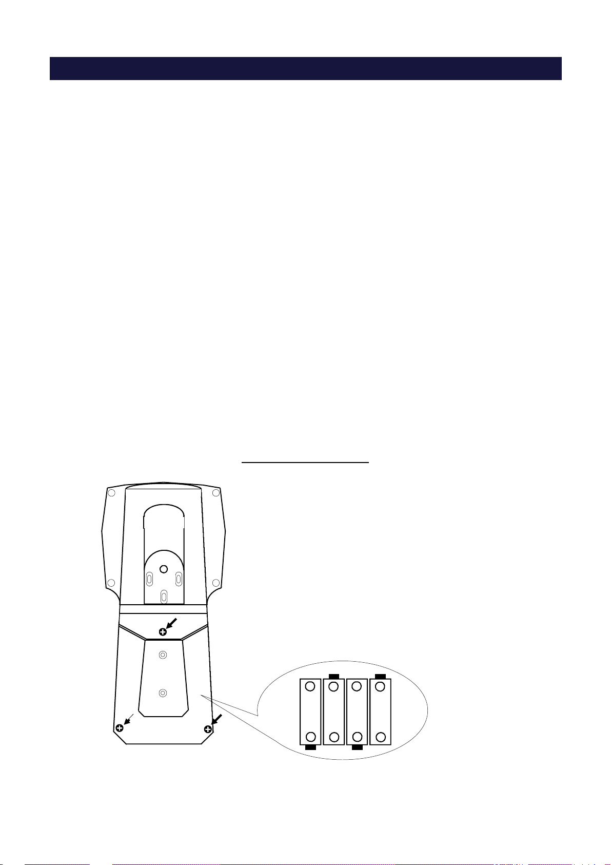
Side “A”
BATTERY REPLACEMENT
LC TESTER: Rear view
Remove the 3 screws indicated by the arrows
Gently raise side A of the cover and slide it out.
Replace the 4 batteries as required, observing
polarity as marked on the battery holder
(See figure below).
Reposition the cover in its seat
Replace the 3 screws
+
-
-
+
-
+
+
-
The manufacturer waives all responsibility for any damage to the Load Cell Tester
caused by the use of batteries other than those listed above.
4
Page 5
MAIN PERFORMANCES
Even if the 2 main functions performed by the Load Cell Tester are independent, they
allow to carry out the complete analysis of any weighing system composed by load cells (up
to 4) and weight indicator.
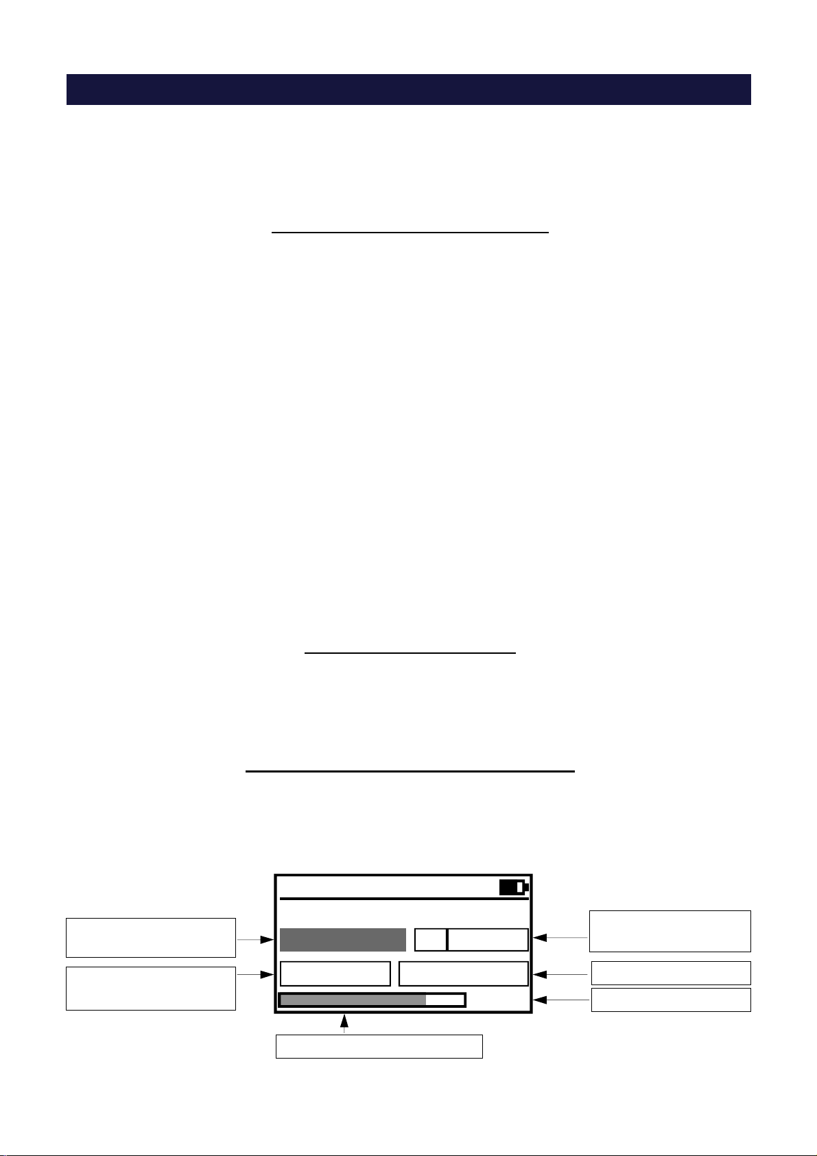
This mode is used to diagnosis the load cells.
The display shows the following group of parameters:
1. The signals coming from the load cells (mV/V values)
2. The distribution of the weight on the load cells (% values)
3. Load on each load cell compared with its nominal capacity (% values)
4. Weight value on each load cell (expressed in the selected measurement unit: g, kg,
Ton, lb, N, kN)
Values 3 and 4 are only displayed if the parameters described on pages 15 to 17 have been
programmed.
Faulty load cells or bad connections*, zero offset drifts or unstable signals can be easily
detected.
* These messages appear on the display in the following conditions:
1. “EXC +” indicates a problem with the + Excitation lead
2. “EXC -” indicates a problem with the - Excitation lead
3. “SIGNAL” indicates a problem with one of the Signal leads
The 1006 Tester in this operating mode allows to view the peak values of each load cell.
The peak value cab be enabled or disabled, for all the 4 groups of parameters above
described by pressing long the key 5. To erase peak values detected, press key C.
In this mode the load cell tester is used to calibrate or check out the weight indicator.
A signal of up to 20 mV can be generated and used to check the linearity and to check or
calibrate the Zero and Span of any weighing instrument.
Function for testing the load cells
Load Cells Peak Function
Transducer Simulator / Calibrator Mode
mV/V signal to instrument
Excitation from instrument
Transducer Simulator
Output Signal
+ 1.600 mV/V
V in +4.95
mV/V bar-graph (0 - 100%)
GW 800 kg
5
+ 7.920 mV
+ 80%
mV signal to instrument
Weight value
% of output signal
Page 6
SWITCHING BETWEEN “LOAD CELL TESTER” AND “CALIBRATOR” MODES
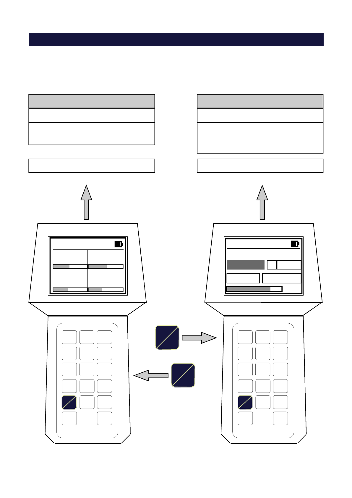
Switching between the 2 functions (as described on the previous page) is performed by
pressing the Test/Cal key:
Function
LOAD CELL TESTER
To be used exclusively for testing
the load cells
Operating mode described on page 14
mV/V Input Signals
1 2
1.024 1.131
Function
CALIBRATOR/SIMULATOR
To be used exclusively for testing
and calibrating the weighing
instrument.
Oper. mode described on page 21, 22
Transducer Simulator
Output Signal
mV/V
+ 1.600
mV
+ 7.920
3 4
0.978 0.856
Test
Cal
Test
Cal
Test
Cal
V in +4.95
Test
Cal
GW 800 kg
+80%
6
Page 7

CONNECTION TO THE LOAD CELLS with Cable “A”
Cable “A”, terminates with a 25 pin female Sub-D connector and is supplied with the J1/PT Screw
Terminal Board.
Connection using Cable “A” to CGS4/C junction Board
CGs
Cella 1
Cella 2
LC’s Tester side
Cella 3
Cella 4
If the existing installation is equipped with model CGS4/C or model CEM4/C summing junction
board, only connect Cable “A” directly to the 25 pin Sub-D connector on the board, without using
the J1/PT Board.
Connection using Cable “A” to CGS4/C
CGS4/C
L.C. 1
LC’s Tester side
L.C. 4
Connection using Cable “A” to CEM4/C
LC’s Tester side
L.C. 2
L.C. 3
CEM4/C
L.C. 1
L.C. 2
L.C. 3
L.C. 4
7
Page 8
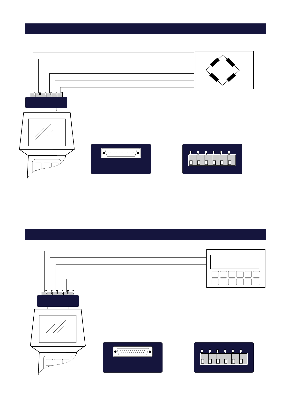
USING THE LOAD CELL TESTER IN “CALIBRATOR” MODE WITH J1/CB
+ Segnale
- Segnale
- Sense
+ Sense
+ Alimentazione
- Alimentazione
Load cell to be
checked
The card J1/CB board, supplied with the cable "B", provided allows
the use of the tester for checking the load cell.
See above illustration for wiring connections
INSTRUMENT SIDE
LC TESTER SIDE
-Exc +Exc +Sns -Sns -Sig +Sig
USING THE LOAD CELL TESTER IN “CALIBRATOR” MODE WITH J2/CB BOARD
+ Signal
- Signal
- Sense
+ Sense
+ Excitation
- Excitation
888888
Instrument to be
calibrated
The J2/CB Calibration Board, supplied with cable “B”, provides another
method of connecting to the weight indicator when using the load cell
tester in “Calibrator” mode. See above illustration for wiring connections.
INSTRUMENT SIDE
LC TESTER SIDE
8
-Exc +Exc +Sns -Sns -Sig +Sig
Page 9
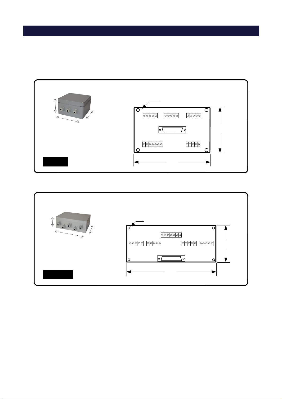
CGS4/C and CEM4/C SUMMING JUNCTION BOXES
The CGS4/C and CEM4/C summing junction boxes, are equipped with a 25 pin
Sub-D connector, which provides a quick reliable connection to the Model 1006
LC System Tester with standard Cable “A”.
90
160
Box Dimensions
(mm)
CGS4/C
90
200
Ø 6,5
160
(mm)
87
Board Dimensions
146
Board Dimensions
Ø 5
150
(mm)
70
Box Dimensions
(mm)
CEM4/C
170
In order to use the LC System Tester on weighing systems using summing
J-boxes other than the CGS4/C or CEM4/C, we are offering our customers
a free evaluation for installing a 25 pin Sub-D connector on their own summing
junction boards.
If you would like to take advantage of this offer, we would require detailed
drawings or a sample of the summing J-Boxes that you are currently using.
9
Page 10

KEY FUNCTIONS IN OPERATING MODE
3
Test
Cal
Switch
view
Enter
0
Display intensity adjustment (see page 20)
Switching between LOAD CELL TESTER and CALIBRATOR modes
Navigating through the various display views in LOAD CELL TESTER mode (see page 14)
Access to configuration menu
Short press: access to “WEIGHING PARAMETERS” (see page 15)
Long press: access to “ SETUP MENU” (see page 17)
Zero the weight value in CALIBRATOR mode (see page 21)
C .
2
8
+
Erase the zero of the weight value in CALIBRATOR mode (see page 21)
Coarse increment (in 0.1 mV/V steps) of the output signal in CALIBRATOR mode (see page 21)
Coarse decrement (in 0.1 mV/V steps) of the output signal in CALIBRATOR mode (see page 21)
Fine increment of the mV/V output signal in CALIBRATOR mode (see page 21)
Fine decrement of the mV/V output signal in CALIBRATOR mode (see page 21)
Switch-off
10
Page 11

2
+
8
KEY FUNCTIONS WITHIN THE VARIOUS MENUS
Data Selection (from a list)
They take meaning of “Arrow up” and “Arrow down”.
They allow to select the previous/next parameter from a list of parameters proposed by
the instrument
Sometimes the selection of a certain parameter is performed with these keys instead of
with the Arrow up/down keys.
The symbols + and — appear on the display to inform the Operator.
6
4
Enter
……
Takes meaning of “Arrow right”.
Allows to access the parameter previously selected with Arrow up/down keys.
Takes meaning of “Arrow left”.
Exits the menu without saving the changes
Exits the menu after saving the changes
Entering Numerical Data
9 0
Keys 0 to 9 are used to program all those parameters requiring numerical
values, such as the load cell capacity, etc.
C .
Enter
This key performs 2 functions:
1. Used to insert a decimal point in numerical values.
2. Used to erase the data: Press momentarily to erase the last digit
Press slightly longer to erase all of the data
Confirm and quit the settings.
11
Page 12
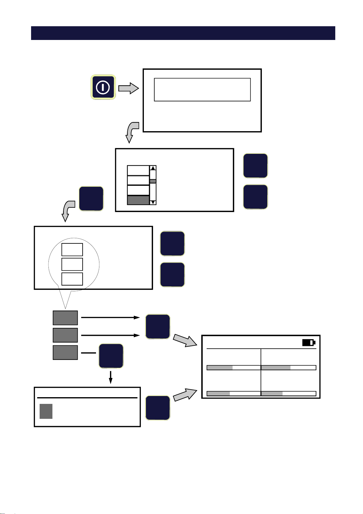
POWER-ON SEQUENCE
When powering-on the LC Tester the following parameters must be programmed:
Number of load cells - Load cells Impedance.
Power-ON:
Confirm
LC’s impedance
350
700
Enter
Ω
Ω
Ω
Enter
Confirm
LC System Tester
Firmware: PMT401
Number of Load Cells
1
2
3
4
Enter
2
8
Rev. 1.3
2
Select
Confirm
Selection
8
The value can be selected
between 350 and 700Ω, otherwise
it can be programmed by
choosing the empty box in the
lower part of the display.
Once the value has been set, the
LC Tester enters the Operating
Mode automatically.
The firmware code and
the release number
appear on the display
for about 3 seconds:
Selection
350
Enter
700
Impedance value
1
2
3
Min. programmable value: 300Ω
Max. programmable value: 4500Ω
Decimal values will be automatically rounded
to the lower integer value.
Enter
1000
Enter
Operating Mode
mV/V Input signals
1 2
3 4
1.024 1.131
0.978 0.856
NOTE:
In case the last switch-off of the LC Tester was caused
by the Auto Shut Off function (see page 18), the LC
Tester immediately resumes the Operating
Mode,without asking for the LC’s Number and
Impedance to be programmed.
The instrument’s memory will keep the stored values.
12
Page 13

OPERATING MODE : DATA VISUALIZATION
During normal operation in Load Cell Tester mode (see page 6), the “SWITCH VIEW” key switches the display
among 4 different views.
1
mV/V Input Signals
1 2
3 4
Individual mV/V values coming from the
load cells
Switch
view
Weight Values
1 2
3 4
128.0 141.5
4
123.0 107.5
Weight value on each load cell. Expressed
in the selected unit of measurement.
1.024 1.131
0.978 0.856
Weight Distribution
1 2
3 4
Distribution of the weight on the load cells
Ideal distribution: 25% each LC
Switch
view
2
25.6 % 28.3 %
24.6 % 21.5 %
Switch
view
3
Switch
view
NOTE: Display views 3 (% of load on LC’s) and 4 (Weight values) give significant values only if the load cell single
capacity and sensitivities have been programmed.
% of load on LC’s
1 2
3 4
51.2 % 56.6 %
49.2 % 43.0 %
Load on each load cell compared to its
nominal capacity
13
Page 14
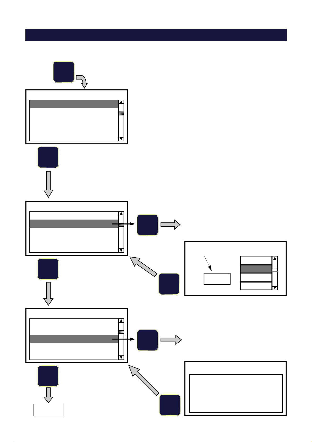
In Operating Mode:
“WEIGHING PARAMETERS” MENU
Press
8
Enter
WEIGHING PARAMETERS
Number of Load Cells
Unit of Measurement
Load Cell Capacity
LC Sensitivity Values
Display Division Value
WEIGHING PARAMETERS
Number of Load Cells
Unit of Measurement
Load Cell Capacity
LC Sensitivity Values
Display Division Value
6
Measurement unit selection, with and .
The selected unit of measurement appears
in the box on the left of the screen.
Unit of Measurement
8
WEIGHING PARAMETERS
Number of Load Cells
Unit of Measurement
Load Cell Capacity
LC Sensitivity Values
Display Division Value
8
Page 16
6
Enter
Enter
g
kg
kg
Enter the nominal capacity of a single load
cell.
The instrument automatically multiplies
the single load cell capacity by the
“Number of LC’s” being used.
Load Cell Capacity
Enter capacity
of a single LC
Ton
lb
250 kg
14
Page 15
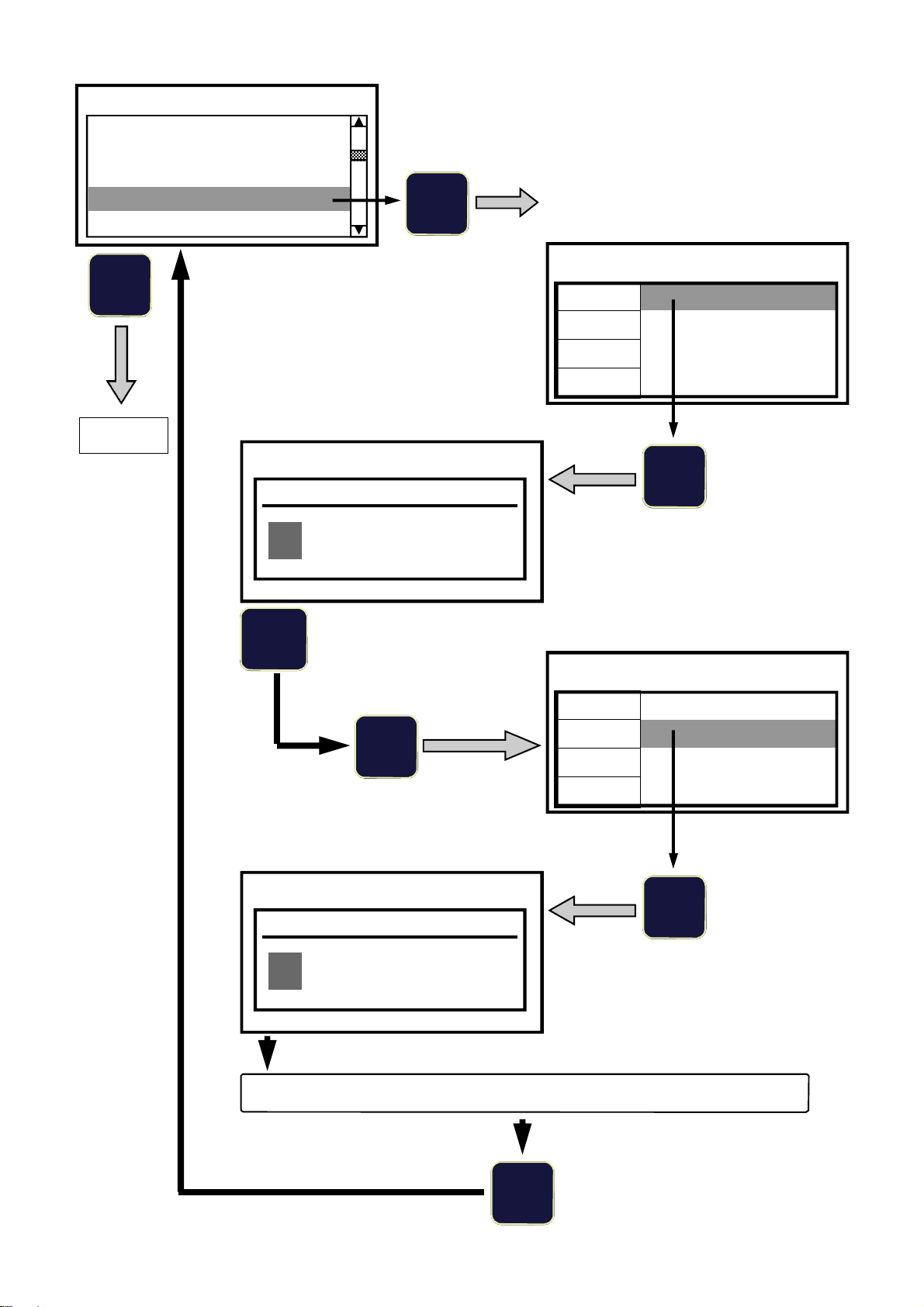
WEIGHING PARAMETERS
Unit of Measurement
LC Sensitivity Values
Display Division Value
8
Page 17
Number of LC’s
Load Cell capacity
L.C. 1 mV/V
6
LC Sensitivity Values
1
2
3
2.0108
Setting the nominal sensitivity (in mV/V)
of each single load cell.
Take the data from the calibration
certificates or from the labels sticked on
the load cells.
LC Sensitivity Values
L.C. 1
L.C. 2
L.C. 3
L.C. 4
2.0000 mV/V
2.0000 mV/V
2.0000 mV/V
2.0000 mV/V
6
Setting the nominal sensitivity of
LC 1
Enter
8
LC Sensitivity Values
L.C. 2 mV/V
1
2
3
2.0067
LC Sensitivity Values
L.C. 1
L.C. 2
L.C. 3
L.C. 4
2.0108 mV/V
2.0000 mV/V
2.0000 mV/V
2.0000 mV/V
6
Setting the nominal sensitivity of
LC 2
Perform the same procedure for the remaining load cells
4
15
Page 16
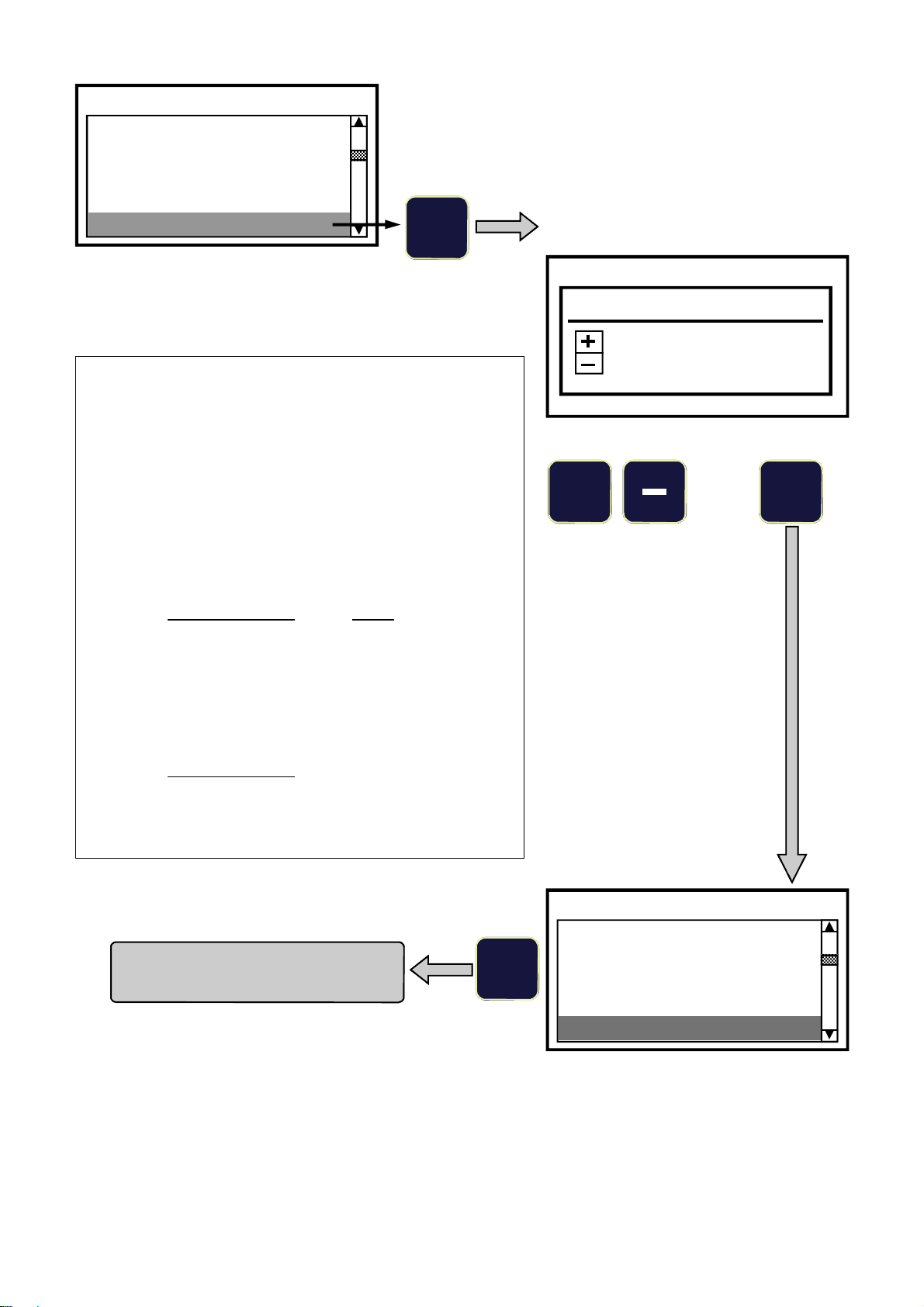
WEIGHING PARAMETERS
Number of LC’s
Unit of Measurement
Load Cell Capacity
LC Sensitivity Values
Display Division Value
6
Selection of the Display division value
Display Division Value
The Display division value can be selected from a list (0.001 to
100, expressed in the measurement unit previously enabled).
The LC Tester automatically offers a value optimised to 10000
counts, based on the nominal capacity of the load cells (sum
of the load cell’s single capacities).
Example: Single LC capacity = 250
Number of load cells = 4
LC’s Total capacity (250 x 4) = 1000
The Display division value automatically offered by the LC
Tester will be: 0.1 given by the ratio:
LC’s Total capacity _1000_
10000 10000
However the User has the chance to modify this value (+ or -),
bearing in mind that the maximum number of counts can
be 50000.
Considering the example given here above, the ratio:
LC’s Total capacity
50000
equals 0.02.
This will be the minimum usable Display division value.
= 0.1
0.1
Selection Confirm
+
Enter
Exits the menu and returns
to Operating Mode
16
4
WEIGHING PARAMETERS
Number of LC’s
Unit of Measurement
Load Cell Capacity
LC Sensitivity Values
Display Division Value
Page 17
In Operating Mode:
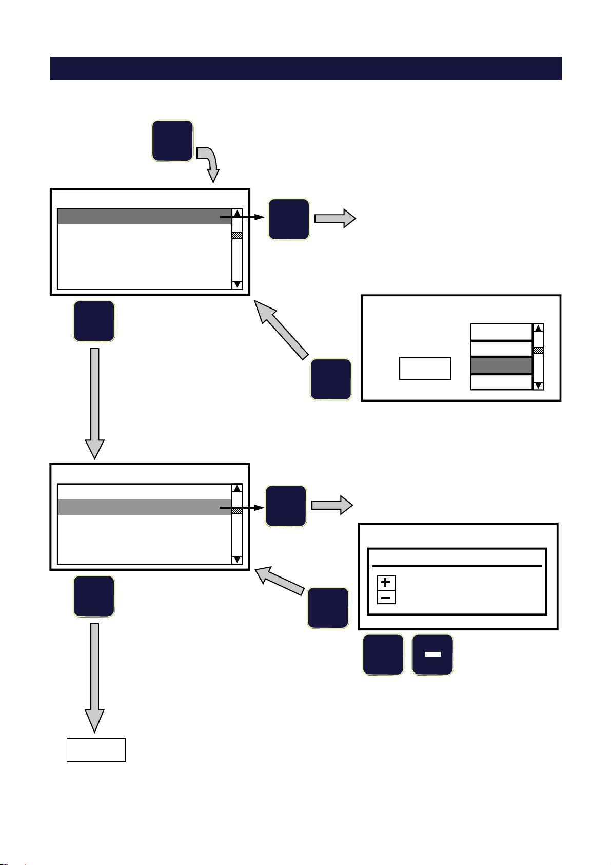
ADDITIONAL FUNCTIONS
Press
and hold
SETUP MENU
Auto Shut Off
LCD Contrast
Set Date (MM/DD/YYYY)
Set Time
Baud Rate
Enter
8
6
Enter
Automatic shut off time delay selection.
The selected value appears in the box on
the left of the screen.
The LC Tester switches off automatically if
no keys are pressed within the selected
time delay.
The countdown is restored if any of the
keys is pressed within the selected time
delay.
“OFF” = function disabled.
Auto Shut Off
OFF
3 MIN
5 MIN
5 MIN
10 MIN
SETUP MENU
Auto Shut Off
LCD Contrast
Set Date (MM/DD/YYYY)
Set Time
Baud Rate
8
Page 19
6
Enter
LCD contrast adjustment.
SETUP MENU
LCD Contrast
+
Adjustment
575
17
Page 18
SETUP MENU
Auto Shut Off
LCD Contrast
Set Date (MM/DD/YYYY)
Set Time
Baud Rate
8
SETUP MENU
Auto Shut Off
LCD Contrast
Set Date (MM/DD/YYYY)
Set Time
Baud Rate
6
6
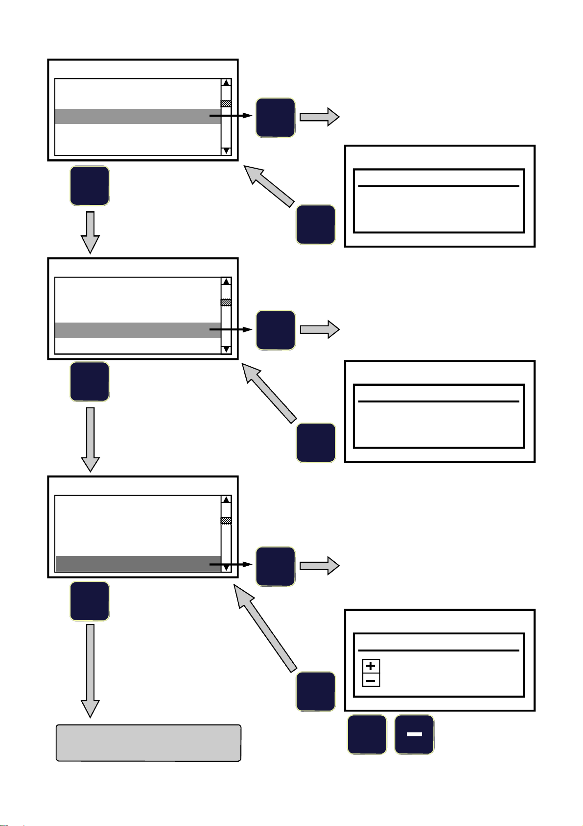
Setting the Date
Max. values: 12 (month)
31 (day)
2050 (year)
SETUP MENU
Set Date (MM/DD/YYYY)
09/20/2006
Enter
Setting the Time
Max. values: 23 (hour)
59 (minutes)
8
SETUP MENU
Auto Shut Off
Set Date (MM/DD/YYYY)
Set Time
LCD Contrast
Baud Rate
4
6
SETUP MENU
Set Time
16:45
Enter
RS-232 baud rate selection.
List of values:
1200 - 2400 - 4800 - 9600 - 19200 -
38400 - 57600
SETUP MENU
RS-232 Baud Rate
Exits the menu and returns
to Operating Mode
18
Enter
+
9600
Selection
Page 19
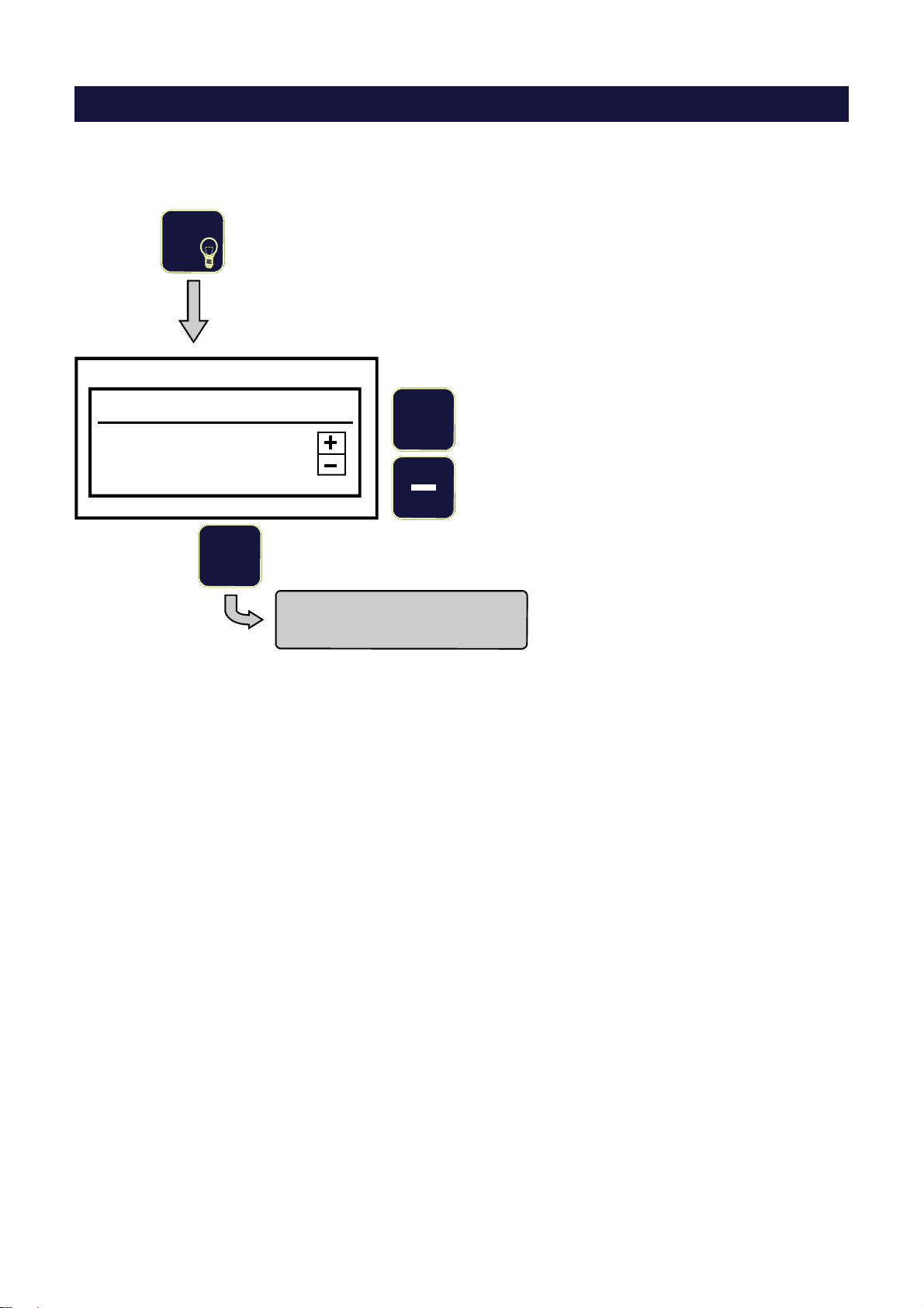
In Operating Mode:
DISPLAY INTENSITY ADJUSTMENT
Press
+ / - keys to adjust
key to exit
3
Display Intensity
4
+
5
Confirm and return to
Operating Mode
Increases Intensity
Reduces Intensity
19
Page 20
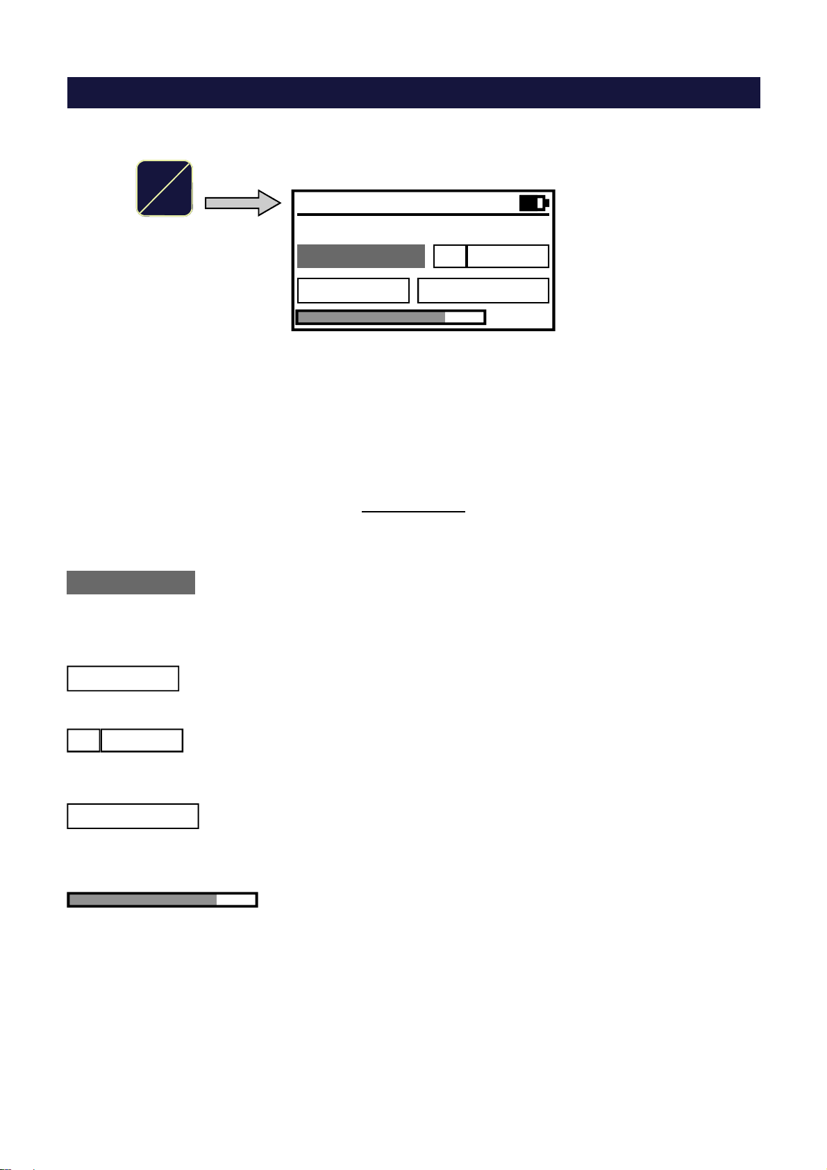
How to enable the function:
Test
Press
Cal
THE “CALIBRATOR” FUNCTION
Transducer Simulator
Output Signal
+ 1.600 mV/V
V in +4.95
Through this function the LC Tester acts as a mV generator, therefore it can be used as a load cell simulator
and/or calibrator for electronic weighing instruments, to check linearity, to check 0 and FS, to perform 0 and FS
calibration.
Refer to page 9 for wiring.
Displayed data
mV/V signal generated by the LC Tester and sent to the instrument.
+ 1.600 mV/V
The and keys allow to generate the signal output (in steps of 0.1 mV/V) over a
range from 0 to FS.
The mV/V Full Scale value corresponds to the average of the individual mV/V load cell
sensitivities programmed in the “WEIGHING PARAMETERS” menu. See page 16.
GW 800 kg
+ 7.920 mV
+ 80%
V in +4.95
+ 7.920 mV
PL 900 kg
In order for the “CALIBRATOR” function to work correctly, the following parameters
“Number of LC’s”, “LC’s sensitivity” and “Single LC capacity” programmed in the LC Tester
must be the same as those programmed in the instrument to be controlled.
Example:
If the instrument to be controlled is normally connected to 4 load cells 250 kg each, 2 mV/V,
the LC Tester must have been programmed with the same data (see pages 15-17):
Number of LC’s = 4 - LC’s sensitivity = 2.0000 - Single LC capacity = 250.
Load cells excitation voltage coming from the instrumentation.
mV signal generated by the LC Tester and sent to the instrument.
This value is the product of “mV/V” multiplied by “Vin”.
Weight value corresponding to the mV/V signal generated by the LC Tester.
The weight value is expressed in the preselected measurement unit and its Full Scale is
the product of “Single LC capacity” multiplied by “Number of LC’s”, programmed in the
“WEIGHING PARAMETERS” menu.
+ 80%
Percentage of signal output referred to the Full Scale.
20
Page 21
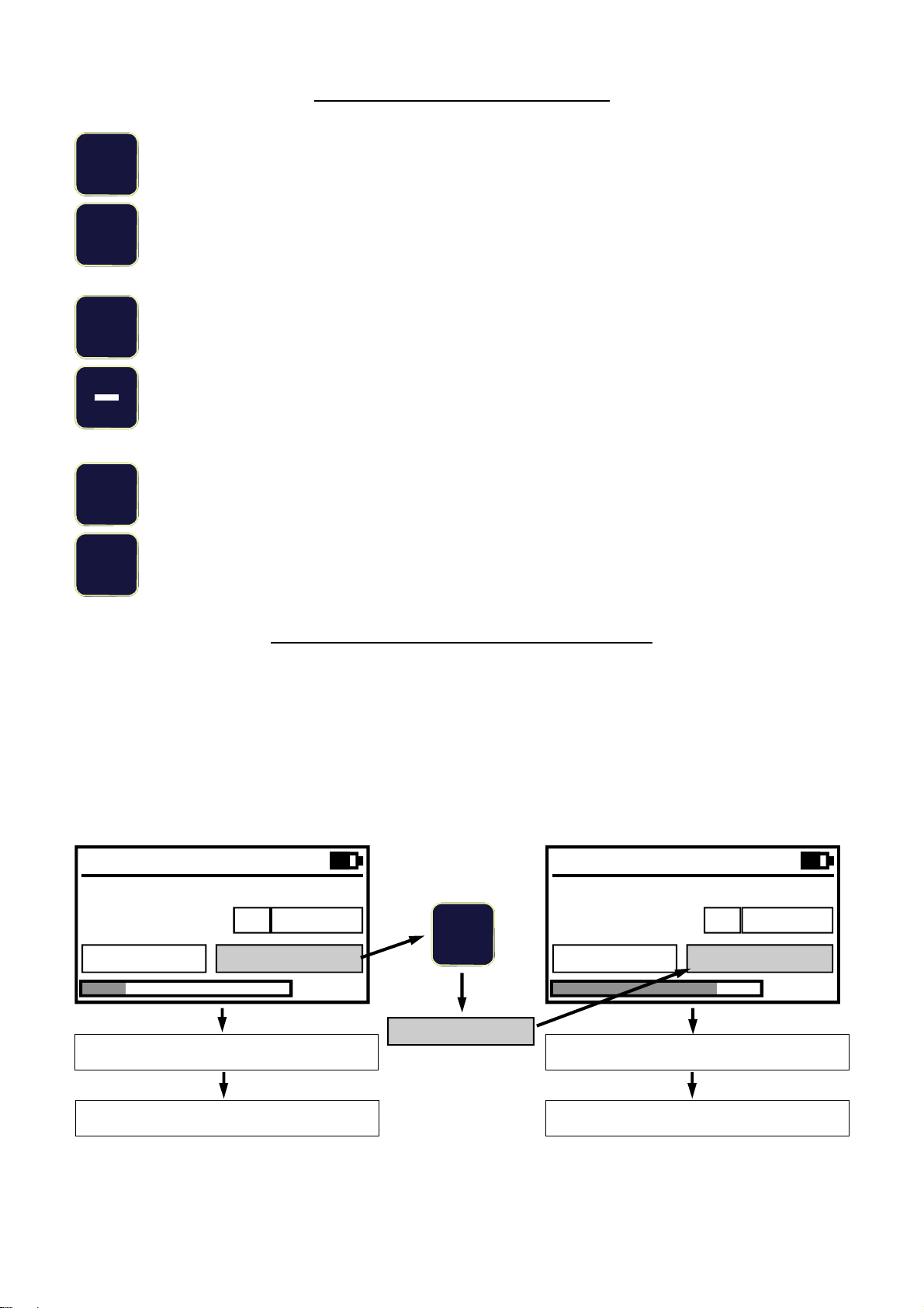
Key functions in “CALIBRATOR” mode
2
8
+
0
C .
Coarse increment of the mV signal output. Each step = 0.1 mV/V.
Range from 0 to F.S.
Coarse decrement of the mV signal output. Each step = 0.1 mV/V.
Range from 0 to F.S.
Fine increment of the mV signal output.
Fine decrement of the mV signal output.
Set to 0 the weight value
Erases the weight value 0 setting
Zeroing the weight value shown on the LC Tester
This function helps the User during the zero and full scale calibration of the weighing instrumentation.
After having performed the zero calibration on the instrument, the user can set to zero the weight value
displayed by the LC Tester also, so that the weight values displayed by the two devices can match.
Example: weighing system comprised of an instrument connected to 4 load cells 250 kg each - 2 mV/V (total
1000 kg), dead load = 200 kg, live weight = 600 kg.
The 0 calibration must be performed with a signal of 0,4 mV/V (equivalent to 200 kg), while the F.S. calibration
must be performed with a signal of 1.6 mV/V (equivalent to a signal increment of 1.2 mV/V = 600 kg)
Transducer Simulator
Output Signal
+ 0.400 mV/V
V in +4.95
0 calibration on the instrument
GW 200 kg
+ 1.980 mV
+ 20%
Press
0
NW 0 kg
Transducer Simulator
Output Signal
+ 1.600 mV/V
V in +4.95
F.S. calibration on the instrument
NW 600 kg
+ 7.920 mV
+ 80%
Weight reading = 0
Note: When the “0” key is pressed the box containing the weight value switches from GW to NW.
Press the “C” key to switch from NW to GW. GW = Gross Weight - NW = Net Weight.
21
Weight reading = 600
Page 22
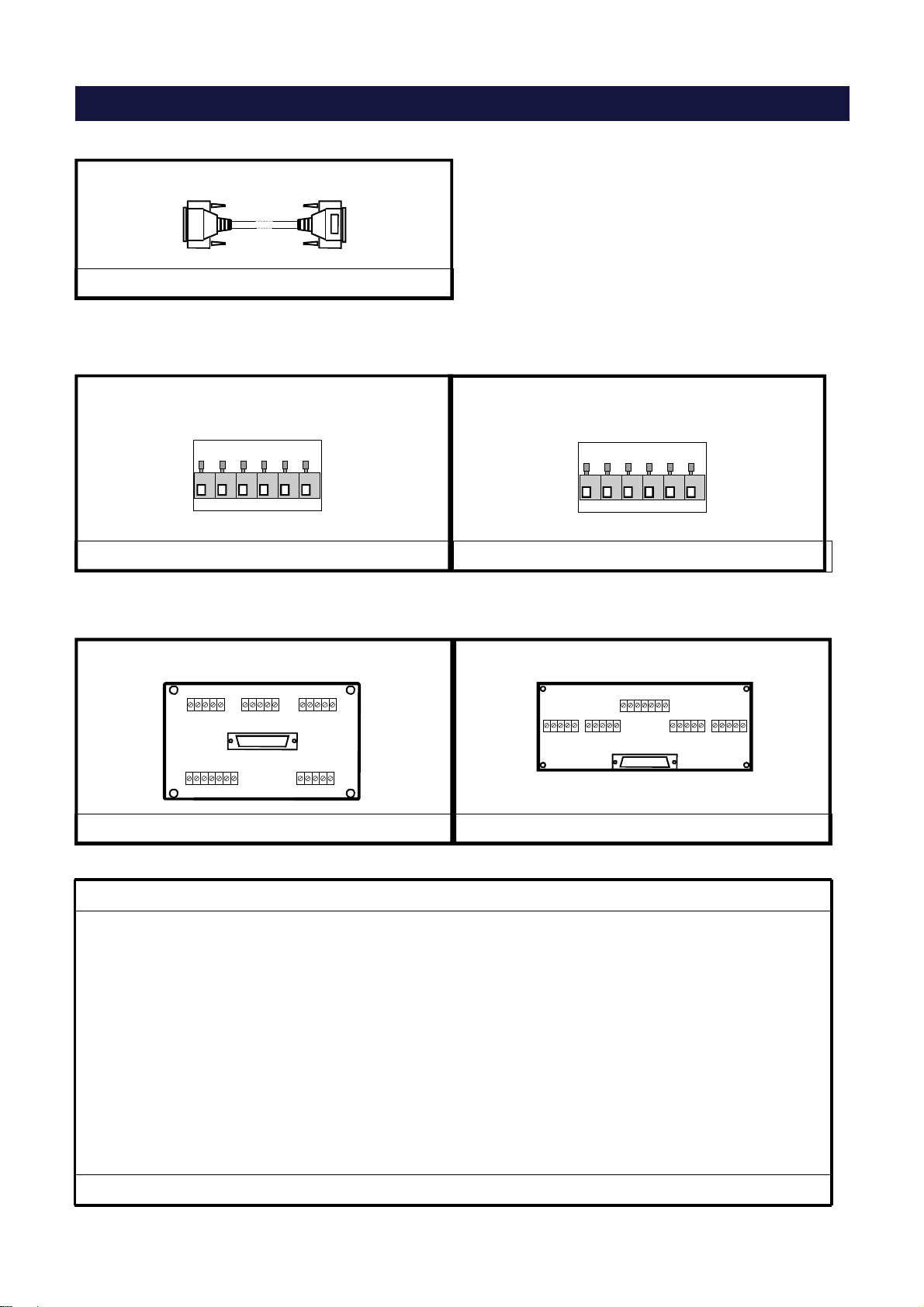
ACCESSORIES, OPTIONS AND SPARE PARTS
Cable “A” 2m long with two 25-pin connectors
Product Code: 1006/A
Spring Terminal load cell board
Model J1/CB
Spring Terminal Calibration Board
Model J2/CB
Product Code: 1006/CB1 Product Code: 1006/CB2
Summing Junction Box - Model CGS4/C Summing Junction Box - Model CEM4/C
Product Code: 1006/CGS Product Code: 1006/CEM
Software program for saving the Configuration Files
It is also possible to save the all weighing parameters for up to 10 different systems.
This file configuration can be strored directly inside on the LC tester and than transferred to the PC via the
RS-232 serial port.
All of the data (number of load cells, capacity, sensitivity, unit of measurement, division value) can be stored
in up to 100 different files which can be recalled when needed. This feature expedites load cell tester set-up
time by eliminating the need of having to re-enter all of the parameters.
It is also possible to save the zero and f/s mV/V values for each system for ease of any periodical checking.
The configuration files can be set and stored directly from the instrument’s keyboard, or with an Excel chart
which can be created on a PC and then transferred to the LC Tester via the RS-232 serial port.
The bi-directional communication feature allows transferring the files from the load cell tester to a computer.
Product Code: 1006/SW
22
Page 23

APPENDIX “A”
UPLOAD/DOWNLOAD FILE SET UP
The following part of the manual describes the function of set up file upload and download of our
weighing instruments model MC 302, DAT 400/500 and MC 352.
For a general description of these functions refer to the next page "File Management Tools"
23
Page 24

FILE MANAGEMENT TOOLS
The LC Tester 1006 allows to do the upload/download of the parameters/calibration set up of the following
instruments: model MC 302, DAT 400/500 and MC 352 ( max 8 file downloading on LC Tester 1006 ).
The management file is made of the functions Receive, Send, and Reset File.
The LC Tester 1006 guarantees the download of the complete configuration of the indicator and can send it to
a PC for storage.
By the bidirectional RS232 communication the same files can be transferred from PC to Tester 1006 and then
to the indicator.
The LC Tester 1006 can immediately send the complete configuration to a new instrument.
The instrument, that received the configuration, is ready to be used on the plant.
24
Page 25
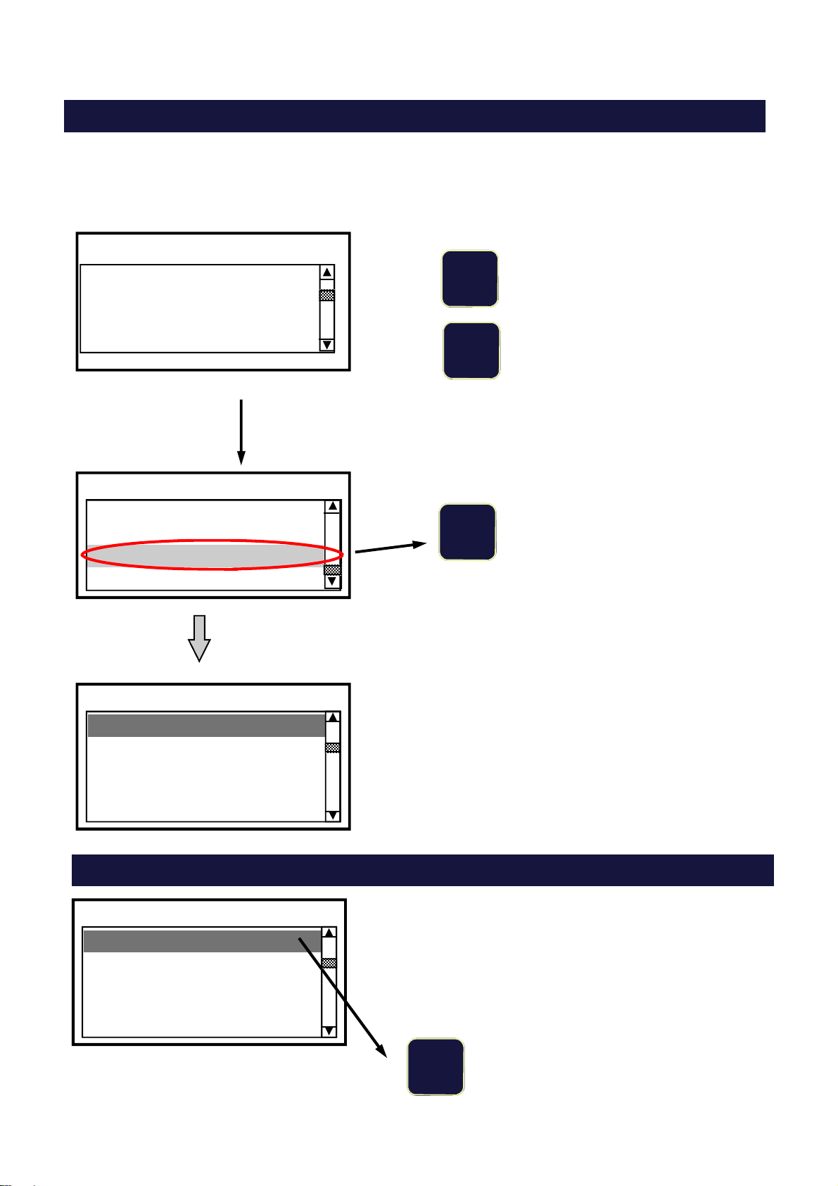
FILE MANAGEMENT MENU
Access to the menu by pressing DATA WEIGHING release the ENTER button and then scrolling
through the menus with the arrow keys up / down.
So the final part of the menu "DATA WEIGHING" will be presented as follows:
WEIGHING DATAS
Number of Load Cells
Unit of Measurement
Load Cell Capacity
LC Sensitivity Values
2
8
Use the up/down ARROW keys to
select the “Configuration Files” ,
WEIGHING DATAS
LC Sensitivity Values
Display Division Value
Instrument Files
Configuration Files
CONFIGURATION FILE
Receive Instrument File
Send Instrument File
Reset Instrument File
.
CONFIGURATION FILE
Receive Instrument File
Send Instrument File
Reset Instrument File
6
Press the arrow key to access
the selected file.
RECEIVE A FILE
The File Receive Function allows to save the set up of
the indicator directly on Tester 1006 through the following steps:
1. Typing the file name and confirm
6
25
Press the arrow key to access
the selected file.
Page 26
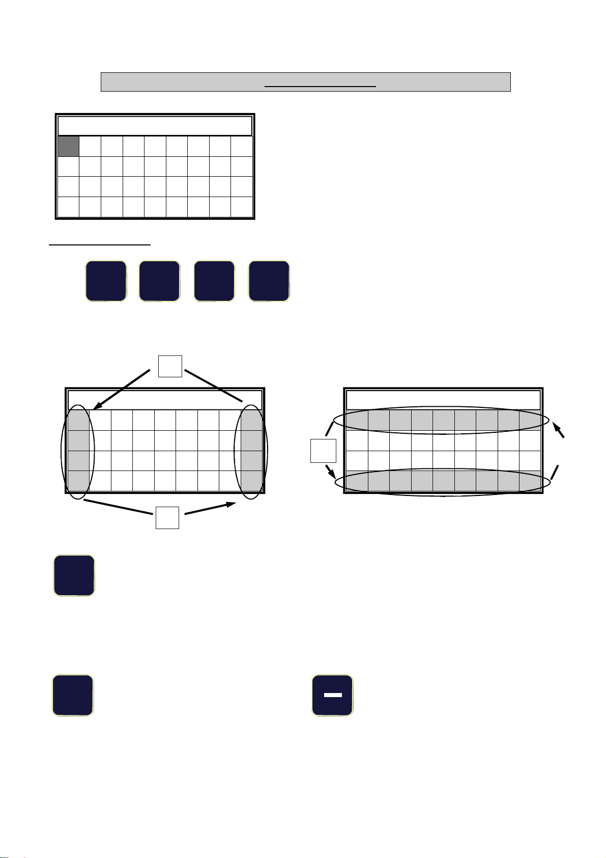
1. TYPING the NAME
NAME:
A B D C E F H G I
J K M L N O Q P R
S T V U W X Z Y 0
1 2 4 3 5 6 8 7 9
Entering the file name:
The following grid appears on the display.
The letter “A” is highlighted.
After creating the file name press the enter
key to transfer the file on LC Tester 1006.
KEY FUNCTIONS
2
The keys allow to move the cursor to any direction and also to pass from one to the other side of the grid
without the need to scroll all the characters of the line /column, see the pictures here below:
8
4
6
NAME: CFG13
B D C E F H G I A
NAME: CFG13
A B D C E F H G I
J K M L N O Q P R
S T V U W X Z Y 0
1 2 4 3 5 6 8 7 9
Enter
C .
-Short pressure: Enters the selected character and allows the selection for the next one.
The character just entered will appear in the “NAME” field.
When the last character (the 8th) is entered the Enter key causes the
storage of all the weighing parameters into the file just created.
-Long pressure: Stores the weighing parameters into a file named with less than 8
characters.
-Press for about 1 second to erase the last
character entered.
-Press for a longer time to erase the entire
name.
J K M L N O Q P R
S T V U W X Z Y 0
1 2 4 3 5 6 8 7 9
Exit the procedure and resume normal
operating mode
No data storage.
N.B. Before the Receiving procedure check that the indicator is the Download configuration mode (sending
configuration), otherwise after a short time the management file is deactivate without saving any files in the
memory. If there is communication between the indicator and the tester and the tester is in Receiving mode it
shows "Please wait". Once the Receiving operation is done the Tester will automatically exit the menu and by
save the file.
26
Page 27
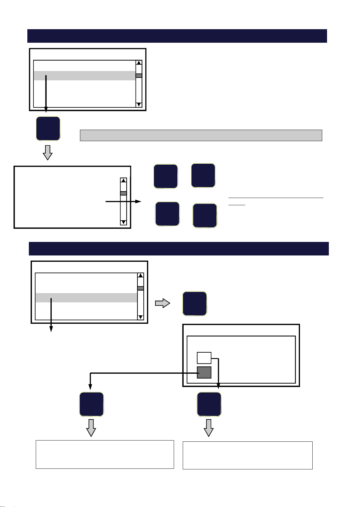
Send a Configuration File to an indicator
CONFIGURATION FILE
Receive Instrument filee
Send Instrument File
Reset Instrument File
6
Existing File List
ABCDEFGH
CFG12
TXKBGFRY
1234ABCD
The Send function is used to update a new instrument
and make it “operative”.
This procedure can be performed as follows:
1. Opening a file from the existing file list
2. Send the file to the instrument
Selection file and send file
Use the keys to highlight the
2
8
“Configuration Files” selection, then
press the arrow
key send file to instrument.
N.B. The indicator will be on upload
mode.
4
6
key exit the menu step by step
until normal operating mode.
CONFIGURATION FILE
Receive Instrument filee
Send Instrument File
Reset Instrument File
Deleting all files
This function allows to erase all set up configuration files
stored on LC tester 1006.
6
Confermi eliminazione File ?
Confirm ?
SI
NO
NO
YES
Enter Enter
CFG13
Enter
Enter
Selezione
Select
Conferma
Confirm
Exit the menu and delete the
selected file and return on
“INSTRUMENT FILE ” menu
Exit the menu without erasing all files
and return on “INSTRUMENT FILE ”
menu
27
Page 28

APPENDIX “B”
CONFIGURATION FILE MANAGEMENT
This section of the manual covers an OPTIONAL function that can only be activated
by purchasing a PASSWORD.
Please contact the Manufacturers Sales Department for Terms and Conditions.
Please refer to page 25 for a general description of the Configuration File
Management option.
28
Page 29
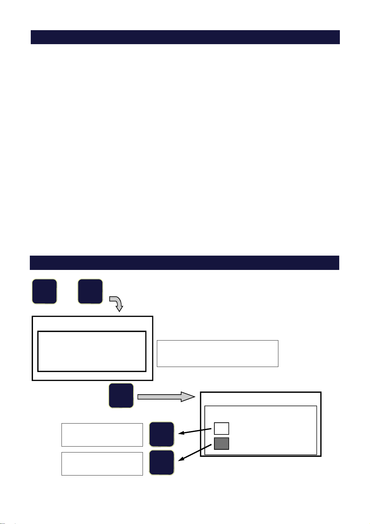
The CONFIGURATION FILE MANAGEMENT
This function enables storage of up to 100 Configuration Files inside of the Load Cell Tester, each File
contains all the weighing parameters for up to 100 different systems.
The Configuration File management is performed using the Save, Open, Delete, Transfer File functions.
Each file is identified by a name consisting of 8 alphanumeric characters.
The Configuration File function expedites load cell tester set-up time by eliminating the need of having to
re-enter all of the parameters.
The following weighing parameters can be stored in each configuration file:
Number of load cells (see page 13)
Load cell nominal capacities (see page 15)
Unit of measurement for the weight values (see page 15)
Individual load cell sensitivities (see page 16)
Display division value (see page 17)
It is also possible to save the zero and f/s mV/V values for each system for ease of any periodic checking.
These stored mV/V values can be generated by the Load Cell Tester when being used as a “Calibrator”, in
order to calibrate the Zero and Full Scale of the instrumentation installed in the weighing system.
The configuration files can be set and stored directly from the instrument’s keyboard, or with an Excel chart
which can be created on a PC and then transferred to the LC Tester via the RS-232 serial port.
The bi-directional communication feature allows transferring the files from the load cell tester to a computer.
Procedure for activating the CONFIGURATION FILES management
1 9
+
Press and hold
CONFIGURATION FILES
Password
0
Enter
Exits the menu without
activating the function
Program the password, then press the
Enter key to confirm
CONFIGURATION FILES
Activate the function ?
Enter
NO
YES
Enter
Select
Confirm
Activates the function
and exits the menu
Enter
29
Page 30
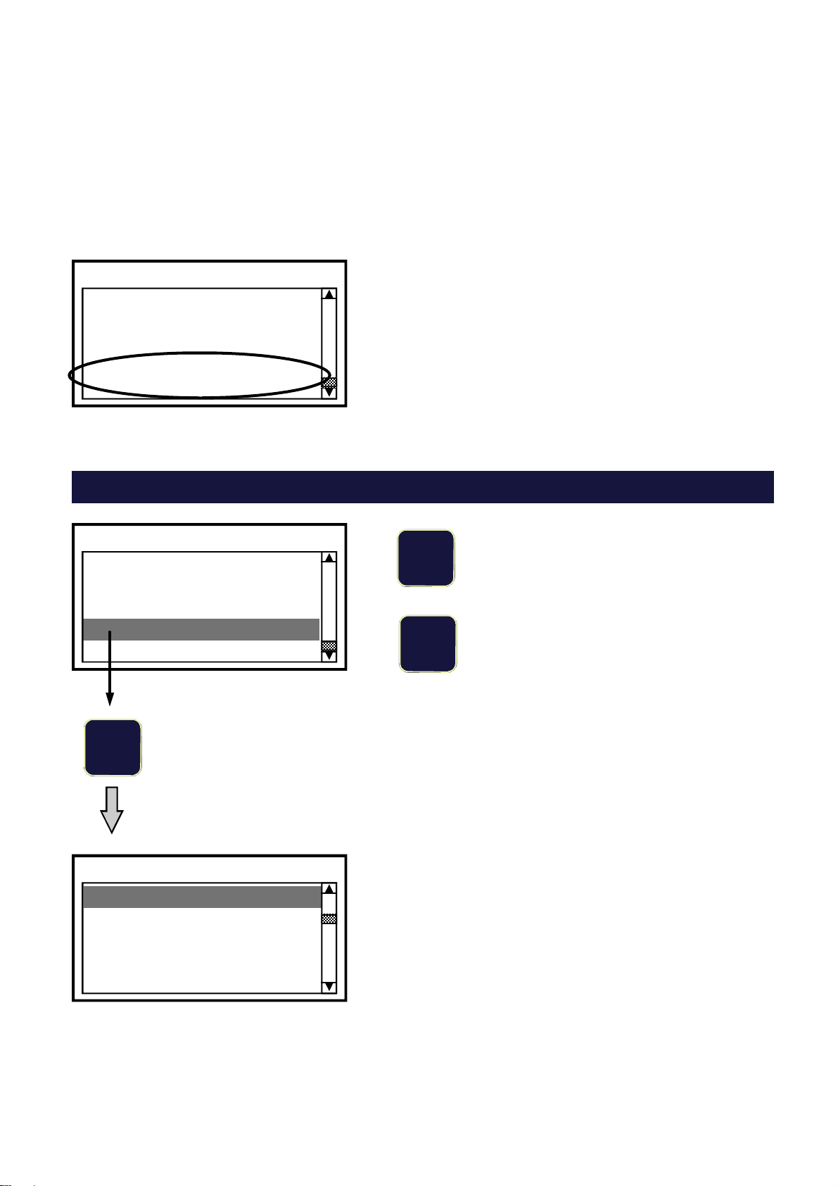
Once the “CONFIGURATION FILES” function has been activated, the following selections are automatically
added to the “WEIGHING PARAMETERS” menu:
Configuration Files
Stored mV/V Signals
Therefore, the last part of the “WEIGHING PARAMETERS” menu will appear as follows:
WEIGHING PARAMETERS NOTE:
Load Cell Capacity
LC Sensitivity Values
Display Division Value
Configuration Files
Stored mV/V Signals
Access to the “WEIGHING PARAMETERS” menu is performed
by pressing the ENTER key, as described on page 15 of this
Manual.
Accessing the CONFIGURATION FILES menu
WEIGHING PARAMETERS
Load Cell Capacity
LC Sensitivity Values
Display Division Value
Configuration Files
Stored mV/V Signals
6
CONFIGURATION FILES
Save
Open
Delete
Send and Receive Files
2
8
Use the arrow up/down keys to highlight the
“Configuration Files” selection, then press
the arrow right to access the menu.
30
Page 31
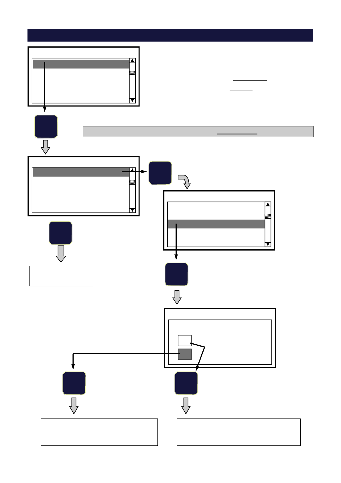
Saving the weighing parameters in a file
CONFIGURATION FILES
Save
Open
Delete
Send and Receive Files
6
Save
Existing File List
Enter File Name
8
The Save function is used to store all the data previously
programmed in the WEIGHING PARAMETERS menu in a file
using one of the following methods:
1. Save the data into an existing file
2. Save the data into a new file
1. Saving data to an existing file
6
Existing File List
ABCDEFGH
CFG12
CFG13
TXKBGFRY
1234ABCD
Next
page
Exits the menu and saves the data.
Normal operating mode is
automatically resumed
The keys scroll UP and DOWN
6
NO
YES
Enter Enter
the list of existing files.
The key access the selected file.
The key quits the menu step by step
until normal operating mode is resumed.
CFG13
Save data in the File ?
Enter
Select
Confirm
Exits the menu without saving the
data.
Display returns to Save menu.
31
Page 32
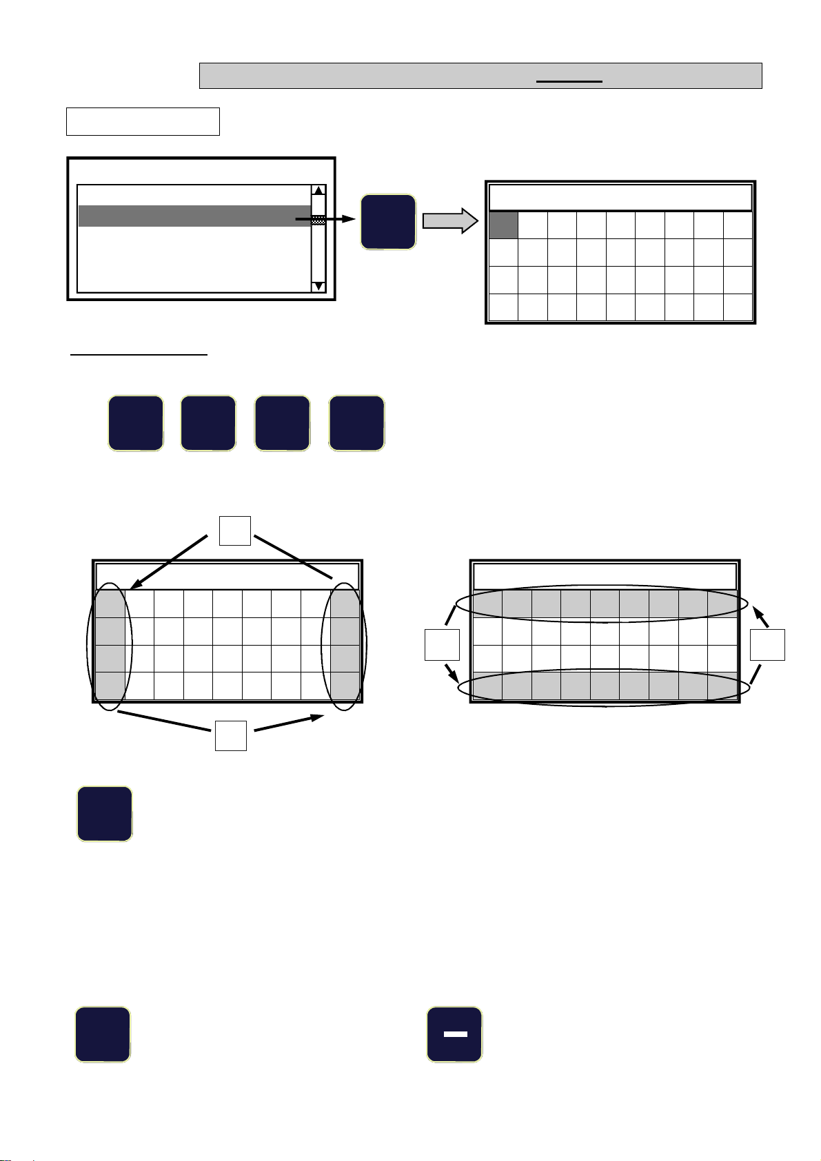
2. Saving data in a new file
From previous page
Save
Existing File List
Enter File name
6
Creating a new file
Entering the file name:
The following grid appears on the display.
The letter “A” is highlighted.
NAME:
A B D C E F H G I
J K M L N O Q P R
S T V U W X Z Y 0
1 2 4 3 5 6 8 7 9
KEY FUNCTIONS
2
The keys allow to move the cursor to any direction and also to pass from one to the other side of the grid
without the need to scroll all the characters of the line /column, see the pictures here below:
8
4
6
NAME: CFG13
B D C E F H G I A
J K M L N O Q P R
S T V U W X Z Y 0
1 2 4 3 5 6 8 7 9
Enter
-Short pressure: Enters the selected character and allows the selection for the next one.
The character just entered will appear in the “NAME” field.
When the last character (the 8th) is entered the Enter key causes the
storage of all the weighing parameters into the file just created.
-Long pressure: Stores the weighing parameters into a file named with less than 8
characters.
Exits the procedure without saving any data if no characters were
previously entered.
Quitting the procedure means to resume normal operating mode.
NAME: CFG13
A B D C E F H G I
J K M L N O Q P R
S T V U W X Z Y 0
1 2 4 3 5 6 8 7 9
C .
-Press for about 1 second to erase the last
character entered.
-Press for a longer time to erase the entire
name.
32
Exits the procedure and resumes normal
operating mode
No data storage.
Page 33
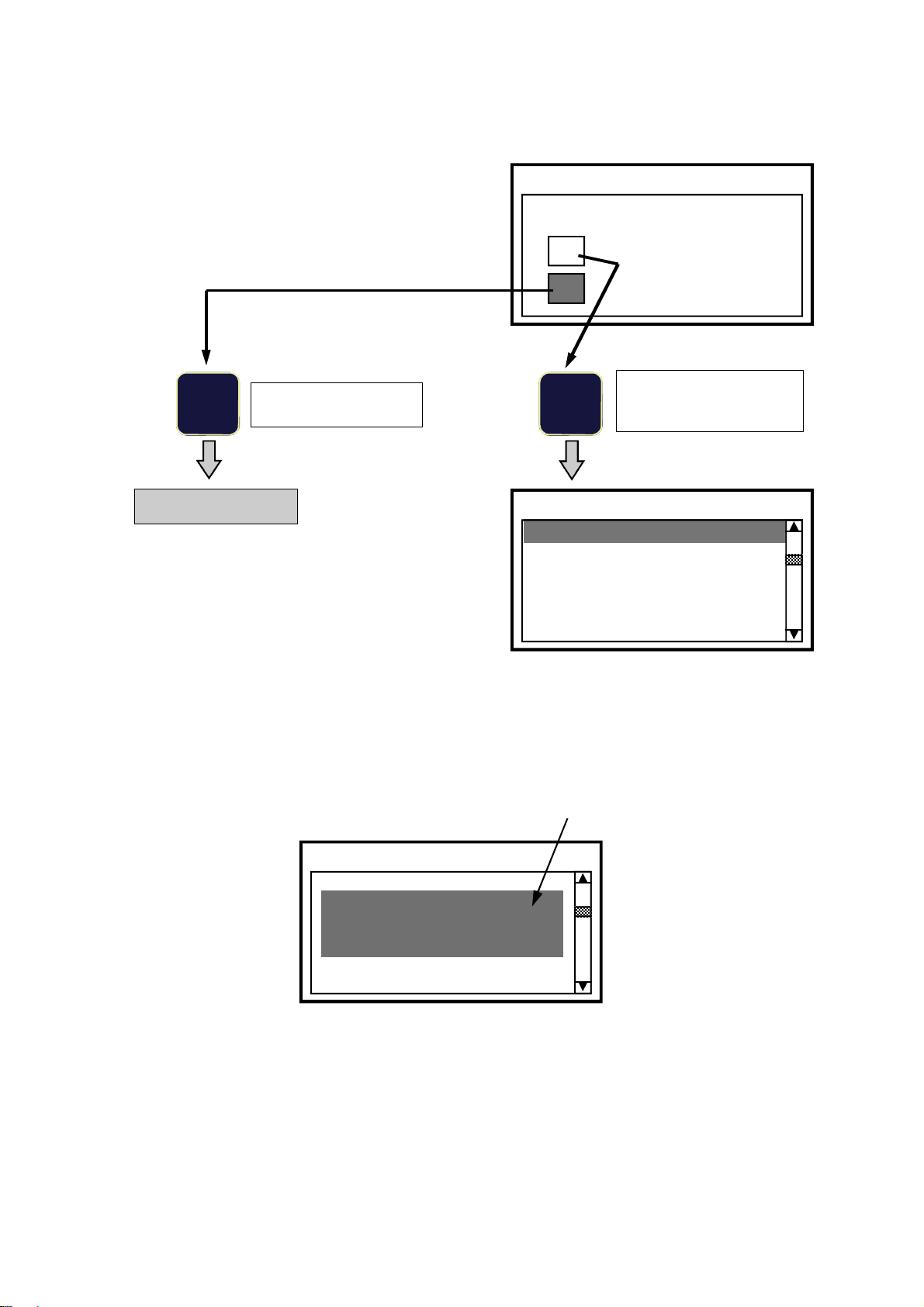
If the new file name matches an existing file name, the following message will appear on the display:
CFG13
Overwrite the File ?
NO
YES
Enter
Select
Confirm
Overwrites the File
and quits the procedure.
Operating Mode
Enter Enter
overwritten.Display
returns to Save menu
Save
Existing File List
Enter File Name
A warning message appears on the display in case the maximum number of files (100) is reached.
(3 secs.)
File is not
Save
Max. number of files
Invia tutti i File
Not enough memory
Ricevi un File
33
Page 34
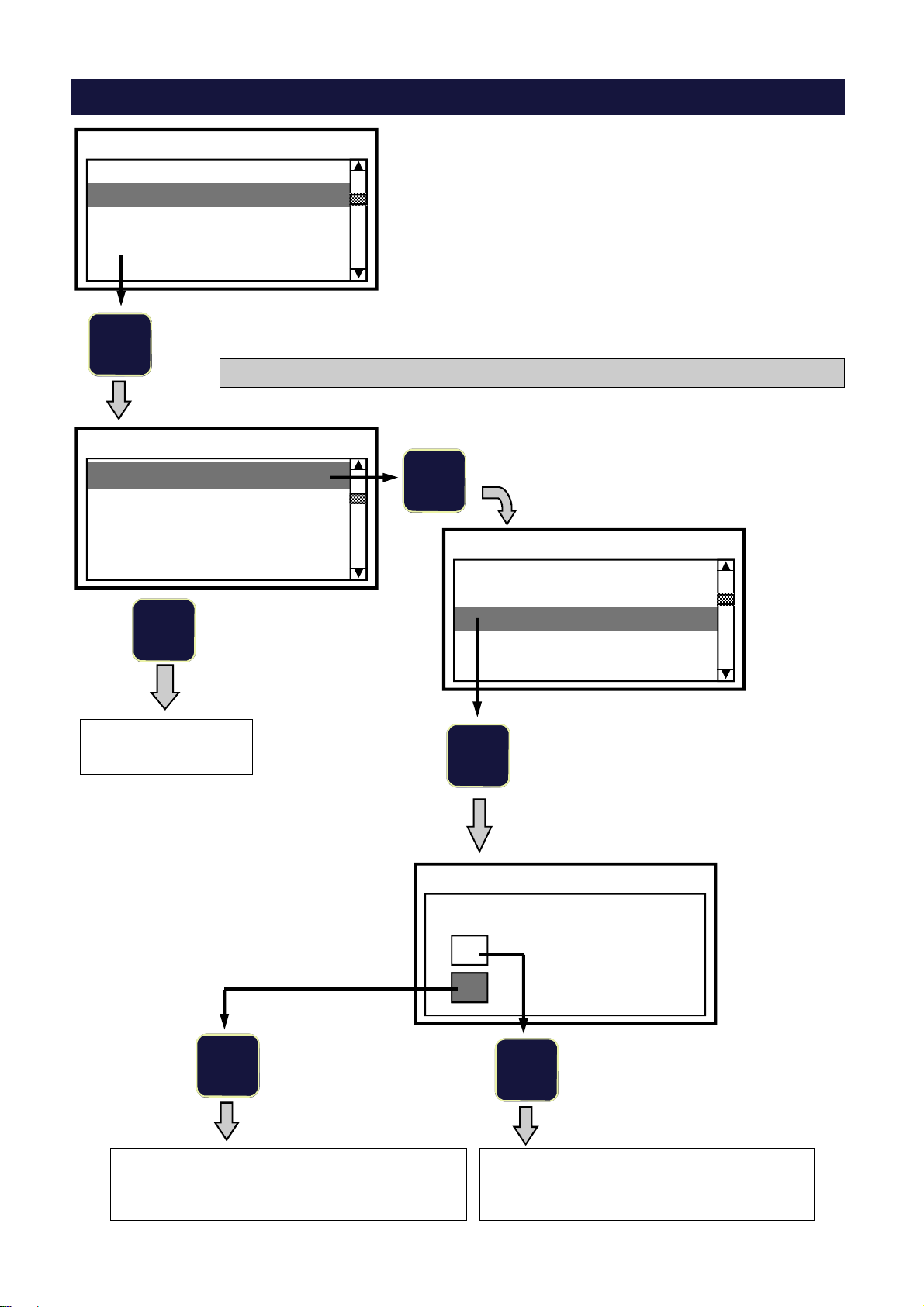
Opening a Configuration File
CONFIGURATION FILES
Save
Open
Delete
Send and Receive Files
6
Open
Existing File List
Enter File Name
8
The Open function is used to recall a file from the
instrument’s memory and make it “operative”.
This procedure can be performed in two different ways:
1. Opening a file from the existing file list.
2. Opening a file by entering the name.
1. Opening a file from the existing file list
6
Existing File List
ABCDEFGH
CFG12
CFG13
TXKBGFRY
1234ABCD
Next
page
Enter
6
CFG13
Confirm ?
NO
YES
Exits the menu and opens the selected
file. Normal operating mode is
automatically resumed
The keys scroll UP and DOWN
the list of existing files.
The key opens the selected file.
The key quits the menu step by step
until normal operating mode is resumed.
Enter
Enter
Select
Confirm
Exits the menu without opening the
selected file.
Display returns to Open menu.
34
Page 35
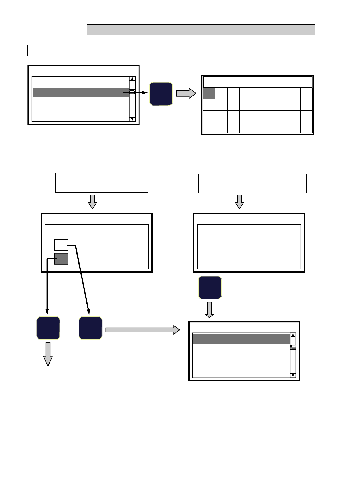
2. Opening a file by entering the name
From previous page
Open
Existing File List
Enter File Name
The procedures for entering the file name are
those described on page 28.
Refer to “Key Functions” chapter.
If the name just entered is correct
the display shows the following:
6
Opening a file
Entering the file name:
The following grid appears on the display.
The letter “A” is highlighted.
NAME:
A B D C E F H G I
J K M L N O Q P R
S T V U W X Z Y 0
1 2 4 3 5 6 8 7 9
If the name just entered is wrong
the display shows the following:
CFG13
Confirm ?
NO
YES
Enter
Enter Enter
Exits the menu and opens the file.
Normal operating mode is automatically
resumed
Select
Confirm
CFG14
Wrong or incomplete name
Back
4
Open
Existing File List
Enter File Name
35
Page 36
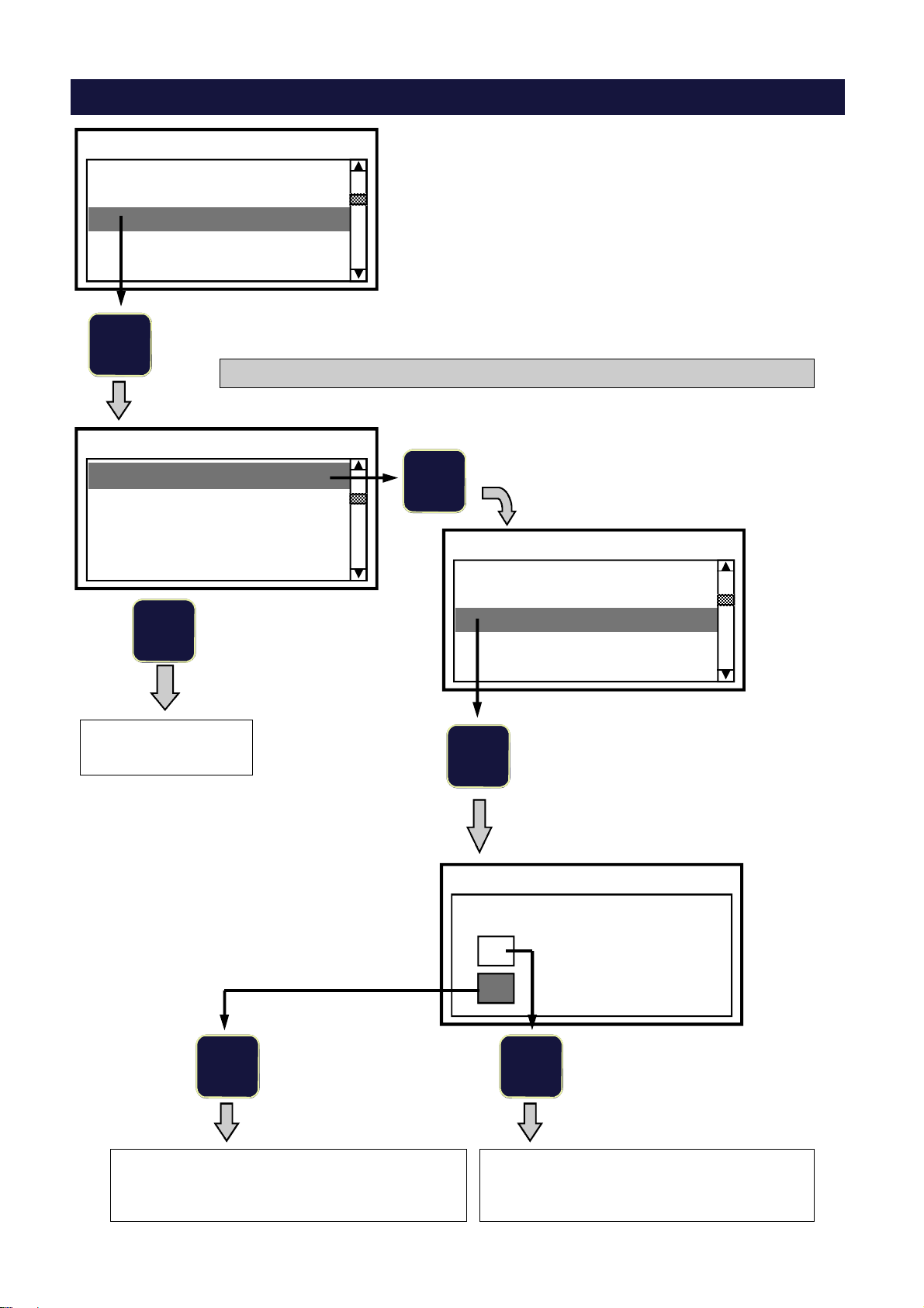
Deleting one of the files
CONFIGURATION FILES
Save
Open
Delete
Send and Receive Files
6
Delete
Existing File List
Enter File Name
Delete all Files
8
The Delete function is used to delete a file in the
instrument’s memory.
This procedure can be performed in two different ways:
1. Deleting a file from the existing file list.
2. Deleting a file by entering the name.
1. Deleting a file from the existing file list
6
ELENCO FILE ESISTENTI
Existing File List
ABCDEFGH
CFG12
CFG13
TXKBGFRY
1234ABCD
Next
Page
6
CFG13
Confirm ?
Exits the menu and deletes the
selected file. Normal operating mode is
automatically resumed
The keys scroll UP and DOWN
the list of existing files.
NO
YES
The key opens the selected file.
The key quits the menu step by
step until normal operating mode is
resumed.
Enter
Enter Enter
Select
Confirm
Exits the menu without deleting the
selected file.
Display returns to Delete menu.
36
Page 37
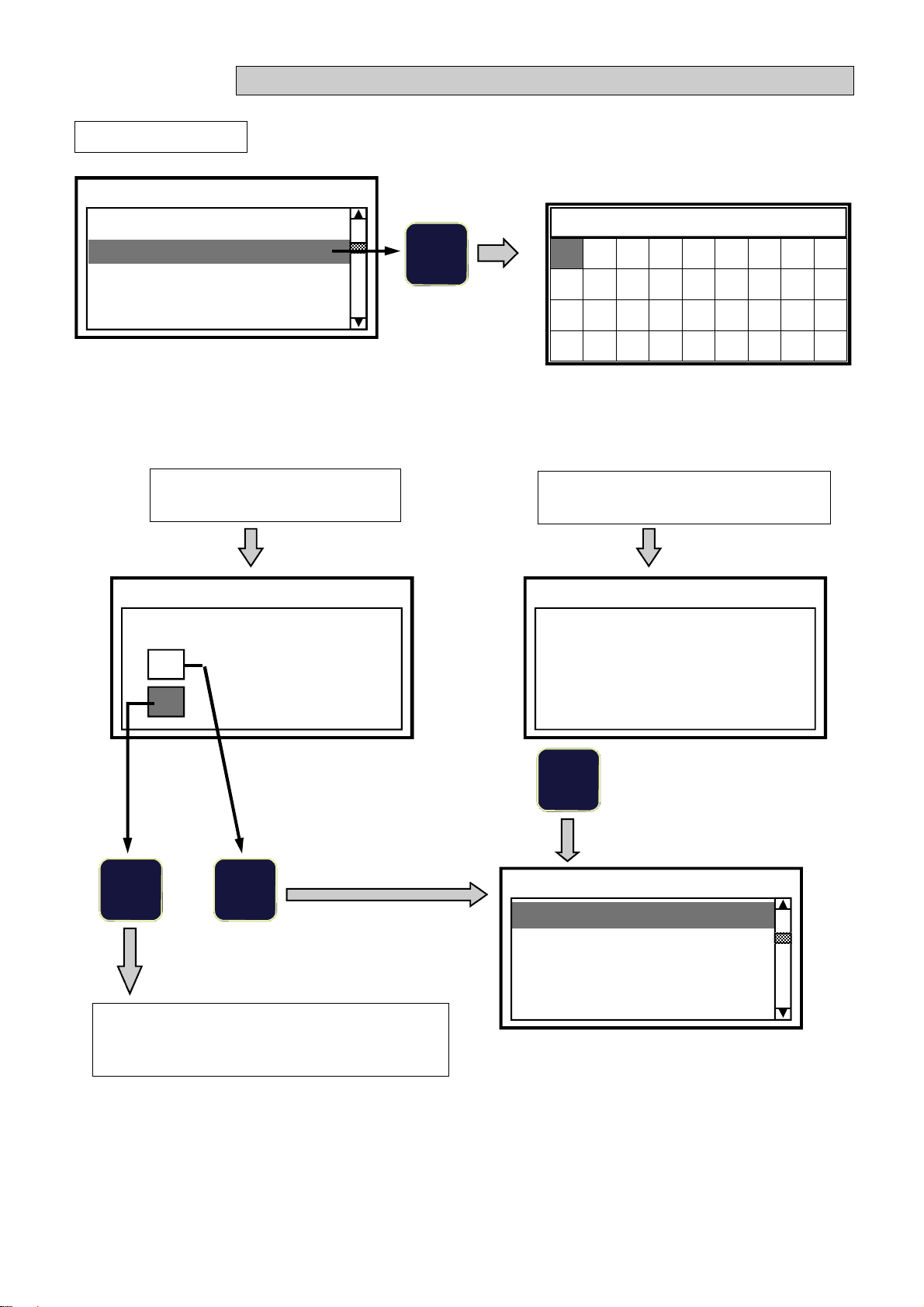
2. Deleting a file by entering the name
From previous page
Elimina
Delete
Existing File List
Enter File Name
Delete all Files
The procedures for entering the file name are
those previously described on page 28.
Refer to “Key Functions” chapter.
If the name just entered is correct
the display shows the following:
6
Deleting a file
Entering the file name:
The following grid appears on the display.
The letter “A” is highlighted.
NAME:
A B D C E F H G I
J K M L N O Q P R
S T V U W X Z Y 0
1 2 4 3 5 6 8 7 9
If the name just entered is wrong
the display shows the following:
CFG13
Confermi eliminazione File ?
Confirm ?
SI
NO
NO
YES
Enter
CFG13
Enter
Enter
Enter
Selezione
Select
Conferma
Confirm
Exits the menu and deletes the
selected file. Normal operating mode is
automatically resumed
CFG14
Wrong or incomplete name
Back
4
Delete
Existing File List
Enter File Name
Delete all Files
37
Page 38
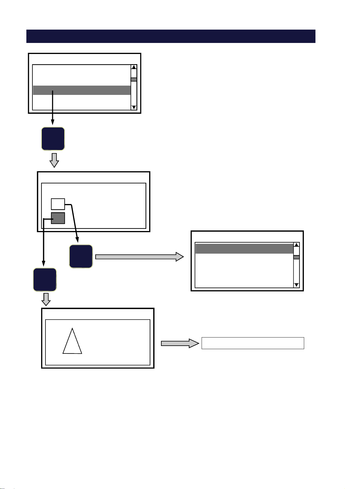
Elimina
Delete
Existing File List
Enter File Name
Delete all Files
6
CFG13
Delete all Files
Confermi eliminazione File ?
Confirm ?
SI
NO
NO
YES
Enter
Enter
Deleting all the files in the memory
Selezione
Select
Conferma
Confirm
Enter
Enter
Delete all Files
FILES
!
RESET
Delete
Existing File List
Enter File Name
Delete all Files
Back to normal operating mode
38
Page 39
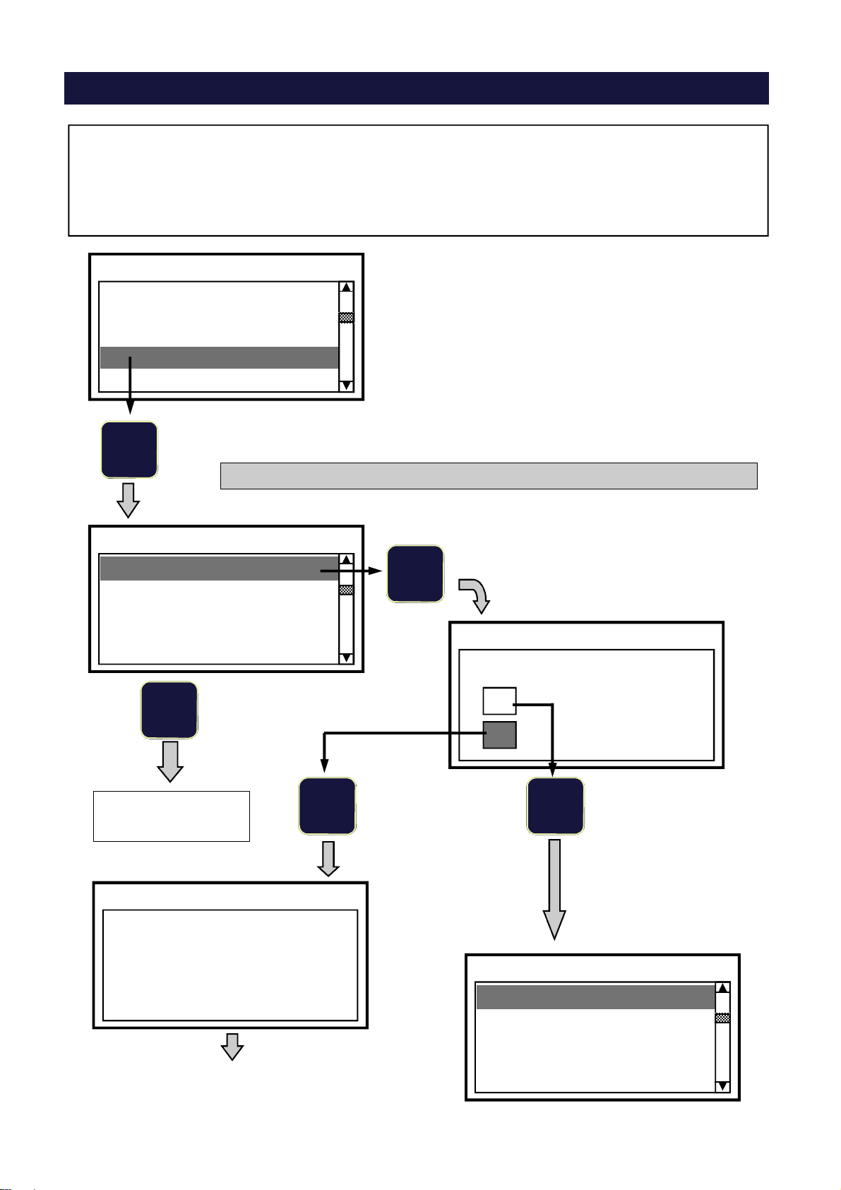
Transferring one file / all files
In order to transfer the configuration files to a PC or vice-versa, the following conditions must be satisfied:
1. Assure there is a valid RS-232 connection between the Load Cell Tester and the PC.
2. “Hyper Terminal” application active on the PC, in “Receive File” (from LC Tester to PC) or “Send
File” (from PC to LC Tester) mode.
3. Communication parameters: 9600, 8, N, 1.
CONFIGURATION FILES
Save
Open
Delete
Send and Receive Files
6
CONFIGURATION FILES
Send Current File
Send all Files
Receive File
8
The “Send and Receive Files” function is used to:
1. Send the current file to a computer only (the one
currently in use).
2. Send all the files in the LC Tester’s memory to a
computer (including the one currently in use).
3. Receive from a PC 1 Configuration File.
1. Sending the current file to a PC
6
Send Current File
Send the File CFG13
NO
YES
Enter
Select
Confirm
Next
page
CONFIGURATION FILES
File transfer in progress
Please wait...
File transfer completed
Enter Enter
CONFIGURATION FILES
Send Current File
Send all Files
Receive File
39
Page 40
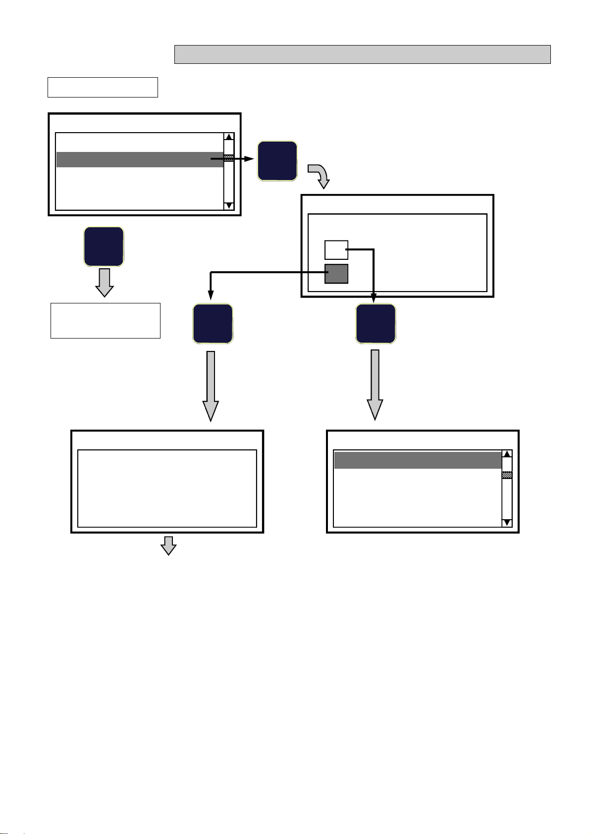
From previous page
CONFIGURATION FILES
Send Current File
Send all Files
Receive File
8
2. Sending all the files to a PC
6
Send all Files
Confirm ?
NO
YES
Enter
Select
Confirm
Next
page
CONFIGURATION FILES
Files transfer in progress
Please wait...
Files transfer completed
Enter Enter
CONFIGURATION FILES
Send Current File
Send all Files
Receive File
40
Page 41
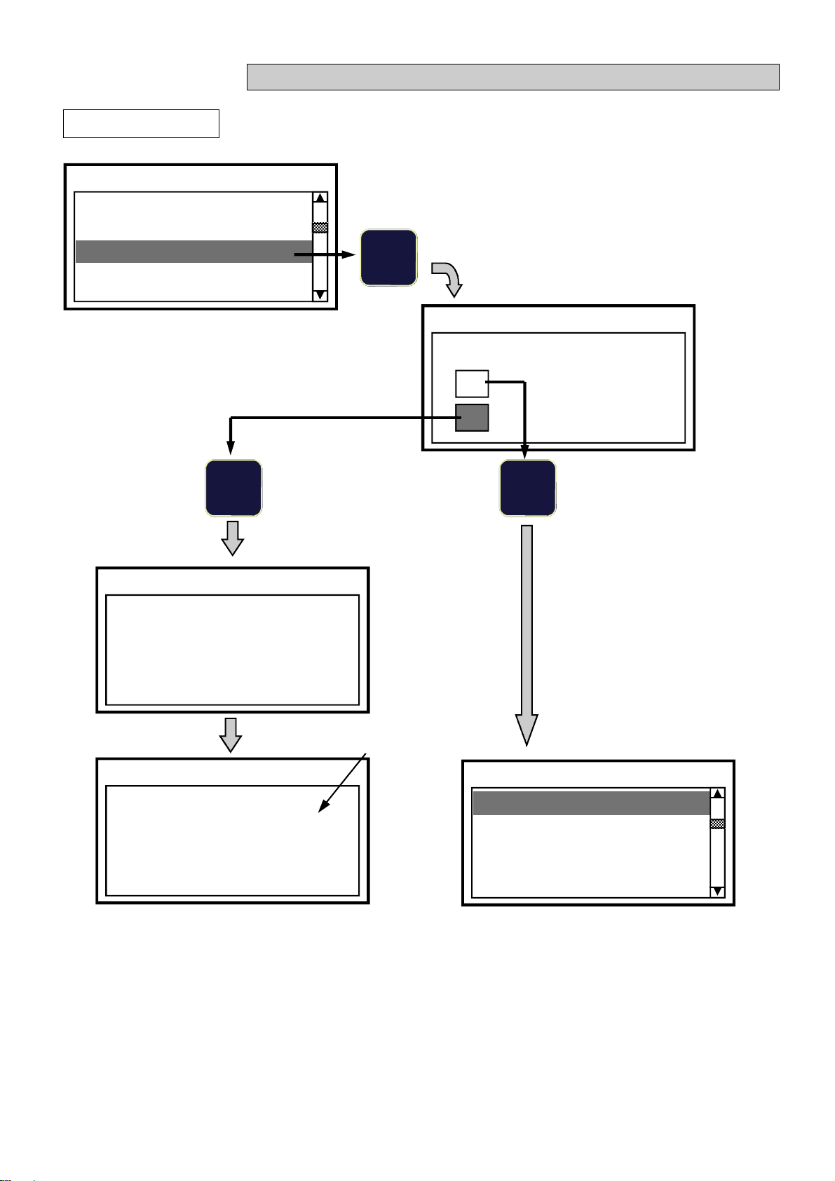
From previous page
CONFIGURATION FILES
Send Current File
Send all Files
Receive File
3. Receiving a Configuration File from a PC
6
Receive File
Activate ?
CONFIGURATION FILES
Receiving File
Please wait...
CONFIGURATION FILES
(2 sec.)
NO
YES
Enter
Select
Confirm
Enter Enter
CONFIGURATION FILES
File CFG13 received
NOTE:
Receiving a configuration file does not mean to make it operative.
The file just received is added to the list of existing files however, the LC Tester will continue normal operation.
41
Send Current File
Send all Files
Receive File
Page 42
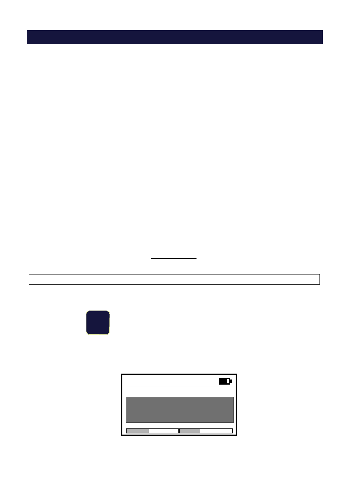
STORING THE mV/V LOAD CELL SIGNALS
This function is used to save the individual zero and span mV/V signals coming from the load cells into the
instruments memory.
Both the Zero and Span values can be saved (by “Zero” we mean the mV/V values coming from the
load cells when the weighing system is unloaded; by “Span” we mean the mV/V values corresponding
to a known weight applied on the weighing system).
The span value may not necessarily coincide with the weighing system’s full scale value.
The mV/V values can only be stored when the instrument is in “Load Cell Tester” mode, and the “mV/V
Input Signals” display view is selected (see Figure 1 on page 14).
The stored values are automatically associated to the Configuration File currently in use.
The stored mV/V values can be used as reference values for performing periodic checks on the load cells.
When operating the load cell tester in “Calibrator” mode, it can be used to generate a zero and span mV/V
output signal (based on the average of the individual signals) that were previously saved in memory.
These signals can be used to check or calibrate the Zero and Span of the weighing systems instrumentation.
The mV/V signals representing zero and span can only be saved into the load cell testers memory when:
The load cell tester is displaying the “mV/V Input Signals” (see Figure 1 on page 14).
One of the Configuration Files has been opened (see page 30)
Procedure:
Acquiring the Zero mV/V signals
Make sure that the weighing system is empty or unloaded prior to performing the following operation:
Press and hold the
8
key to save the zero mV/V signals
Once the Zero mV/V signals have been acquired, the following message appears momentarily on the display:
mV/V Input Signals
1 2
3 4
0.318 0.325
zero signals acquisition
done !
0.290 0.285
The stored values are automatically associated with the Configuration File currently in use.
42
Page 43
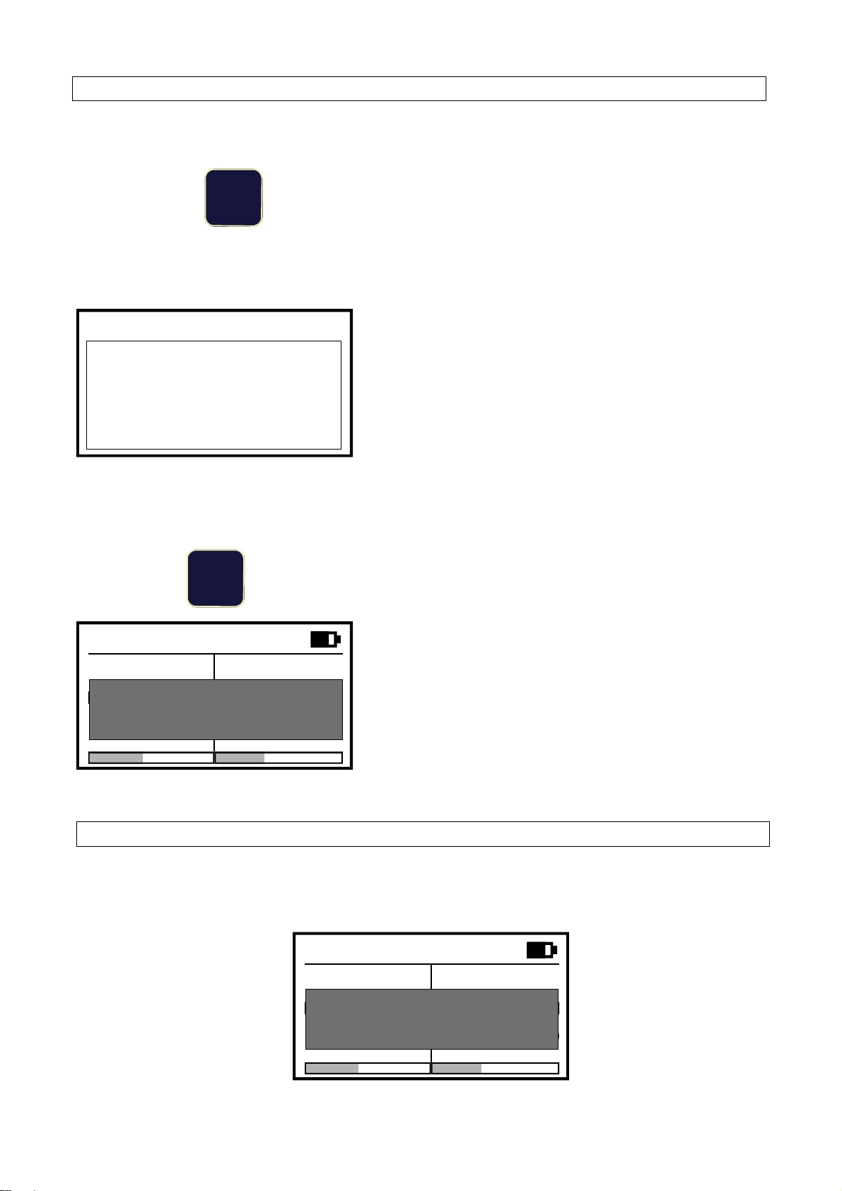
Acquiring the Span mV/V signals
Apply a known weight on the weighing system prior to performing the following operation
Press and hold the key to save the span mV/V signals
2
Once the Span mV/V signals have been acquired, the display prompts the following setting:
mV/V Input Signals
Enter weight value
XXXXXX u.m.
Note: “u.m.” = pre-selected Unit of Measurement
Enter the value of the known weight applied on the weighing system.
Refer to page 12 (Entering numerical data) for keys functions.
By pressing the
Enter
key, the following message appears for a while on the display:
mV/V Input Signals
1 2
3 4
1.214 1.221
FS signals acquisition
done !
1.185 1.180
After a while the message disappears automatically and
the LC Tester resumes normal operating mode
Warning message during the mV/V signals acquisition
If none of the Configuration Files have been opened previously, the following message will appear on the display
when trying to acquire the Zero or Span mV/V signals.
mV/V Input Signals
1 2
3 4
1.214 1.221
Open or select a file prior
to performing this function
1.185 1.180
43
Page 44
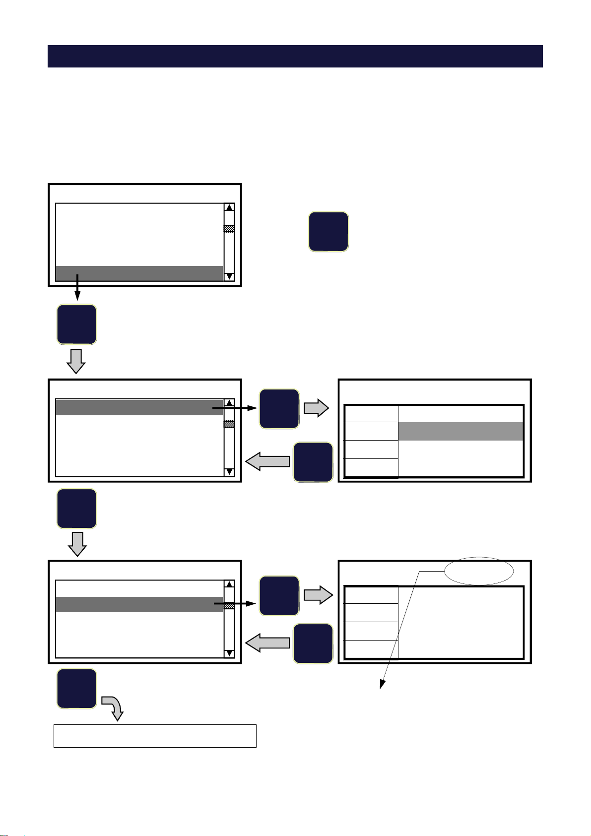
Reading the Zero and Span mV/V signals stored in memory
The user has the opportunity to read the zero and span mV/V values for each system simplifying any periodic
checks required on the load cells.
When recalling a Configuration File from memory, the Zero and Span mV/V values previously stored and assigned to the current file, are also recalled.
From “WEIGHING PARAMETERS” menu:
WEIGHING PARAMETERS
Load Cell Capacity
LC Sensitivity Values
Display Division Value
Configuration Files
Stored mV/V Signals
Press the to access this menu.
Enter
6
Stored mV/V Signals
Zero
Span
Exits the
procedure without saving any data if
no characters were
8
Stored mV/V Signals
Zero
Span
previously
entered.
6
6
4
4
Zero
L.C. 1
L.C. 2
L.C. 3
L.C. 4
Span 600 kg
L.C. 1
L.C. 2
L.C. 3
L.C. 4
0.318 mV/V
0.325 mV/V
0.290 mV/V
0.285 mV/V
1.214 mV/V
1.221 mV/V
1.185 mV/V
1.180 mV/V
4
Back to “WEIGHING PARAMETERS” menu.
Weight value associated to the Span mV/V signals.
(the one entered previously during the mV/V signals
acquisition). See top of page 39
44
Page 45
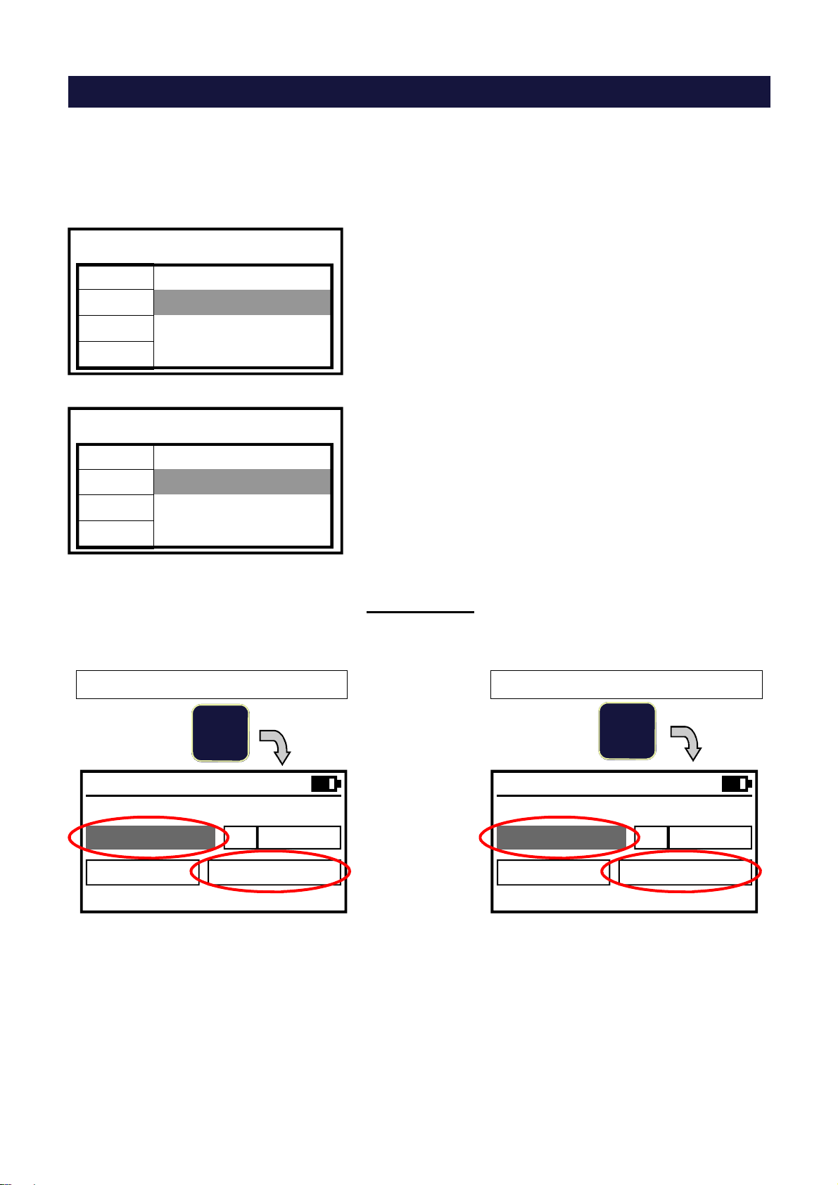
CALIBRATOR mode - GENERATING STORED mV/V LOAD CELL SIGNALS
The stored zero and span mV/V signals can be used to check or calibrate the Zero and Span points of the
instrumentation being used in weighing system.
The load cell tester will generate a mV/V signal for zero and span based on the average of the individual
signals previously stored in memory:
Zero
L.C. 1
L.C. 2
L.C. 3
L.C. 4
Span 600 kg
L.C. 1
L.C. 2
L.C. 3
L.C. 4
0.318 mV/V
0.325 mV/V
0.290 mV/V
0.285 mV/V
1.214 mV/V
1.221 mV/V
1.185 mV/V
1.180 mV/V
0.318 +
0.325 +
0.290 +
0.285 = 1.218 ÷ 4 = 0.304 mV/V
In this example 0.304 mV/V will be the value generated by the
LC Tester in order to reproduce the signal coming from the load
cells at zero point.
1.214 +
1.221 +
1.185 +
1.180 = 4.800 ÷ 4 = 1.200 mV/V
In this example 1.200 mV/V will be the value generated by the
LC Tester in order to reproduce the signal coming from the load
cells corresponding to a weight value of 600 kg.
Procedure:
Press the Test/Cal button to switch the LC Tester into CALIBRATOR mode
Generating the Zero signal Generating the Span signal
Press and hold
8
Press and hold
Stored mV/V signals
File: CFG13
+ 0.304 mV/V
V in +4.95 GW 0 kg
Press C key to exit Press C key to exit
The LC Tester generates 0.304 mV/V.
This signal is used to perform the zero
calibration of the weighing indicator.
NOTE: In this particular function the LC Tester is able to generate the Zero and Span mV/V values
only.
Press the C key in order to resume normal operation in CALIBRATOR mode.
+ 1.504 mV
Stored mV/V signals
File: CFG13
+ 1.200 mV/V
V in +4.95 GW 600 kg
The LC Tester generates 1.200 mV/V.
This signal is used to perform the span
calibration (600 kgs.) of the weighing
indicator.
2
+ 5.940 mV
45
Page 46
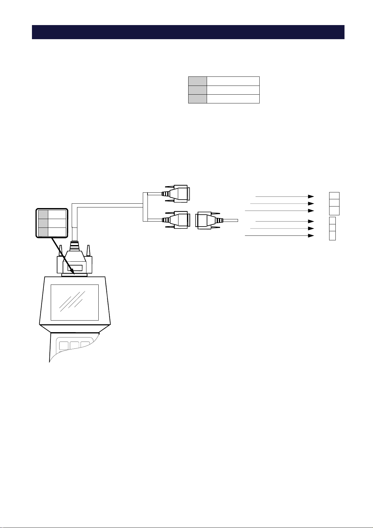
RS-232 CONNECTIONS
The bi-directional RS-232 communication allows transferring the Configuration Files from the load cell tester to
a computer and vice-versa.
The female 25 pin Sub-D connector installed on the LC Tester, includes terminals for the RS-232 connection:
LC Tester 25 pin Sub-D
connector pinout
2
5
18
The RS-232 connection to the PC can be established using Cable “B” .
PC Connettor
9 pin Sub-D
femmina
SGND
2
TXD
5
RXD
18
MC302
Connettor
9 pin Sub-D
maschio
DAT 400/500
Connettor
9 pin Sub-D
FEMMINA
GND
TXD
RXD
Connection
DAT 400
ROSSO
BIANCO
BLU
ROSSO
BIANCO
BLU
Connection
DAT 500
RXD
TXD
GND
RXD
TXD
GND
26
27
25
7
6
8
46
Page 47

PAVON E SI ST EMI S.R. L.
Via Tiberio Bianchi 11/13/15, 20863 Concorezzo (MB), ITALY
T 0039 039 9162656 F 0039 039 9162675 W en.pavonesistemi.it
Industrial Electronic Weighing Systems since 1963
 Loading...