

DAT 500
TECHNICAL MANUAL
For Analog/Probus/Devicenet versions
Digital Transmitter
Software version PW13081

Page II

Page 1
0316
TABLE OF CONTENTS
PRECAUTIONS .............................................................................................. Page 2
INTRODUCTION ........................................................................................... Page 3
TECHNICAL FEATURES ................................................................................... Page 4
INSTALLATION .............................................................................................. Page 5
FRONT PANEL OF THE INSTRUMENT .............................................................. Page 10
USING THE KEYBOARD ................................................................................. Page 11
INFO DISPLAY ............................................................................................... Page 13
VIEWING, ZEROING THE WEIGHT AND SELF-CALIBRATION ............................. Page 14
SETTING ....................................................................................................... Page 18
CHART OF THE MENU ................................................................................... Page 20
SETTING PARAMETERS ................................................................................... Page 22
CALIBRATION................................................................................................ Page 25
WEIGHTING PARAMETERS ............................................................................. Page 27
INPUT/OUTPUT PARAMETERS ......................................................................... Page 29
SERIAL OUTPUT PARAMETERS ......................................................................... Page 32
ANALOG OUTPUT PARAMETERS..................................................................... Page 36
SERIAL COMMUNICATION PROTOCOLS ........................................................ Page 38
FIELDBUS PROTOCOLS .................................................................................. Page 46
TROUBLESHOOTING ..................................................................................... Page 50
GROUNDING CONNECTIONS DAT500 ......................................................... Page 51
INTRINSIC SAFETY BARRIERS .......................................................................... Page 52
OPTION 24 VOLT POWER SUPPLY .................................................................. Page 53

Page 2
PRECAUTIONS
READ this manual BEFORE operating or servicing the instrument.
FOLLOW these instructions carefully.
SAVE this manual for future use.
CAUTION
The installation and maintenance of this instrument must be allowed
to qualified personnel only.
Be careful when you perform inspections, testing and adjustment
with the instrument on.
Perform the electrical connections in the absence of the power supply
Failure to observe these precautions may be dangerous.
DO NOT allow untrained personnel to work, clean, inspect, repair
or tamper with this instrument.
Page 3
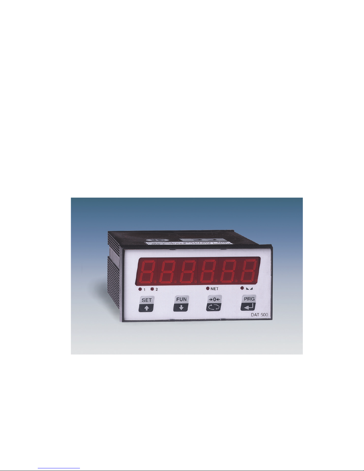
INTRODUCTION
The DAT 500 is a transmitter of weight to be combined with the load cells to detect the weight in every
situation.
The display allows easy reading of the weight, the status of the instrument, the setting parameters and
errors.
The 4 keys located below the display allow the operator to perform the functions of ZERO, TARE,
GROSS/NET switching, setting of the setpoints weight, setting and tare both theoretical than real.
The DAT 500 uses the serial port RS232 with ASCII and Modbus RTU protocols for connecting to a PC,
PLC and remote units. In parallel with the RS232, a USB port available.
They are always available 2 programmable weight setpoints and the control of the maximum weight
value reached (peak).
The RS422/RS485 serial output allows you to connect up to 32 addressable devices.
The availability of the most common fieldbuses, as an alternative to the RS422/RS485 port, also allows
the transmitter to interface with any supervision device currently offered by the market.
Available versions:
• DAT 500: weight transmitter with serial output RS232, RS422/RS485 and Peak function. Supported protocols are Modbus RTU, continuous, slave and the ones upon request. Two programmable
setpoints, 2 inputs and Peak function.
• DAT 500/A: version with the analog output.
• DAT 500/PROFIBUS: weight transmitter with serial output RS232 and PROFIBUS DP.
• DAT 500/DEVICENET: weight transmitter with serial output RS232 and DEVICENET.
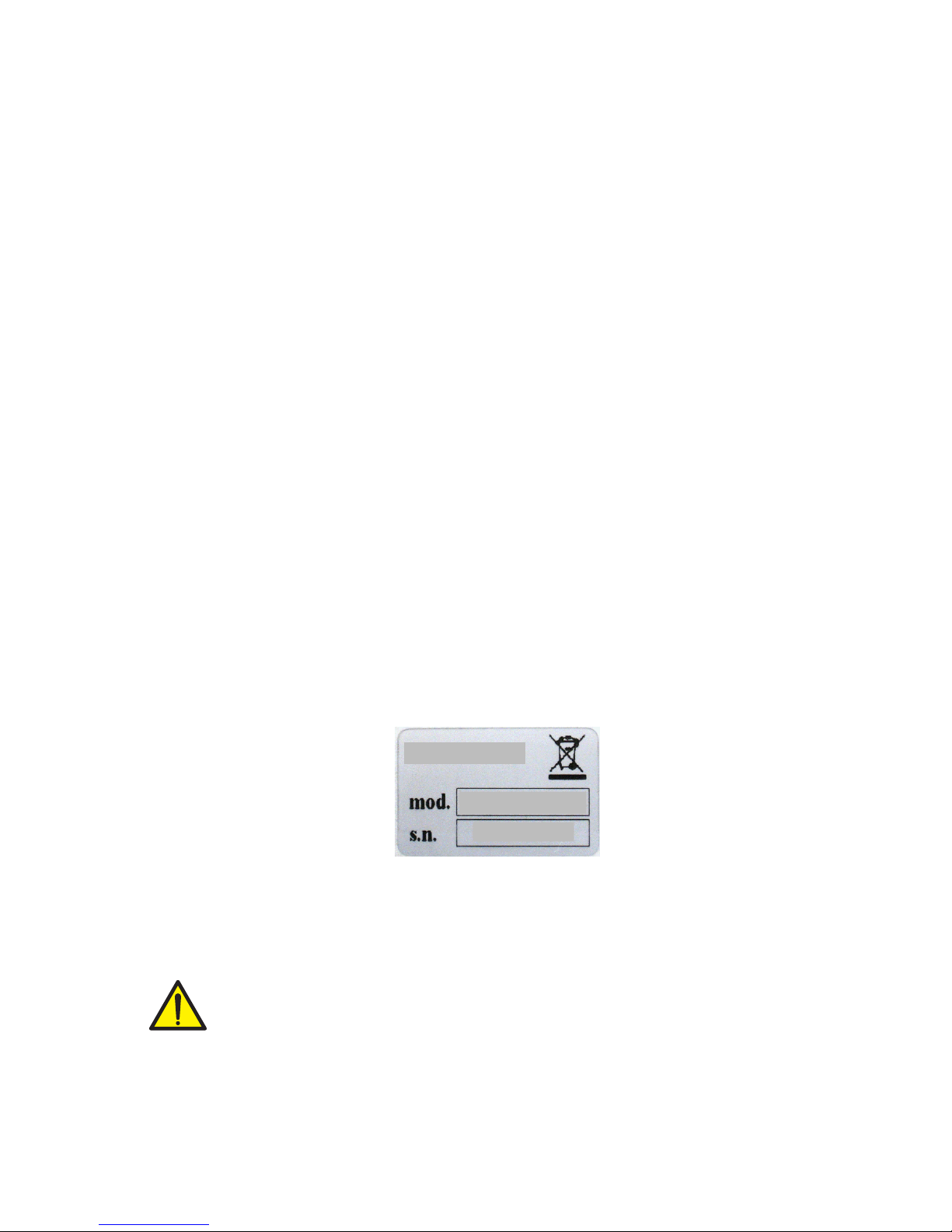
IDENTIFICATION PLATE OF THE INSTRUMENT
It’s important to communicate this data in the event of a request for information or information concerning the instrument together with the program number and version that are shown on the cover of the
manual and are displayed when the instrument is switched on.
WARNINGS
The following procedures must be performed by qualified personnel.
All connections must be performed when the instrument is turned off.

Page 4
TECHNICAL FEATURES
Power supply 24 Vdc ± 15 %
Max. absorption 5W
Insulation Class II
Installation category Cat. II
Operating temperature -10°C ÷ +40°C (max. humidity 85% non-condensing)
Storage temperature -20°C ÷ +50°C
Weight display Numerical with 6 red led digits and 7 segments (h 14
mm)
Led 4 LEDs of 3 mm
Keyboard 4 mechanical keys
Overall dimensions 106 mm x 58 mm x 90 mm (l x h x w)
Installation Panel mount
Case material self-extinguishing Noryl (UL 94 V1)
Connections Screw terminal boards, pitch 5.08 mm
Load cells power supply 5 Vdc/120mA (max 8 cells of 350W in parallel), short-
circuit protected
Input sensitivity 0.02 mV min.
Linearity 0.01% of the full scale
Temperature drift 0.001% of the full scale / °C
Internal resolution 24 bits
Resolution of the weight displayed Up to 60,000 divisions on the net capacity
Measurement range –0.5 mV/V to +3.5 mV/V
Frequency of weight capture 5 Hz - 50 Hz
Digital filter To be selected from 0.2 Hz to 25 Hz
Number of weight decimals 0 ÷ 3 decimal places
Zero calibration and full scale Automatic (theoretical) or executable from the keyboard.
Logic outputs 2 opto-isolated (dry contact), max 24Vdc / 60 mA each
Logic inputs 2 opto-isolated at 24 Vdc PNP (external power supply)
Serial port (# 2) RS232C or RS422/RS485)
Maximum cable length 15m (RS232) and 1000m (RS422 and RS485)
Serial protocols ASCII, Modbus RTU
Baud rate 2400, 9600, 19200, 38400, 115200 to be selected
Program code memory 64 Kbytes FLASH on-board reprogrammable from RS232
Data memory 2 Kbytes
Analog output (optional) Voltage or current
Resolution 16 bits
Calibration Digital from the keyboard
Impedance Voltage: min. 10KΩ; Current: max 300Ω
Linearity 0.03 % of the full scale
Temperature drift 0.001% of the full scale /°C
Fieldbus (optional PROFIBUS DP, DEVICENET,
Buffer dimension 128 byte IN - 128 byte OUT
Page 5
PRG
0
SET
FUN
1 2
NET
8.8.8.8.8.8.
PRECISE DAT 500
48
96
139
130
148
44
90
1
2
3
4
5
6
7
8
+24 Vdc
0 Vdc
INSTALLATION
GENERAL DATA
The DAT 500 is composed of a motherboard, on which you can add the options available; the motherboard is housed in a plastic enclosure.
The DAT 500 should not be immersed in water, subjected to jets of water and cleaned or
washed with solvents.
Do not expose to heat or direct sunlight.
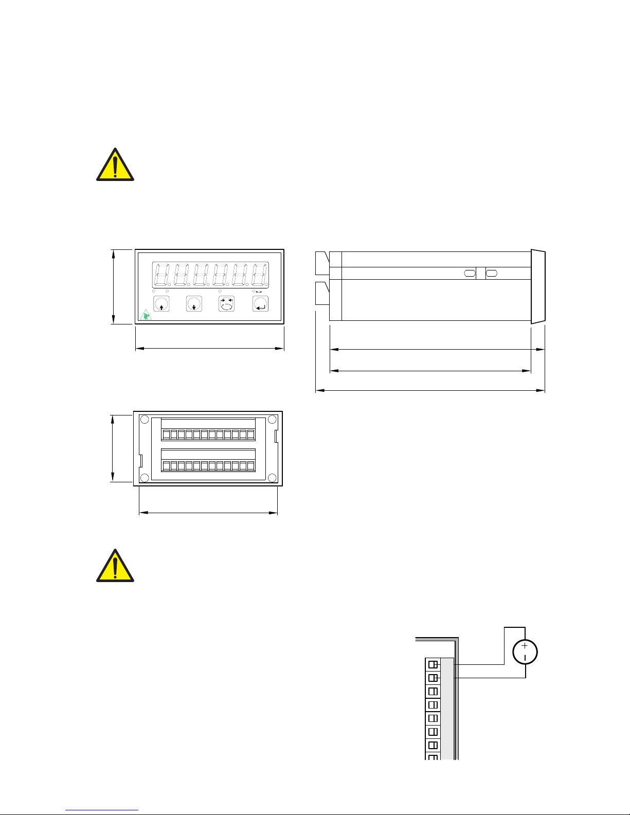
OVERALL DIMENSIONS
ELECTRIC INSTALLATION
The transmitter DAT 500 uses screw terminal boards, pitch 5.08 mm, for the electrical connection. The load cell cable must be shielded and channeled away from tension cables to
prevent electromagnetic interference.
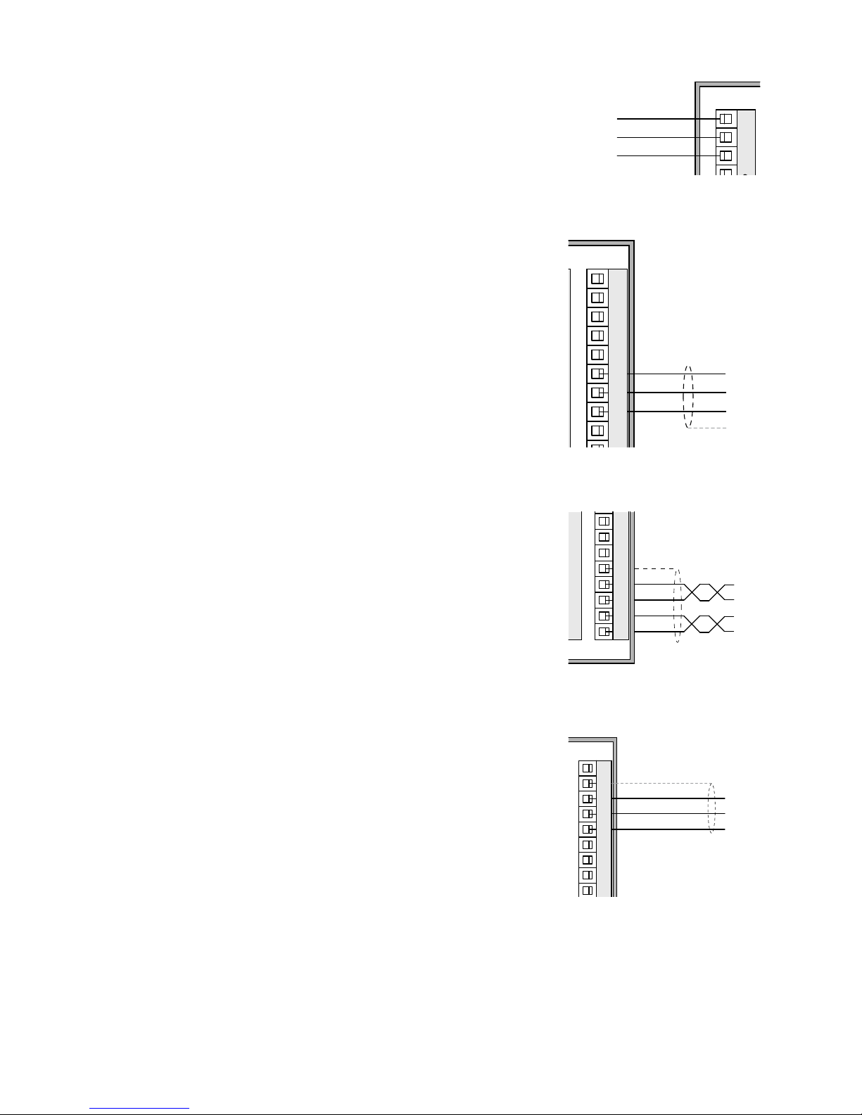
INSTRUMENT POWER SUPPLY
The instrument is powered through the terminals 1 and 2. The power
cord must be channeled separately from other cables.
The supply voltage is electrically isolated.
Power supply voltage: 24 Vdc/ ± 15% max. 5W.
Page 6
1
2
3
13
14
15
16
17
18
19
20
21
22
23
24
4
5
6
7
8
9
10
11
12
LOAD CELLS
- Exc
+ Exc
+ Sense
- Sense
- Sig
+ Sig
2+SGN
3-EXC
6+EXC
1-SGN
5+SNS
4-SNS
7SHD
+EXC
-EXC
+SGN
-SGN
SHD
1
2
3
4
5
+EXC
-EXC
+SGN
-SGN
SHD
1
2
3
4
5
+EXC
-EXC
+SGN
-SGN
SHD
1
2
3
4
5
+EXC
-EXC
+SGN
-SGN
SHD
1
2
3
4
5
J-BOX CGS4
DAT 500
SENSE-
SENSE+
I OUT+
V OUT+
SIGN-
SIGN+
C OUT
S GND
C OUT
OUT2
C IN
EXC-
EXC+
OUT1
IN2
RX-
RX+
TX -
TX+
IN1
TXD
RXD
24
12
11
10
23
24
19
22
21
20
14
15
16
17
18
13
9
8
3
4
5
12+
-
6
7
+24V
+EXC
-EXC
+SGN
-SGN
SHD
+EXC
-EXC
+SGN
-SGN
SHD
+EXC
-EXC
+SGN
-SGN
SHD
+EXC
-EXC
+SGN
-SGN
SHD
25 pin Connector
FIELDBUS
OPTIONAL
1
2
3
13
14
15
16
17
18
19
20
21
22
23
24
4
5
6
7
8
9
10
11
12
INPUTS
24 VDC
INPUT 1
INPUT 2
+
-
COM. INPUT
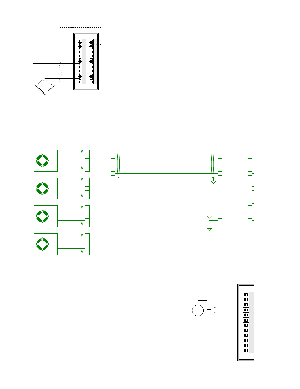
CONNECTIONS OF THE LOAD CELL/S
The cell/s cable must not be channeled with other cables, but must
follow its own path.
The instrument can be connected up to a maximum of 8 load cells
of 350 ohm in parallel. The supply voltage of the cells is 5 Vdc and
is protected by temporary short circuit.
The measuring range of the instrument involves the use of load cells
with a sensitivity of up to 3.5 mV / V.
The cable of the load cells must be connected to terminals 19-24.
In the case of 4-wire load cell cable, jumper the terminals 19 to 22
and 20 to 21.
Connect the cell cable shield to the terminal 2.
In the case of the usage of two or more load cells, use special junction boxes. Below please find their connection.
LOGIC INPUTS
The two logic inputs are opto-isolated.
The cable connecting the logic input should not be channeled with
the power cables.
The function of the two inputs is as follows:
INPUT1 Resetting the displayed value (gross, net or peak)
INPUT 2 PRINT
The activation of the two functions is accomplished by bringing the
external power supply 24 Vdc to the corresponding terminals as
shown in the figure.
Page 7
1
2
3
13
14
15
16
4
OUTPUTS
24 Vdc
100 mA Max
OUTPUT 2
OUTPUT 1
COM. OUTPUT
1
2
3
4
5
6
7
8
9
10
TXD
RXD
S.GND
SHIELD
RS232
(20m max)
1
2
3
13
14
15
16
17
18
19
20
21
22
23
24
4
5
6
7
8
9
10
11
12
S.GND
TXD+
TXD-
RXD+
RXD-
RS422/485
N°32 units max
(1000m max)
1
2
3
4
5
6
7
8
9
VOLTAGE (10 kΩ min)
ANALOG COM.
CURRENT (300 Ω max)
SHIELD
LOGIC OUTPUTS
The two opto-isolated relay outputs are the normally open contact.
The capacity of each contact is 24 Vdc, 100 mA max.
The cable connecting the outputs should not be channeled with the
power cables. The connection should be as short as possible.
SERIAL COMMUNICATION
RS232:
The RS232 serial port is always present and handles various protocols.
To achieve the serial connection, use a shielded cable, making sure
to connect the shield to one of the two ends: to terminal 8 if connected on the side of the instrument, to the ground if it is connected
on the other side.
The cable must not be channeled with power cables; the maximum
length is 15 meters (EIA RS-232-C), beyond which you should take
the optional RS485 interface.
RS422/RS485:
The serial port RS485 (2-wire) is present in the model DAT 500/
RS485.
To achieve the serial connection, use a suitable shielded cable, making sure to connect the shield to one of the two ends: to terminal
8 if connected on the side of the instrument, to the ground if it is
connected on the opposite side.
The cable should not be channeled with the power cables.
ANALOG OUTPUT (OPTIONAL)
The transmitter provides an analog output in current and voltage.
Analog voltage output: range from -10 to 10 V or -5 to 5 V, with
minimum load of 10 KΩ.
Analog current output: range from 0 to 20 mA or 4 to 20 mA. The
maximum load is 300 Ω.
To achieve the serial connection, use a suitable shielded cable, making sure to connect the shield to one of the two ends: to terminal
2 if connected on the side of the instrument, to the ground if it is
connected on the opposite side.
Attention: do not connect the analog output to devices that are
switched on.

Page 8
3
8
15
9 6
B_LINE
A_LINE
15
9 6
PROFIBUS DP CONNECTION
Pin Signal Description
1 - 2 - 3 B line +RxD/+TxD, level RS485
4 RTS Request to send
5 GND Ground (isolated)
6 + 5V Bus Output +5V termination (isolated)
7 - 8 A line -RxD/-TxD, level RS485
9 - Housing Cable shield Internally connected to protective
earth according to Profibus
specification
For connection to the Profibus Master, use a standard Profibus cable.
The typical impedance of the cable should be between 100 and
130 Ohms (f> 100 kHz). The cable capacity (measured between
conductor and conductor) should be less than 60 pF / m and the
minimum cable cross section should not be less than 0.22 mm2
In a Profibus-DP network, you can use either cable type A to type B
cable, depending on the required performance. The following table
summarizes the features of the cable to be used:
SPECIFICATION TYPE A CABLE TYPE B CABLE
Impedance from 135 to 165 ohm (f
= 3 – 20 MHz)
from 100 to 300 ohm (f
> 100 kHz)
Capacity < 30 pF/m < 60 pF/m
Resistance < 110 ohm/km Conductor cross
section
> 0,34 mm
2
> 0,22 mm
2
The following table shows the maximum length of the wires line with
cable type A and type B, function of the different communication
speed required:
Baud rate
(kbit/s)
9.6 19.2 187.5 500 1500 3000 6000 12000
Cable A
lenght (m)
1200 1200 1000 400 200 100 100 100
Cable B
lenght (m)
1200 1200 600 200 - - - -
For a reliable operation of the Fieldbus, should be used a line termination at both ends.
In the case of multiple DAT 500 instruments, use the line termination
at only one instrument.
For configuring the instrument, the GSD file is available (hms_1810.
GSD) that must be installed in the master.

Page 9
51
5
4
3
2
1
V-
V+
CAN_L
CAN_H
SHIELD
54321
DEVICENET CONNECTION
Pin Signal Description
1 V- Negative power bus
2 CAN_L CAN low bus line
3 SHIELD Shield
4 CAN_H CAN high bus line
5 V+ Positive power bus
To connect to the DeviceNet master, use a standard DeviceNet cable
or shielded twisted-pair cable as shown on the diagram.
The cable must not be channeled with power cables. For reliable
operation of the Fieldbus, should be used as a line termination of
121 Ω value between the terminal CAN_L and CAN_H.
For the configuration of the card is available ESD file that must be
installed in the master.

Page 10
SET FUN 0 PRG
1 2 NET
8.8.8.8.8.8.
PRECISE
DAT 500
FRONT PANEL OF THE INSTRUMENT
The DAT 500 has a bright 6-digit display, 4 status LEDs and four keys.
In this operating mode the display shows the weight and the LEDs indicate the status of weight and the
setpoints.
The set-up parameters are easily accessed and modified through the use of the three front buttons used
to select, edit, confirm and save the new settings.
DISPLAY
On the 6-digit display, it’s usually shown the scale weight. According to the various programming
procedures, the display is used for programming of the parameters to be stored in the memory, or the
messages that indicate the type of operation being carried out and help therefore the Operator in the
management and programming of the instrument.
LED INDICATORS
Below the display there are 4 LED indicators:
1 State of the logic output 1 (ON = closed contact OFF = open contact).
2 State of the logic output 2 (ON = closed contact OFF = open contact).
NET The displayed value is the net weight.
0 IT indicates the condition of stable weight.
Page 11
USING THE KEYBOARD
The instrument is programmed and controlled through the keyboard which has 4 keys, with double
functions. The selection of one of the key functions is established automatically by the instrument according to the operation in progress. In general, the management of the programming menus is done by
using the SET and FUN keys to scroll through the items; the PRG key is used to enter its sub-menu or
programmable parameter, while the 0 button allows you exiting the menu or returning to the top level.
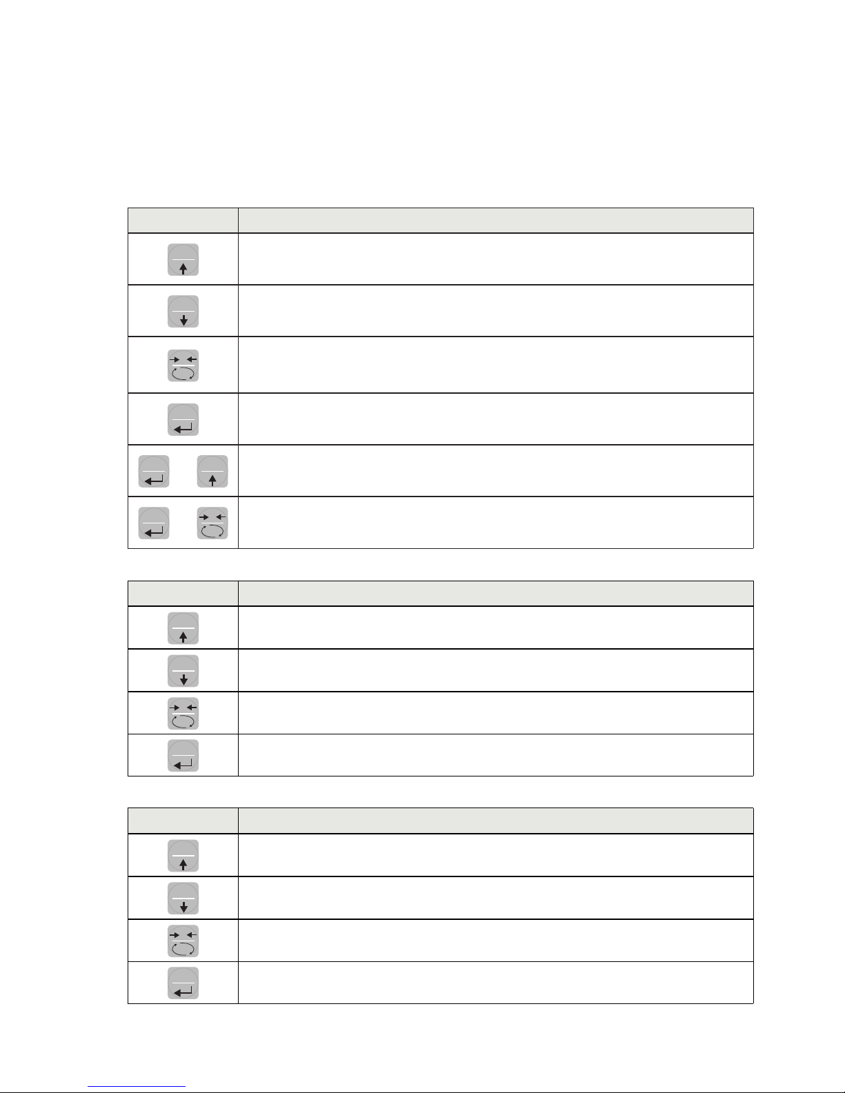
KEY FUNCTIONS DURING THE WEIGHT DISPLAY
SET
Access to the menu for the programming of the setpoints
FUN
Select the display view (gross weight, net weight).
(Long press) Selection of the weight/peak display
0
Resetting the displayed value (gross weight, net weight or peak).
(Press and hold for 5 sec.) Calibration of zero, to be executed only if its function
is enabled in the PARAM menu (see item “0 ALL”).
PRG
Sending the weight string on the serial line.
(Long press) Access to the quick set-up menu.
PRG
+
SET
(Press for 3 sec) Access to the setup menu.
PRG
+
0
(Press for3 sec) It accesses the keypad lock/unlock menu and auto-off function of
the display.
KEY
FUNCTION DURING THE MAIN MENU DISPLAY
SET
It selects the next parameter.
FUN
It selects the previous parameter.
0
It exits the programming menu or returns to the upper level.
PRG
It accesses the corresponding sub-menu or programming or confirms the selected
parameter.
KEY
FUNCTION WHEN SETTING THE NUMERICAL VALUES
SET
It increases the value of the flashing digit.
FUN
It decreases the value of the flashing digit.
0
It goes to the next digit.
PRG
It confirms the displayed value.

Page 12
KEY FUNCTION WHEN SETTING THE NUMERICAL VALUES
SET
It selects the next value.
FUN
It selects the previous value.
PRG
It confirms and store the displayed value.
EXIT FROM THE SETTING MENU
Press the
0
key to return to the main menu. Press the
0
. key again. It’s displayed “StORE?”.
Press the
PRG
key to return to the main menu.
To exit without saving any changes, switch off the instrument instead of pressing the
PRG
key.

Page 13
INFO DISPLAY
When the instrument is switched ON, you can test the display, then in sequence you can display the
identification code of the software and its version. Communication codes in the event of a request for
assistance.
ERRORS NOTIFICATION
In the operation mode, the display can report the following error codes.
ϩϩϩϩϩϩ the weight applied to the load cell exceeds by more than 9 divisions the maximum capacity
of the weighing system.
O-L Signal of the load cells absent or outside of the measurement range mV/V.
no CoN Fieldbus network disconnected
E-ProF PROFIBUS interface absent or not operating.
E-dNEt DEVICENET interface absent or not operating.
ϩϩϩϩϩϩ Dash that runs along the perimeter of the display: BLIND function enabled.
ErrNEN Memory error. Press the
PRG
key to reset the memory and return the parameters to their
default values. NOTE: it is also deleted the calibration performed.

Page 14
VIEWING, ZEROING THE WEIGHT AND SELF-CALIBRATION
After being calibrated, at the subsequent switches on, the display shows the current weight.
VIEWING THE NET WEIGHT/GROSS WEIGHT
Press the
FUN
key to toggle between the net weight and the gross weight and vice versa. The value
displayed is signaled by the LED NET (lit: net weight). If you have not entered the tare, the net weight
is equal to the gross weight.
In case of negative weight, it is displayed the minus sign before the most significant digit.
ZEROING, WEIGHT AND SELF-CALIBRATION
These two functions are performed by pressing
0
.
When the instrument is in the operation mode “Net” (“NET” LED on), the
0
key performs the self-
calibration.
When the instrument is in operation mode “Gross” (“NET” LED off), the
0
key clears the gross weight.
SELF-CALIBRATION
The execution of self-calibration is possible under the following conditions:
• Instrument under conditions of “Net” (NET” LED on).
• Positive gross weight.
• Gross weight not greater than the maximum capacity.
• Stable weight.
• Unstable weight. In this condition, we must distinguish two cases:
1. The weight stability control is enabled (the parameter “MOTION” (*) must be other than zero): the
command executed while the weight is unstable only has an effect if the weight stabilizes within 3
seconds from the moment the command was given.
2. The weight stability control is disabled (the parameter “MOTION” (*) is equal to zero): the executed
command takes effect immediately, even with unstable weight.
(*) The operating modes of the parameter “MOTION” are described at page 26
The self-calibration is retained in memory even after the power is turned off.
ZEROING
The reset command of the gross weight is used to correct for small zero shifts of the weighing system
during normal operation.
Normally these zero shifts are due to thermal drifts or to residues of material that accumulate on the
weighing system over the time.
To run the command, it is necessary that the instrument is under conditions of “Gross” (“NET” LED off)
and that the deviation of the weight with respect to the zero of the scale (the one performed with the
calibration of zero) does not exceed (in positive or negative) the number of divisions set in parameter
“0 BAND” (inside the PARAM menu; see page 28).
The reset command of the gross weight does not run if there is even one of the following conditions:

Page 15
• Unstable weight (with control of the stability of the weight enabled). In this case, the reset command
takes effect only if the weight stabilizes within 3 seconds or if the control of the weight stability is
disabled (parameter “MOTION “ equal to zero).
• Gross Weight greater (in positive or negative) than the number of divisions set in parameter “0
BAND” , when the setpoint of auto-calibration is not programmed.
The zero obtained with the resetting of the gross weight is retained in memory even after the power is
turned off.
The reset operation of the gross weight can be repeated several times, but the number of reset divisions
zero is added from time to time, so when the total exceeds the limit value set in parameter “0 BAND”,
the zero cannot be executed. In this case, it is necessary to calibrate the Zero.
Any auto-zero parameter setting when switching on (AUTO 0) reduces (or cancels, in the case of “AUTO
0”> “0 BAND”) the range of action of the reset command.
PEAK FUNCTION
The instrument continuously memorizes the peak value of the gross weight. The peak value is detected
at the same frequency of acquisition of the weight (see table on filters). In addition to visualization, the
peak value can be used in the following functions:
FUNCTION DESCRIPTION
LOGIC OUTPUT The setpoints can be set to have the peak value as a reference. (See the
procedure for setting the logic outputs operations).
SERIAL PORT Acquisition of the peak value (peak hold) through the CONTIN, AUTO, DE-
MAND, and MODBUS SLAVE protocols.
ANALOG OUTPUT
The analog output value can assume the value of the peak (peak old). (See
the procedure for setting the analog output).
Press the
FUN
key and hold it for 3 seconds until the left of the display shows the letter “P”.
INPUT / OUTPUT FUNCTIONS
INPUT
1
Resetting the displayed value (gross weight, net weight or peak). Closed for 5 sec. ->
Calibration of zero, to be executed only if its function is enabled in the PARAM menu (see
item “0 ALL”).
2
Sending the weight string on the serial line or print.
OUTPUT
1 Setpoint 1
2 Setpoint 2

Page 16
sEt 1
123456
SEt 2
123456
Increment
digit
Change
selected digit
EXIT
0SETSET
FUN
FUN
PRG
PRG
SET FUN
PRG
PRG
0
SET
Increment
digit
Change
selected digit
0
PROGRAMMING THE WEIGHT SETPOINTS
The set setpoint values are compared with the weight to drive its logic output. The comparison criterion
is established in the process of set-up of the logic I / O (see relevant paragraph).
To access the Setpoint setting, press the SET key and follow the instructions on the figure below.
During the step of setting the setpoints, both outputs are disabled. If the setpoint value in memory is 0,
the corresponding output is never enabled, regardless of the set-up of the selected setpoints. When the
weight is not detectable or out of range, all outputs are disabled (contact open or closed depending
on the MODE; see the relevant chapter).

Page 17
LOck
0000
blind
off
on
00
+
3 sec.
Select
digit
Change
selected digit
Select
digit
Change
selected digit
EXIT
KEYS CORRESPONDING
0
0
0
SET
SETSET
FUN
FUN
FUN
PRG
PRG
PRG
PRG
SET FUN
PRG
PRG
PRG
0SET FUN
PRG
0
KEYBOARD LOCK/UNLOCK FUNCTION
KEYBOARD LOCK/UNLOCK A function that allows you to enable or disable the keys individually.
When the keys are locked, the only way to access these settings is to press and hold pressed the PRG
+ 0 keys for 3 seconds. For more information on the function, refer to the block diagram above.
SWITCHING THE DISPLAY OFF This function allows turning off the display after a programmable time.
You can select ON / OFF of the parameter BLIND and the setting of a time; the time count starts from
the moment when, after exiting the setup menu, the display shows the weight value. After the set time,
the display turns off and only a dash appears. This dash cycles through the perimeter of the display
counterclockwise. When the display is off, also the 4 keys are disabled, regardless of how you set the
keypad lock (LOCK). The only way to access the settings will be PRG + 0.

Page 18
SETTING
GENERAL DATA
All functions of the DAT 500 are activated and modified by accessing a simple setup menu, shown
afterwards. All settings selected or activated remain stored even after switching off the transmitter.
The DAT 500 is preconfigured with a default setting. The following pages show the values of “Default”
for each parameter.
With the first on-site installation, it’s necessary to change some parameters in order to obtain a correct
indication of the displayed weight (Theoretical adjustment).
The settings of the setup menu can be changed using the front keys or via the utility “INOVATION 2”
software supplied.
CHANGING AND ENTERING THE PARAMETERS:
The setup parameters are grouped into a number of main menus.
To access the setup menu press the PRG key and then the SET key and hold down simultaneously for
3 seconds.
The display shows the message Conf1G that is the first of the main menus
Use the arrow keys to select the menu you want to change.
Press the PRG key to access the selected menu.
KEY FUNCTION DURING THE MAIN MENU PROGRAMMING
SET
It selects the next menu.
FUN
It selects the previous menu.
0
It exits the programming menu or returns to the upper level.
PRG
It accesses the corresponding sub-menu or programming or confirms the selected
parameter.
KEY FUNCTION WHEN SETTING THE NUMERICAL VALUES
SET
It increases the value of the flashing digit.
FUN
It decreases the value of the flashing digit.
0
It goes to the next digit.
PRG
It confirms and store the displayed value.

Page 19
KEY FUNCTION WHEN SETTING THE PROSED VALUES
SET
It selects the next value.
FUN
It selects the previous value.
PRG
It confirms and store the displayed value.
The menu parameters can assume values that can be set or selected.
NOTE To exit and save the modified data, press multiple times the
0
key until the display shown
StorE, then press
PRG
key to go back to the operating mode.

Page 20
Conf1G
CapaC
SEns1t
nEt
dEad L
dspd1J
S1GnaL
CoUnts
opNodE
UpLoad
dnLoad
CaL1br ParaN
fILtEr
Notion
auto 0
0 trac
0 band
1n-oUt
NodE 1
Hyst-1
t1NEr1
dELay1
NodE 2
Hyst-2
t1NEr2
dELay2
tEst1n
tstoUt
SEr1aL
baUd r
Prot-1
prot-2
AddrEs
Pr-Add
dELay
rEN-Co
data F
AnaLoG
f-sCaL
NodE
AnzEro
tEst
ranGE
OffsEt
StorE?
CaL
0
CaL
123456
60000
t-Nap
r-NaP
dELNap
baud2r
dN-Add
SET FUN
0 ALL
F
+
3 sec.
EXIT MENU
ENTER MENU
DEVICENET
1P-Add
SubnEt
SET FUN
SET FUN
ETHERNET IP
PROFINET
0
PRG
PRG
SET
SET
FUN
SET
FUN
SET
FUN
SET
FUN
SET
FUN
FUN
0 0
0 0 0
0
0 0
0
0
PRG
0
PRG
PRG
PRG PRG PRG
SET SET FUN SET FUN
SET FUN
SET FUN
SET FUN
SET FUN
SET FUN
SET FUN
SET FUN
SET FUN
SET FUN
FUNSET
SET FUN
SET FUN
SET FUN
SET FUN
SET FUN
SET FUN
SET FUN
SET FUN
SET FUN
SET FUN
SET FUN
SET FUN
SET FUN
SET FUN
SET FUN
SET FUN
SET FUN
SET FUN
SET FUN
SET FUN
SET FUN
SET FUN
SET FUN
SET FUN
SET FUN
SET FUN
FUN
PRG
0
0
PRG
SET
SET
SET FUN
SET FUN
SET FUN
SET FUN
SET FUN
DIAGRAM OF THE MENU

Page 21
CapaC
SEns1t
nEt
dEad L
dspd1J
S1GnaL
CaL1br
AnaLoG
StorE?
CaL
0
CaL
123456
60000
5 sec.
EXIT MENU
ENTER MENU
0
PRG
FUN
PRG
SET
SET FUN
SET FUN
SET FUN
SET FUN
SET FUN
SET FUN
SET FUN
FUN
PRG
0
0
PRG
SET
SET
PRG
Enter Value
PRG
PRG
Enter Value
PRG
PRG
Enter Value
PRG
PRG
Enter Value
PRG
PRG
Select Value
PRG
PRG
See Value
0
PRG
Enter Value
PRG
PRG
QUICK SETUP MENU

Page 22
Conf1G
PRG
SET
FUN
CaL1br
CapaC
SEns1t
nEt
dEad L
dspd1J
S1GnaL
CoUnts
opNodE
UpLoad
dnLoad
SET FUN
0
0
0
0
0
0
0
0
0
0
SET FUN
SET FUN
SET FUN
SET FUN
SET FUN
SET FUN
SET FUN
SET FUN
SET FUN
SET
FUN
PRG
Enter Value
PRG
PRG
Enter Value
PRG
PRG
Enter Value
PRG
PRG
Enter Value
PRG
PRG
Select Value
PRG
PRG
Read Value
PRG
Read Value
PRG
Select Value
PRG
PRG
PRG
Transmit setup data
to serial port
0
0
Receive setup data
from serial port
CONFIGURATION PARAMETERS
Through the setting of the parameters listed below, the theoretical Full Scale DAT 500 calibration is performed. You must complete these steps with the zero calibration described on page 23. The procedure
ensures a good accuracy of the system (maximum error <1% FS) if there are no mechanical problems.
Program the known values of total capacity and sensitivity of the load cells and the approximate values
of net capacity and calibration. If the parameter SENSIT is not programmed, it is taken the 2.0000
mV/V value.
If the parameter CAPAC is programmed other than 0, according to the data CAPAC, SENSIT, NET and
DEAD L , the instrument automatically runs the following functions:
• Resetting the linearization points.
• Selection of the value of the division, however, to be modified, to the best of 10,000 divisions.
• Calibration of the theoretical approximate calibration of the weight (zero and full scale).
• Automatic programming of the overload setpoint (= NET).
These functions are performed each time you change one of the 4 parameters shown.
When you change the DSPDIV selection., it is automatically recalculated to full-scale calibration. The
selections are incompatible with the calibration parameters or calibration in memory are not accepted.
The selection programmed in Opmode is read from the instrument when it is switched on and it makes
that the instrument operates in that way.
CAPAC CAPACITY OF THE WEIGHING SYSTEM
It defines the value corresponding to the sum of the rated capacity
of the load cells. In the case of systems with only one load cell and
“N” fixed supports, enter the capacity value of the cell for the total
number of supports. This figure represents the full scale value of the
weighing system.
Following the change of the parameter value, the theoretical tare of
the weight is recalculated.
Values: from 1 to 500000
Unit: the same of that displayed
Default: 10000
sEnsit LOAD CELLS SENSITIVITY
Set the value corresponding to the average sensitivity of the load
cells, in mV / V. The instrument accepts values between 0.5 and 4
mV / V. If no value if programmed, it’s assumed it is 2mV/V.
Following the change of the sensitivity value, the theoretical tare of
the weight is recalculated.
Values: from 0.5000 to 4.0000 mV/V
Default: 2.0000

Page 23
Conf1G
PRG
SET
FUN
CaL1br
CapaC
SEns1t
nEt
dEad L
dspd1J
S1GnaL
CoUnts
opNodE
UpLoad
dnLoad
SET FUN
0
0
0
0
0
0
0
0
0
0
SET FUN
SET FUN
SET FUN
SET FUN
SET FUN
SET FUN
SET FUN
SET FUN
SET FUN
SET
FUN
PRG
Enter Value
PRG
PRG
Enter Value
PRG
PRG
Enter Value
PRG
PRG
Enter Value
PRG
PRG
Select Value
PRG
PRG
Read Value
PRG
Read Value
PRG
Select Value
PRG
PRG
PRG
Transmit setup data
to serial port
0
0
Receive setup data
from serial port
nEt CAPACITY OF THE WEIGHING SYSTEM
Programming the net capacity of the weighing system. Values lower
than 1/10 of CAPAC are not accepted.
Values: from 1 to 500000
Unit: the same of that displayed
Default: 10000
dEad L FIXED CALIBRATION OF THE WEIGHTING SYSTEM
Programming the fixed calibration value of the weighting system.
Values: from 1 to 500000
Unit: the same of that displayed
Default: 00000
dsPd1J DIVISION VALUE
The ratio between the capacity of the system and the division value
represents the resolution of the system (number of divisions).
Following the change of the capacity of the system, it is automatically
selected the division value to the best of 10000 divisions.
Following the change of the division value, if the maximum capacity does not change, the calibration of the weight is automatically
corrected.
Value to be selected:
0.0001 - 0.0002 - 0.0005
0,001 - 0,002 - 0,005
0.01 - 0.02 - 0.05
0.1 - 0.2 - 0.5
1 -2 - 5
10 - 20 - 50
Default: 1
S1GnaL TESTING THE LOAD CELLS SIGNAL
It’s displayed the signal acquired from the load cells expressed in
mV/V.
CoUnts A/D CONVERTER INTERIOR POINTS TEST
View of the interior points of the instrument (1,000,000 at the maximum input signal).
oPNodE SELECTION OF THE OPERATING MODE
Selection of the operating mode of the device (display) when it is
switched on:
Value to be selected:
GROSS, NET, PEAK
Default: GROSS

Page 24
Conf1G
PRG
SET
FUN
CaL1br
CapaC
SEns1t
nEt
dEad L
dspd1J
S1GnaL
CoUnts
opNodE
UpLoad
dnLoad
SET FUN
0
0
0
0
0
0
0
0
0
0
SET FUN
SET FUN
SET FUN
SET FUN
SET FUN
SET FUN
SET FUN
SET FUN
SET FUN
SET
FUN
PRG
Enter Value
PRG
PRG
Enter Value
PRG
PRG
Enter Value
PRG
PRG
Enter Value
PRG
PRG
Select Value
PRG
PRG
Read Value
PRG
Read Value
PRG
Select Value
PRG
PRG
PRG
Transmit setup data
to serial port
0
0
Receive setup data
from serial port
UpLoad RECEIVING DATA FUNCTION
Receiving function from a serial of a file containing the setup data
that will be automatically set in the instrument.
dnLoad SENDING DATA FUNCTION
Sending function from a serial of a file with the content of the setup
memory of the instrument.
EXAMPLE OF SETTING/CALIBRATION
You must weigh a tank, with empty weight of 750 kg and with a
capacity of 1000 liters, containing a product with a specific gravity of 1.33 of which you want to read the weight with a display
resolution of 0.2 Kg.
Before proceeding with the configuration, you should make sure
that the load cells are connected properly to the unit and the tank
is empty. Then you can set the parameters.
They are used:
Nr 3 load cells with capacity of 1000 kg
Sensitivity of respectively 2.0015, 2.0008 and 1.9998 mV/V
(average value = 2.0007 mV/V)
Set the following values in the configuration parameters:
CAPAC = 3000
SEnS1t = 2.0007
nEt = 1500
dEad L = 0
dSpd1J = 0.2
Make sure that the value read in the S1GNAL parameter corresponds
with the calibration weight of the system according to the following
proportion:
3000:2.0007=750:X
Where X is the value of the signal expressed in mV/V corresponding
to the theoretical value of the weight of the empty tank. The value
should be about 0.5 mV/V.
Now you can proceed to the calibration described in the following
paragraph, or you can exit the configuration menu by saving the
data entered.
The instrument should indicate the value corresponding to the weight
of the empty tank (for example 756.8).
You can re-access the configuration menu and enter the weight value
read in the dEad L parameter and enter the value 756.8.
Quit the configuration menu by saving the data.
For greater accuracy, prepare some sample weights or the preweighed material on a certified scale and calibrate as described in
the next paragraph.

Page 25
SET
FUN
CaL1br
SET
FUN
ParaN
CaL
CaL
123450
PRG
SET
SET FUN
PRG
PRG
0
0
120000
CAL
Enter Load
Value
PRG
PRG
With unload
scale
35
0
Load Weight
CALIBRATION
The calibration described herein should be performed with the use of sample masses and/or product
pre-weighed on a weighing scale.
Before proceeding with the calibration of the full scale, always perform the zero calibration.
During the calibration phase, the display shows the weight intermittently with the inscription CaL.
ATTENTION: If you turn off the instrument without exiting the set-up menu, the programming executed
is not stored.
NOTE In the event that after calibration, the system shows linearity errors, you should verify that the
weighted structure is completely free of mechanical constraints.
ZERO CALIBRATION
Perform the operation when the scale has no items (including the
fixed tare), and when the weight is stable. The zero of the system is
done by pressing the key 0.
The weight displayed resets and the display shows Cal alternated
by 0. You can repeat this operation more times.
CALIBRATION OF FULL SCALE
Prior calibration load the sample weight on the system and wait for
the stabilization; the display shows a weight value.
Press the SET key to adjust the weight. The display shows the theoretical weight value with the first digit to the left flashing. With the
arrow keys, enter the actual weight loaded on the system starting
from the first flashing digit. Switch to the next digit by pressing 0.
The confirmation of the last digit (far right) with the PRG key corrects
the weight. The display shows CAL, by altering the actual weight
value entered.
If the set value is higher than the resolution offered by the instrument,
the weight is not accepted and the display shows an error message
for a few seconds.
This procedure can be repeated.
Press the PRG key again to return to the CaLIb. menu.
EXIT FROM CALIBRATION MENU
The exit from the menu CaLIb is performed by pressing the
0
key until the appearance of the message store?.
To store the new calibration and exit the setup menu, press the PRG
key.
To cancel the calibration of zero and full scale:
FUN +0 it cancels the zero calibration.
FUN + SET it cancels the calibration of the full scale.

Page 26
SET
FUN
CaL1br
SET
FUN
Param
CaL
CaL
LIn P1
PRG
SET
SET FUN
PRG
PRG
0
0
12000
LIn P2
Enter Load
Value P1
PRG
With unload
scale
35
0
CaL
Load Weight P1
4 sec.
24000
LIn P9
Enter Load
Value P2
PRG
SET FUN
0
120000
Enter Load
Value P9
PRG
SET FUN
0
0
0
0
0
Load Weight P2
Load Weight P9
PRG
000000
000000
PRG
000000
PRG
LINEARIZATION PROCESS
When planning the sample weight, values greater than the full scale,
or lower than the previous point, or when the weight is not stable,
are not accepted. If the entered value is accepted, it is proposed
the next step, otherwise still the same.
The linearization points are automatically reset each time you change
a data of the theoretical calibration or it is performed a full-scale
calibration.

Page 27
SET
FUN
ParaN
SET
FUN
In-oUt
f1LtEr
Not1on
auto 0
0 trac
0 band
0
0
0
0
0
PRG
SET FUN
SET FUN
SET FUN
SET FUN
SET FUN
PRG
Select Value
PRG
PRG
Select Value
PRG
PRG
Enter Value
PRG
PRG
Select Value
PRG
PRG
Enter Value
PRG
0 ALL
0
SET FUN
PRG
Select Value
PRG
WEIGHTING PARAMETERS
The parameters in this menu allow you to adjust the timing of the acquisition and updating of the display
and the manual or automatic zeroing that the transmitter performs.
F1LtEr WEIGHT FILTER
This parameter adjusts the refresh speed of the display and the serial
and analog output.
Low values of the filter speed up the display refresh.
High values of the filter slow down the display refresh.
Value Update Response
0 50 Hz 25 Hz
1 50 Hz 16 Hz
2 25 Hz 8 Hz
3 25 Hz 5 Hz
4 25 Hz 2.5 Hz
5 10 Hz 1.5 Hz
6 10 Hz 1 Hz
7 10 Hz 0.7 Hz
8 5 Hz 0.4 Hz
9 5 Hz 0.2 Hz
Default: 5
Notion WEIGHT STABILITY
This parameter defines the divisions number needed to deem the
weight stable.
A large number of divisions allows the transmitter to detect quickly
the weight stability, which is needed when executing tare and print
commands.
Value Change
0 Always stable weight
1 Stability determined quickly
2 Stability determined with medium parameters
3 Stability determined accurately
4 Stability determined with the highest accuracy
Default: 2
Auto 0 AUTOZERO UPON SWITCHIN ON
This parameter defines the value of the maximum resettable weight
when the instrument is switched on.
This operation corresponds to a zero calibration of the system and
is executed only if the weight is stable and below the set value.
Value from 0 to the value of the CAPAC parameter.
Default: 0

Page 28
SET
FUN
ParaN
SET
FUN
In-oUt
f1LtEr
Not1on
auto 0
0 trac
0 band
0
0
0
0
0
PRG
SET FUN
SET FUN
SET FUN
SET FUN
SET FUN
PRG
Select Value
PRG
PRG
Select Value
PRG
PRG
Enter Value
PRG
PRG
Select Value
PRG
PRG
Enter Value
PRG
0 ALL
0
SET FUN
PRG
Select Value
PRG
0 trAc TRACKING THE ZERO
This function allows you to perform a momentary zero calibration
compensating for the temperature drift of the weight.
When you switch off the transmitter, it automatically returns to the
previous zero calibration.
The maximum weight resettable by this parameter is 2% of the range
of the system.
To disable this feature, use the value 0.
Value Change
0 Control OFF
1 0.5 div/sec
2 1 div/sec
3 2 div/sec
4 3 div/sec
Default: 0
0 band ZERO BAND
This parameter defines the number of divisions resettable by the
pressure of the front button of zero or by Input 1.
Values: from 0 to 200
Default: 100
0 ALL ZERO CAL
Enables the function that allows to perform zero calibration by pressing and holding the 0 key or input 1 for 5 sec.
Value:
Off Function disabled
On Function Enabled
Default: Off

Page 29
SET
FUN
In-oUt
SET
FUN
SEr1aL
NodE 1
0
PRG
SET FUN
PRG
Select Value
Hyst-1
t1NEr1
dELay1
NodE 2
0
0
0
0
SET FUN
SET FUN
SET FUN
SET FUN
PRG
Enter Value
PRG
PRG
Enter Value
PRG
PRG
Enter Value
PRG
PRG
Hyst-2
t1NEr2
dELay2
tEst1n
tstoUt
0
0
0
0
0
SET FUN
SET FUN
SET FUN
SET FUN
SET FUN
PRG
Enter Value
PRG
Enter Value
PRG
Enter Value
PRG
PRG
PRG
Read and
change status
Read and
change status
PRG
Select Value
PRG
Select Value
PRG
Select Value
PRG
Select Value
PRG
Select Value
PRG
Select Value
PRG
Select Value
PRG
0
0
PRG
PRG
INPUT/OUTPUT PARAMETERS
NodE 1 SETPOINT 1 OPERATION MODE
Select 4 operation criteria of the setpoint 1 in sequence:
NET The relay output is active in Net Weight mode
GROSS The relay output is active in Gross Weight mode
PEAK The relay output is active in Peak mode
Default: GROSS
Comparison with the net weight, gross weight or the peak. In this
last case, the comparison is made with the last peak value acquired,
even when the peak function is not active.
N.O. The relay 1 is normally open
N.C. The relay 1 is normally closed
Default N.O.
POS. The output is operating with positive weight
NEG. The output is operating with negative weight
Default: POS
NORML Output 1 is active with unstable weight
STABL The output is active with stable weight
Default: Norml
Hyst-1 HYSTERESIS OF THE SETPOINT 1
Hysteresis value than the setpoint value set.
Value: from 0 to 999
Default: 2
t1NEr1 SETPOINT 1 TEMPORIZATION
Value of time, in tenths of a second, during which, when the weight
value set is overcome, the output relative to setpoint 1 remains
enabled.
After this time, even if the weight value is still above the setpoint, the
output is automatically disabled.
The function is not activated if the programmed time is equal to zero.
Value: from 0 to 999
Default: 0
dELay1 SETPOINT 1 DELAY
Value of time, in tenths of a second, after which, when the weight value set is overcome, the output relative to setpoint 1 remains enabled.
The function is not activated if the programmed time is equal to zero.
Value: from 0 to 999
Default: 0

Page 30
SET
FUN
In-oUt
SET
FUN
SEr1aL
NodE 1
0
PRG
SET FUN
PRG
Select Value
Hyst-1
t1NEr1
dELay1
NodE 2
0
0
0
0
SET FUN
SET FUN
SET FUN
SET FUN
PRG
Enter Value
PRG
PRG
Enter Value
PRG
PRG
Enter Value
PRG
PRG
Hyst-2
t1NEr2
dELay2
tEst1n
tstoUt
0
0
0
0
0
SET FUN
SET FUN
SET FUN
SET FUN
SET FUN
PRG
Enter Value
PRG
Enter Value
PRG
Enter Value
PRG
PRG
PRG
Read and
change status
Read and
change status
PRG
Select Value
PRG
Select Value
PRG
Select Value
PRG
Select Value
PRG
Select Value
PRG
Select Value
PRG
Select Value
PRG
0
0
PRG
PRG
NodE 2 SETPOINT 2 OPERATION MODE
Select 4 operation criteria of the setpoint 2 in sequence:
NET The relay output is active in Net Weight mode
GROSS The relay output is active in Gross Weight mode
PEAK The relay output is active in Peak mode
Default: GROSS
Comparison with the net weight, gross weight or the peak. In this
last case, the comparison is made with the last peak value acquired,
even when the peak function is not active.
N.O. The relay 2 is normally open
N.C. The relay 2 is normally closed
Default N.O.
POS. The output is operating with positive weight
NEG. The output is operating with negative weight
Default: POS
NORML Output 2 is active with unstable weight
STABL Output 2 is active with stable weight
Default: Norml
Hyst-2 HYSTERESIS OF THE SETPOINT 2
Hysteresis value than the setpoint value set
Value: from 0 to 999
Default: 2
t1NEr2 SETPOINT 2 TEMPORIZATION
Value of time, in tenths of a second, during which, when the weight
value set is overcome, the output relative to setpoint 2 remains
enabled.
After this time, even if the weight value is still above the setpoint, the
output is automatically disabled.
The function is not activated if the programmed time is equal to zero.
Value: from 0 to 999
Default: 0
dELay2 SETPOINT 2 DELAY
Value of time, in tenths of a second, after which, when the weight value set is overcome, the output relative to setpoint 2 remains enabled.
The function is not activated if the programmed time is equal to zero.
Value: from 0 to 999
Default: 0

Page 31
SET
FUN
In-oUt
SET
FUN
SEr1aL
NodE 1
0
PRG
SET FUN
PRG
Select Value
Hyst-1
t1NEr1
dELay1
NodE 2
0
0
0
0
SET FUN
SET FUN
SET FUN
SET FUN
PRG
Enter Value
PRG
PRG
Enter Value
PRG
PRG
Enter Value
PRG
PRG
Hyst-2
t1NEr2
dELay2
tEst1n
tstoUt
0
0
0
0
0
SET FUN
SET FUN
SET FUN
SET FUN
SET FUN
PRG
Enter Value
PRG
Enter Value
PRG
Enter Value
PRG
PRG
PRG
Read and
change status
Read and
change status
PRG
Select Value
PRG
Select Value
PRG
Select Value
PRG
Select Value
PRG
Select Value
PRG
Select Value
PRG
Select Value
PRG
0
0
PRG
PRG
tEst1n LOGIC INPUTS TEST PROCEDURE
The display shows the inputs status.
0 = input disabled
1= input activated.
The input 1 corresponds to the 1a value on the left.
Enable and disable the inputs to check the corresponding state on
the display. During this procedure, the normal function of the inputs
is not active. Use this procedure only to check the hardware.
tstoUt LOGIC OUTPUTS TEST PROCEDURE.
The display shows the outputs status.
0 = output disabled, 1= output activated.
The input 1 corresponds to the 1a value on the left.
During this procedure, the LEDs reflect the state of the outputs. To set
the digits, use the keys as for the numeric settings.
During this procedure, the normal function of the outputs is not active.
Use this procedure only to check the hardware.

Page 32
SET
FUN
SEr1aL
SET
FUN
Config
baUdr
prot-1
prot-2
0
0
0
PRG
SET FUN
SET FUN
SET FUN
PRG
Select Value
PRG
PRG
Select Value
PRG
PRG
Select Value
PRG
AddrEs
0
SET FUN
PRG
Enter Value
PRG
SERIAL OUTPUT PARAMETERS
This menu allows you to set the serial ports COM1 and COM2 and the communication parameters.
The instrument has two independent serial ports:
COM1 with RS232 or RS422/RS485 interface
COM2 with optional FIELDBUS interface.
baUd r BAUD RATE COM1
It defines the baudrate of the RS232 serial port.
The value must be set to the same value of the PC / PLC or remote
display.
Value to be selected:
2400
9600
19200
38400
115200
Default: 9600
baud2r BAUD RATE COM2 (DEVICENET VERSION)
It defines the baudrate of the DEVICENET interface.
The value must be set to the same value of the PC/PLC.
Value to be selected:
125 250 500 DeviceNet
Default:
125 DeviceNet
Prot-1 COM1 PROTOCOL
It defines how to use the RS232 serial port
None: Serial communication OFF
Contin: Continuous transmission of the weight string. It can be used,
for example, to drive a weight repeater. See details in the relevant
paragraph.
Demand: When the Operator presses the front button or through
Input 2, a string of weight is transmitted. The command is accepted
if the weight is stable. Between two consecutive transmissions the
weight must have a variation of at least 20 divisions.
Autom-: It’s automatically transferred to a string of weight when the
weight stabilizes at a value higher than the minimum weight (20
divisions). Between two consecutive transmissions, the weight must
have a variation of at least 20 divisions.
Slave: ASCII protocol. See details in the relevant paragraph.

Page 33
SET
FUN
SEr1aL
SET
FUN
Config
baUdr
prot-1
prot-2
0
0
0
PRG
SET FUN
SET FUN
SET FUN
PRG
Select Value
PRG
PRG
Select Value
PRG
PRG
Select Value
PRG
AddrEs
0
SET FUN
PRG
Enter Value
PRG
Modbus: MODBUS RTU (slave) protocol. used only if PROT-2 is
configured equal NONE. See details in the relevant paragraph.
Selectable communication patrameters:
n-8-1
n-8-2
E-8-1
o-8-1
Default: n-8-1
Print: Data transfer to the printer.
Value to be selected:
None
Contin
Demand
AutomSlave
Modbus
Print
Default: None
Prot-2 COM2 PROTOCOL:
It defines the Fieldbus use mode
None: Serial communication OFF
PROFIB: PROFIBUS fieldbus (if there is an optional board)
DEVNET: DEVICENET fieldbus (if there is an optional board)
Value to be selected:
None
Profib
Devnet
Default:
None

Page 34
SET
FUN
SEr1aL
SET
FUN
Config
baUdr
prot-1
prot-2
IP-Add
subnEt
dELay
rEN-Co
t-NAP
r-Nap
dELNap
0
0
0
0
0
0
0
0
0
0
PRG
SET FUN
SET FUN
SET FUN
SET FUN
SET FUN
SET FUN
SET FUN
SET FUN
SET FUN
SET FUN
PRG
Select Value
PRG
PRG
Select Value
PRG
PRG
Select Value
PRG
PRG
PRG
PRG
Enter Value
PRG
Remote
connection
PRG
PRG
PRG
0
data F
0
SET FUN
PRG
Enter Value
PRG
PRG
trasNEnd-oh
0
rECEIV
End-oh
ErasE
End-oh
PRG
0
IP-Ad1
PRG
000
123
PRG
Enter Value
SET FUN
IP-Ad4
0
PRG
…
PRGPRG
…
0
SnEt 1
PRG
000
123
PRG
Enter Value
SET FUN
SnEt 4
0
PRG
…
PRGPRG
…
AddrEs
0
SET FUN
PRG
Enter Value
PRG
AddrEs COM1 SERIAL COMMUNICATION ADDRESS
Configuration of the address used in the transmission protocols and
in the MODBUS protocol.
Value from 000 to 99.
Default:01
Pr-Add PROGRAMMING OF THE PROFIBUS ADDRESS
Configuration of the address used in the PROFIBUS protocol.
Values: from 0 to 126
Default: 01
dC-Add PROGRAMMING OF THE DEVICENET ADDRESS
Programming of the address used in DEVICENET protocol.
Value: from 0 to 63
Default:01
dELay DELAYED RESPONSE OF THE SLAVE AND MODBUS RTU COM1
PROTOCOLS
Indicative delay of the response string used in the SLAVE protocol.
(expressed in 1/100 sec., max 1 sec).
This value is expressed in milliseconds and represents the delay with
which the instrument sends the response to the request received from
the master.
Value: from 0 to 999 msec
Default: 000

Page 35
SET
FUN
SEr1aL
SET
FUN
Config
baUdr
prot-1
prot-2
IP-Add
subnEt
dELay
rEN-Co
t-NAP
r-Nap
dELNap
0
0
0
0
0
0
0
0
0
0
PRG
SET FUN
SET FUN
SET FUN
SET FUN
SET FUN
SET FUN
SET FUN
SET FUN
SET FUN
SET FUN
PRG
Select Value
PRG
PRG
Select Value
PRG
PRG
Select Value
PRG
PRG
PRG
PRG
Enter Value
PRG
Remote
connection
PRG
PRG
PRG
0
data F
0
SET FUN
PRG
Enter Value
PRG
PRG
trasNEnd-oh
0
rECEIV
End-oh
ErasE
End-oh
PRG
0
IP-Ad1
PRG
000
123
PRG
Enter Value
SET FUN
IP-Ad4
0
PRG
…
PRGPRG
…
0
SnEt 1
PRG
000
123
PRG
Enter Value
SET FUN
SnEt 4
0
PRG
…
PRGPRG
…
AddrEs
0
SET FUN
PRG
Enter Value
PRG
rEN-Co REMOTE COMMUNICATION
It enables communication with a PC for the setting via the PC program
data F REMOTE COMMUNICATION
Parameters of the serial COM1 protocols (parity, bits n., stop bits)
except MODBUS.
t-Nap SENDING DATA TO THE PC
This function allows to transfer the mapping of the registers from the
DAT 500 instrument to the PC program. Before starting the transmission of the mapping, you should enable the reception of the map
(Receive button) on the PC program. During transmission, the display
of the instrument displays TRASM, at the end of the transmission it
shows END-OK.
To end the mapping transferring process, press the key 0.
r-Nap RECEIVING DATA FROM THE PC
This function allows to receive the registers mapping from the PC
program.
Before starting the mapping transmission in the PC (Send key), the
receiving function must be enabled on the DAT 500 by pressing the
PRG key. When receiving, the display shows RECEIV, at the end
of the receiving it shows END-OK. To end the process of mapping
transferring, press the 0 key.
dELNap DATA RESET
This function allows you to restore the default mapping of the instrument, while restoring the default mapping of the instrument, ERASE
is displayed.

Page 36
SET
FUN
AnaLoG
f-sCaL
NodE
AnzEro
tEst
ranGE
offsEt
0
0
0
0
0
0
ConF1G
PRG
SET FUN
SET FUN
SET FUN
SET FUN
SET FUN
SET FUN
SET
FUN
PRG
Enter Value
PRG
PRG
Select Value
PRG
PRG
Enter Value
PRG
PRG
Select Value
PRG
PRG
Select Value
PRG
PRG
-0-
-Fs-
PRG
PRG
SET FUN
0
Set Offset
ANALOG - ANALOG OUTPUT PARAMETERS (DAT 500/A ONLY)
F-SCaL FULL SCALE
It’s the weight corresponding to the full scale of the analog output
that can be different from the capacity of the weighting system.
Value to be set from 000 to 99999.
Default: the same value of the CAPACITY parameter
NodE ANALOG OUTPUT OPERATION MODE
Selection of the value to be associated to the analog output, corresponding to the net weight, gross weight or the peak value.
Value to be selected:
NET
GROSS
PEAK
Default: GROSS
AnZEro ZERO VALUE OF THE ANALOG OUTPUT
Analog value related to the full scale of the analog output to be
subtracted.
tEst ANALOG OUTPUT TEST PROCEDURE
With this procedure it is possible to check the operation of the analog
output, causing the output value through the use of the keyboard.
The display shows the percentage of the output value than the full
scale set.
Use the SET and
FUN
keys to increase/decrease the output value.
ranGE ANALOG OUTPUT RANGE
Select the analog output range.
Value to be selected:
0÷20mA
4÷20mA
0÷10Vdc
0÷5Vdc
Default: 4÷20mA

Page 37
SET
FUN
AnaLoG
f-sCaL
NodE
AnzEro
tEst
ranGE
offsEt
0
0
0
0
0
0
ConF1G
PRG
SET FUN
SET FUN
SET FUN
SET FUN
SET FUN
SET FUN
SET
FUN
PRG
Enter Value
PRG
PRG
Select Value
PRG
PRG
Enter Value
PRG
PRG
Select Value
PRG
PRG
Select Value
PRG
PRG
-0-
-Fs-
PRG
PRG
SET FUN
0
Set Offset
offsEt ADJUSTING THE OFFSET (CALIBRATION)
Measure the analog output value with a multimeter to perform the
calibration of zero (0) and full scale (FS).
Use the
SET
and
FUN
keys to adjust the analog output. Press and
hold down the key for a rapid change.
Press the
0
key to toggle between offset of zero and that of full
scale.
Press the
PRG
key to return to the OFFSET sub-menu. Press the
0
key to return to the ANALOG menu.

Page 38
SERIAL COMMUNICATION PROTOCOLS
CONTINUOUS, AUTOMATIC AND MANUAL TRANSMISSION PROTOCOL
These protocols have been programmed into their programming menu.
The string is transmitted as follows:
STX <status> <net weight> <gross weight> <peak> ETX <chksum> EOT
Where
STX (start of text) = 0x02h
ETX (end of text) = 0x03h
EOT (end of transmission) = 0x04.
<status> = an ASCII character that can take the following values:
“S” = stable weight.
“M” = weight that is not stable (moving).
“O” = weight greater than the maximum capacity.
“E” = weight that cannot be detected.
<net weight> = field consisting of 6 ASCII characters of net weight.
<gross weight> = field consisting of 6 ASCII characters of gross weight.
<peak> = field consisting of 6 ASCII characters of peak.
<chksum> = 2 ASCII control characters calculated considering the characters between STX and ETX
excluded. The control value is obtained by executing the operation of XOR (or exclusive) of the 8-bit
ASCII codes of the characters considered. The result is a character that is expressed in hexadecimal
with 2 digits that can take values from “0” to “9” and “A” to “F”.
<chksum> is the ASCII encoding of the two hexadecimal digits.
In the case of continuous communication protocol, the given string is transmitted at a frequency of 10
Hz, regardless of the weight filter selected.
In the case of automatic and manual communication protocols, between 2 weight transmissions, the
weight must have a variation corresponding at least 20 divisions.
SLAVE TRANSMISSION PROTOCOL
LIST OF THE CONTROLS AVAILABLE:
• Request for the net and gross weight and current peak.
• Change in gross weight.
• Change in net weight.
• Command of reset or automatic calibration or peak reset.
• Programming the two setpoints of weight
• Requesting the programmed setpoints.
• Control of setpoints storage in permanent memory.
The unit connected to the instrument (typically a personal computer) acts as a MASTER and is the only
unit that can start a process of communication.
The process of communication must be made by the transmission of a string by the MASTER, followed
by a reply from the SLAVE concerned.

Page 39
CONTROLS FORMAT DESCRIPTION:
The double quotes enclose constant characters (observe upper and lower case); the <and> symbols
contain variable numeric fields.
REQUEST FOR THE NET AND GROSS WEIGHT AND CURRENT PEAK
Master: <Addr> “N” EOT
DAT 500: “N” <Addr> <status> <net> <gross> <peak> ETX <chksum> EOT
CHANGE IN GROSS WEIGHT
Master: <Addr> “C” “L” EOT
DAT 500: <Addr> “C” “L” ACK EOT
CHANGE IN NET WEIGHT
Master: <Addr> “C” “N” EOT
DAT 500: <Addr> “C” “N” ACK EOT
COMMAND OF RESET OR AUTOMATIC CALIBRATION OR PEAK RESET
Master: <Addr> “A” “A” EOT
DAT 500: <Addr> “A” “A” ACK EOT
PROGRAMMING TWO WEIGHT SETPOINS
Master: <Addr> “S” <s1> <s2> ETX <csum> EOT
DAT 500: <Addr> “S” ACK EOT
REQUESTING FOR THE PROGRAMMED SETPOINT
Master: <Addr> “R” EOT
DAT 500: <Addr> “R” <s1> <s2> ETX <csum> EOT
STORING THE WEIGHT Setpoint IN A PERMANENT MANNER
Master: <Addr> “M” EOT
DAT 500: <Addr> “M” ACK EOT
In the case of communication error or otherwise unrecognized command from DAT 500, it will respond
with the following string:
DAT 500: <Addr> NAK EOT
FIELDS DECRIPTION
The double quotes enclose constant characters (observe upper and lower case); the <and> symbols
contain variable numeric fields.
<addr> = Serial communication address of the instrument; it is the ASCII character obtained by adding
80h to the number of address (i.e. address 1: <Addr> = 80h + 01h = 81h).
<csum> = checksum of the string data. It is calculated by performing the exclusive OR (XOR) of all characters from <Addr> to ETX excluded the latter; the result of the XOR is decomposed into 2 characters
by considering separately the upper 4 bits (first character) and lower 4 bits (second character); the
2 characters obtained are then ASCII encoded (example: XOR = 5Dh; <csum> = “5Dh” namely 35h
and 44h).
ETX (end of text) = 0x03h,
EOT (end of transmission) = 0x04h,
ACK (acknowledgment) = 0x06h,
NAK (No acknowledgment) = 0x15h.

Page 40
<status> = an ASCII character that can take the following values:
“S” = stable weight
“M” = weight that is not stable (moving)
“O” = weight greater than the maximum capacity
“E” = weight that cannot be detected.
<s1>...<s2> = 6 ASCII characters of setpoint.
<net weight> = 6 ASCII characters of net weight.
<gross weight> = 6 ASCII characters of gross weight.
<peak> = 6 ASCII characters of peak.
If the request is made cyclically, the weight is acquired with a maximum frequency of:
Frequency Baud Rate
200Hz 115200
50Hz 38400
35Hz 19200
25Hz 9600
8Hz 2400

Page 41
MODBUS RTU PROTOCOL
The addresses listed in the tables below follow the standard address specified in the guidelines of
the Modicon PI-MBUS-300. Below please find an excerpt that helps the user to communicate with the
instrument.
“All data addresses in Modbus messages are referenced to zero. The first occurrence of a data item
is addressed as item number zero. For example:
The coil known as ‘coil 1’ in a programmable controller is addressed as coil 0000 in the data
address field of a Modbus message.
Coil 127 decimal is addressed as coil 007E hex (126 decimal).
Holding register 40001 is addressed as register 0000 in the data address field of the message. The
function code field already specifies a ‘holding register’ operation. Therefore the ‘4XXXX’ reference
is implicit.”
To confirm a new value in E2prom, run the function of MAKE – BACKUP. If this function is not performed
by switching off, the DAT will return to the value before the change.
If not specified otherwise, the numerical values (such as addresses, codes and data) are expressed as
decimal values .
For any hardware configuration of the instrument (FIELDBUS or Analog), the MODBUS RTU protocol
is always available on COM1 RS232; in the event of Fieldbus absence, the MODBUS RTU protocol is
also available on COM2 RS485.
INSTRUMENT RESPONSE TIMES
In order to respond to most requests, the instrument takes a maximum time of 20 msec.
Exceptions are:
• the e2prom Backup command (max time = 350mSec.)
• writing of the registers of the cells capacity, cells sensitivity, net weight, system calibration, filter
(max time = 550mSec).
COMMUNICATION ERRORS HANDLING
The communication strings are controlled by the CRC (Cyclic Redundancy Check). In the case of a
communication error, the slave does not respond with a string. The master must consider a timeout for
the receipt of the response. In case of no answer, a communication error has occourred.
RECEIVED DATA ERROR HANDLING
In the case of string received correctly, but that cannot be executed, the slave responds with an EXCEPTION RESPONSE according to the following table.
Code Description
1 ILLEGAL FUNCTION (The function is not valid or not supported)
2 ILLEGAL DATA ADDRESS (The address of the specified data is not available)
3 ILLEGAL DATA VALUE (The received data have invalid value)

Page 42
SUPPORTED FUNCTIONS
Function Description
01 READ COIL STATUS (Reading the state of the logic outputs)
02 READ INPUT STATUS (Reading the state of the logic inputs)
03 READ HOLDING REGISTERS (Reading the programmable registers)
04 READ INPUT REGISTERS (Reading the “read only” registers”)
05 FORCE SINGLE COIL (Writing the status of each output)
06 PRESET SINGLE REGISTER (Writing a programmable register)
15 FORCE MULTIPLE COILS (Multiple writing of outputs)
16 PRESET MULTIPLE REGISTERS (Multiple writing of registers)
Funct + 80h EXCEPTION RESPONSE

Page 43
LIST OF THE MODBUS PROTOCOL HOLDING REGISTERS
Addres Holding Register R/W Format Note
40001 Status Register R INT See table A
40002 Gross weight (MSB) R
DINT
40003 Gross weight (LSB) R
40004 Net weight (MSB) R
DINT
40005 Net weight (LSB) R
40006 Peak value (MSB) R
DINT
40007 Peak value (LSB) R
40008 Load cell signal in mV/V R INT
40009 Logic inputs R INT LSB = Input 1
40010 Output R/W INT LSB = Output 1 (it writes only if the setpoint = 0)
40011 Keys status R INT See table B, even if the key lock is enabled
40012 Firmware code and version R INT See table C
40201 Setpoint 1 (MSB) R/W
DINT
40202 Setpoint 1 (LSB) R/W
40203 Setpoint 2 (MSB) R/W
DINT
40204 Setpoint 2 (LSB) R/W
40501 Data Register (MSB) W
DINT
Data related to the Command Register
40502 Data Register (LSB) W
40503 Command Register W INT See table D
41001 Cells capacity (MSB) R/W
DINT
41002 Cells capacity (LSB) R/W
41003 Cells sensitivity R/W INT
41004 Weight division value R/W INT See table E
41005 Tare of the system (MSB) R/W
DINT
41006 Tare of the system (LSB) R/W
41007 System capacity (MSB) R/W
DINT
41008 System capacity (LSB) R/W
41101 Weight filter R/W INT 0-9
41102 Weight stability R/W INT 0-4
41103 Auto-zero setpoint in % (MSB) R/W
DINT
0-100%.
41104 Auto-zero setpoint in % (LSB) R/W
41105 Zero tracking R/W INT 0-4
41106 Zero band in divisions R/W INT
41201 Operation mode Set 1 R/W INT See table F
41202 Hysteresis Set 1 (MSB) R/W
DINT
41203 Hysteresis Set 1 (LSB) R/W
41204 Timer Set 1 R/W INT
41205 Delay Set 1 R/W INT
41206 Operation mode Set 2 R/W INT See table F
41207 Hysteresis Set 2 (MSB R/W
DINT
41208 Hysteresis Set 2 (LSB) R/W
41209 Timer Set 2 R/W INT
41210 Delay Set 2 R/W INT
41401 Analog full scale (MSB) R/W
DINT
41402 Analog full scale (LSB) R/W
41403 Analog mode R/W INT See table G
41404 Analog range R/W INT See table H
41405 Analog output value R/W INT
Points of analog output (da 0 a 65535).Analog output
uses this value only if FS (41402) = 0
42000 Monitor Register W INT
The programmed value is automatically copied to
Monitor Register R (42100)
42100 Monitor Register R INT
Copy of the value entered in Monitor Register W
(42000)

Page 44
TABLE A - REGISTER STATUS CODING
BIT 13 12 11 10 9 8 6 5 4 3 2 1 0
Description
Output 2Output 1Input 2Input 1Memory
Flag
Lock
keyboard
Off
Range
Over-
load
Under-
load
Tare
entered
Zero
band
Stable
weignt
Zero
center
WARNING: Bits 15, 14 and 7 are not managed and are always equal to 0.
OPERATION Flag memory (bit 9): When modifying a register that requires saving in the E2prom (see
table “Data stored in memory with the command 0x020” on the next page), this bit is set to 1 to remind
the user to run the command 0x0020 (saving data in the permanent memory). After performing this
operation, the bit is automatically reset to zero.
OPERATION Bit related to a weight error (bit 6 of the STATUS REGISTER) When the cell is disconnected
or the measured values are out of range, this bit is set to 1.
OPERATION Bit related to the Band of zero (bit 2 of the STATUS REGISTER) When the gross weight is
less than or equal to the parameter “Band of zero in divisions”, bit 2 of the status register is set to 1.
TABLE B - KEYS CODING (40011)
bit Keys Status
0 SET key
1 FUN key
2 0 key
3 PRG key
WARNING: Bits 4 to 15 are not managed and are always equal to 0.
TABLE C - FIRMWARE CODING
bit Firmware Code
0…7 Version code
8…15 Firmware code
TABLE D- COMMAND REGISTER CODING TABLE FOR MODBUS PROTOCOL
Register value Command Register Function
0x0000 No command
0x0001 Semiautomatic zero
0x0002 Autotare
0x0003 Peak reset
0x0010 Calibration of the weight zero
0x0011 Calibration of the full weight scale
0x0020 Saving the data in the permanent memory
0x7FFF Direct access to memory
TABLE E- CODING DIVISION VALUE
Register value 0 1 2 3 4 5 6 7 8
Division value 0.001 0.002 0.005 0.00 0.02 0.05 0.1 0.2 0.5
Register value 9 10 11 12 13 14
Division value 1 2 5 10 20 50

Page 45
Addr. of Modbus register Data stored in memory with the 0x0020 command
41001-41002 Cells capacity
41003 Cells sensitivity
41004 Weight division value
41005-41006 Tare of the system
41007-41008 System capacity
41101 Weight filter
41102 Weight stability
41103-41104 Auto-zero setpoint
41105 Zero tracking
41106 Zero band in divisions
41201 Operation mode Set 1
41202-41203 Hysteresis Set 1
41204 Timer Set 1
41205 Delay Set 1
41206 Operation mode Set 2
41207-41208 Hysteresis Set 2
41209 Timer Set 2
41210 Delay Set 2
41401-41402 Analog full scale
41403 Analog mode
41404 Analog range
TABELLA F - WEIGHT SETPOINT OPERATION CODING
bit Setpoint operation mode
0…1 0 = Net weight, 1 = Gross weight, 2 = Peak
2 0 = N.O. 1 = N:C.
3 0 = Positive values 1 = Negative values
4 0 = Always controlled 1 = Only with stable weight
EXAMPLE: CALIBRATION FUNCTION VIA MODBUS
To perform the calibration of full scale (that require the weight value in the sample set in the data register),
the value in the data register must be present when the command register is programmed. For example:
Calibrate the full scale using a sample weight of 2000 kg.
Write 2000 in the data register.
Write 0x0011 in the command register.
Use the multiple registers write function and write the registers of data register and command register
in a single command.

Page 46
FIELDBUS PROTOCOL
FIELDBUS data exchange takes place on two separate memory areas, which are described in the
tables below.
WARNING:
The “Input Data Area” and the “Output Data Area” are of 128 bytes
To transfer the parameters of the Output Data Area to the instrument you need to enable direct access
to the memory, writing the hexadecimal value 0x7FFF in the Command Register (1 word in writing) in
order to avoid that the instrument resets all its variables in the case of uninitialized Output Data Area
This command must be sent before the connection to inform the instrument that the parameters have
been initialized by the master. Now, the instrument continually tests the changes made to the parameters
and stores them only in case of real change.
INPUT DATA AREA
ADDRES
Description Format NoteByte Bit
0 0 Keyboard_Look BOOL See table A Page 44
0 1 Memory_Flag BOOL See table A Page 44
0 2 Input_1 BOOL See table A Page 44
0 3 Input_2 BOOL See table A Page 44
0 4 Output_1 BOOL See table A Page 44
0 5 Output_2 BOOL See table A Page 44
0 6 Spare BOOL See table A Page 44
0 7 Spare_1 BOOL See table A Page 44
1 0 Center_of_Zero BOOL See table A Page 44
1 1 Stable_Weight BOOL See table A Page 44
1 2 Zero_Band BOOL See table A Page 44
1 3 Tare_entered BOOL See table A Page 44
1 4 Under_Load BOOL See table A Page 44
1 5 Over_Load BOOL See table A Page 44
1 6 Off_Range BOOL See table A Page 44
2 0 Gross_Weight DINT
6 0 Net_Weight DINT
10 0 Peak_Weight DINT
14 0 Load_Cells_Signal_mV_V INT
16 0 Input_Status INT
18 0 Output_Status INT
20 0 Not used BYTE
21 0 SET_Key BOOL See table B Page 44
21 1 FUN_Key BOOL See table B Page 44
21 2 0_Key BOOL See table B Page 44
21 3 PRG_Key BOOL See table B Page 44
22 0 Cod_Firmware BYTE See table C Page 44

Page 47
23 0 Cod_Versione BYTE See table C Page 44
24 0 SP_1 DINT
28 0 SP_2 DINT
32 0 Load_Cell_Capacity DINT
36 0 Load_Cell_Sensitivity INT
38 0 Weight_Division_Value INT
40 0 Tare_of_the_System DINT
44 0 Capacity_of_the_System DINT
48 0 Filter_Value INT
50 0 Weight_Stability_value INT
52 0 Autozero_Set DINT
56 0 Tracking_Factor INT
58 0 Zero_Band INT
60 0 Not used BYTE
61 0 Set_1_Net_Weight BOOL See table F Page 45
61 1 Set_1_Gross_Weight BOOL See table F Page 45
61 2 Set_1_NO_NC BOOL See table F Page 45
61 3 Set_1_Pos_Neg_Values BOOL See table F Page 45
61 4 Set_1_Control BOOL See table F Page 45
62 0 Set_1_Hysteresys DINT
66 0 Set_1_Timer INT
68 0 Set_1_Delay INT
70 0 Not used BYTE
71 0 Set_2_Net_Weight BOOL See table F Page 45
71 1 Set_2_Gross_Weight BOOL See table F Page 45
71 2 Set_2_NO_NC BOOL See table F Page 45
71 3 Set_2_Pos_Neg_Values BOOL See table F Page 45
71 4 Set_2_Control BOOL See table F Page 45
72 0 Set_2_Hysteresys DINT
76 0 Set_2_Timer INT
78 0 Set_2_Delay INT
80 0 Monitor_Register INT
READING EXAMPLE
To read the gross weight on the DAT 500 it is needed to read the addresses from 2 to 5 of the Input Area.
To read the net weightit is needed to read the addresses from 6 to 9 of the Input Area.
Whwn the display shows the gross weight value of 12351 in the corresponding bytes there will be:
Byte 2 Byte 3 Byte 4 Byte 5
Hex 00 00 30 3F

Page 48
OUTPUT DATA AREA
Dirección
Descripción Formato NoteByte Bit
128 0 Command_Register INT See table D Page 44
130 0 Logic_Output INT
132 0 SP_1 DINT
136 0 SP_2 DINT
140 0 Data_Register DINT
144 0 Load_Cell_Capacity DINT
148 0 Load_Cell_Sensitivity INT
150 0 Weight_Division_Value INT See table E Page 44
152 0 Tare_of_the_System DINT
156 0 Capacity_of_the_System DINT
160 0 Filter_Value INT
162 0 Weight_Stability_value INT
164 0 Autozero_Set DINT
168 0 Tracking_Factor INT
170 0 Zero_Band INT
172 0 Not used BYTE
173 0 Set_1_Net_Weight BOOL See table F Page 45
173 1 Set_1_Gross_Weight BOOL See table F Page 45
173 2 Set_1_NO_NC BOOL See table F Page 45
173 3 Set_1_Pos_Neg_Values BOOL See table F Page 45
173 4 Set_1_Control BOOL See table F Page 45
174 0 Set_1_Hysteresys DINT
178 0 Set_1_Timer INT
180 0 Set_1_Delay INT
182 0 Not used BYTE See table F Page 45
183 0 Set_2_Net_Weight BOOL See table F Page 45
183 1 Set_2_Gross_Weight BOOL See table F Page 45
183 2 Set_2_NO_NC BOOL See table F Page 45
183 3 Set_2_Pos_Neg_Values BOOL See table F Page 45
183 4 Set_2_Control BOOL See table F Page 45
184 0 Set_2_Hysteresys DINT
188 0 Set_2_Timer INT
190 0 Set_2_Delay INT
192 0 Monitor_Register INT
WRITING EXAMPLES
To write the set-up parameters following the example:
In the byte 128 (Command Register) write value Hex 7FFF. This value opens the writing area of the
DAT 500.

Page 49
Example: to change the default values of the DAT 500 like the Capacity of the load cells, the Sensitivity
and Division value to 15000, 2.9965 and 2:
Capacity Byte 144 Byte 145 Byte 146 Byte 147
Hex 00 00 3A 98
Dec 15000
Sensitivity Byte 148 Byte 149
Hex 75 0D
Dec 29965
Division Byte 150 Byte 151
Hex 00 0D
Dec 13
Save the data by writing the value Hex 20 in Command Register.
N.B. The DAT 500 does not accept writing of the same values already written.
To perform Zero and FS Calibration it is not needed to abilitate the internal Writing Area of the DAT 500.
Zero Calibration:
Whit empty system put Hex 10 in Command Register (byte 128). The new Zero value is stored.
Full Scale Calibration:
Put a know weight on the system and write its value in the Data Register (from byte 140 to 143). Put
value Hex 11 in Command Register. The weight value will be displayed.

Page 50
TROUBLESHOOTING
PROBLEM POSSIBLE CAUSE SOLUTION
The display shows the
O-L message
The weight is not detectable because
the cell is absent or incorrectly
connected
Check the connections of the cells.
The display shows the
hyphen in the upper
display
The weight cannot be shown
because it exceeds the available five
digits or is greater than the capacity
of the cells.
The display shows
the underscore on the
lower display.
The weight cannot be shown
because negative, more than -9999.
The number of
decimal places is
wrong.
Incorrect division value selected.
Select the correct division value in
the main menu.
The serial
communication does
not work properly.
Installation wrong.
The selection of the operation of the
serial interface is incorrect.
Check the connections as described
in the installation manual.
Select the settings as appropriate.
The function of
semiautomatic zero
doesn’t work.
The gross weight exceeds the action
limit of semi-automatic zero.
The weight doesn’t stabilize.
To re-establish the zero, calibrate the
weight.
Wait for the stabilization of the
weight or adjust the weight filter
parameter.
The semiautomatic
tare function does not
work.
The gross weight is negative or
exceeds the maximum capacity.
The weight doesn’t stabilize.
Check the gross weight.
Wait for the stabilization of the
weight or adjust the weight filter
parameter.

Page 51
1
2
3
4
5
A
B
D
C
“0 Vdc”
GROUNDING CONNECTIONS DAT-500
1: Silo.
2: Load cell Accessory.
3: Junction Box.
4: DAT indicator.
A: Load receptor-base Earthing.
B: Accessory Earthing.
C: Junction Box Earthing.
D: DAT indicator Earthing.

Page 52
48
Intrinsic Safety Barriers
FUNCTION
BARRIER TYPE
QTY
Z961H
1
Z966H
1
Z961H
1
+/- Signal
+/- Exc.
+/- Sense
HAZARDOUS AREA
1
2
3
4
1
2
3
4
5
6
1
2
3
4
1
2
3
4
1
2
3
4
- Sig
+ Sig
- Exc
- Sens
+ Sens
+ Exc
+ Exc
- Exc
+ Sig
- Sig
+ Exc
- Exc
+ Sig
- Sig
+ Exc
- Exc
+ Sig
- Sig
+ Exc
- Exc
+ Sig
- Sig
SAFE AREA
8
5
Z961H
4
1
6
5
Z966H
4
3
8
5
Z961H
4
1
- Signal
+ Signal
- Exc.
+ Exc.
- Sense
+ Sense
- Signal
+ Signal
- Exc.
+ Exc.
- Sense
+ Sense
19
20
21
22
23
24
- Exc.
+ Exc.
+ Sens
- Sens
- Sig
+Sig
Model 500
Digital / Analog Transmitter
Summing Junction Box
PEPPERL & FUCHS
Intrinsic Safety Barriers
FUNCTION
COLOR
+ Exc.
Green
+ Sense
Blue
Exc.
Black
Sense
Yellow
+ Signal
Red
Signal
White
Shield
GND

Page 53
OPTION 24 VOLT POWER SUPPLY
INSTALLATION
• Make sure the installation complies with local regulations and electrical codes.
• Connect AC voltage to the terminals marked “L” and “N”.
• A red LED is illuminated when the power supply is “ON”.
• The DC voltage is available on the terminals marked “+” and “-”. The second set of
Terminals are used when powering two transmitters from a single power supply (See notes).
Notes: The power supply should be used to power two transmitters only when a single load
cell is connected to each transmitter. For multiple load cell applications it is recommended
that an individual power supply be used for each transmitter. This enables the power supply
to compensate for any fluctuations in the incoming line voltage. Recent field experiences
have shown that voltage drops of greater than 10% can cause the transmitters to drift and
become unstable.
FUSE REPLACEMENT
The following procedures require work inside the power supply enclosure and should be
performed by qualified service personnel.
• Before opening the unit, disconnect the AC voltage.
• Remove the front cover from the power supply.
• Press down gently on the cover of the fuse holder, and turn counter-clockwise.
• Pull out the cover and fuse as an assembly, replace fuse with a new one.
• Re-install fuse and cover as an assembly, press down gently and turn clockwise.
• Replace the front cover on the power supply.
• Re-apply AC voltage to the unit.
In the event of a malfunction, please contact the nearest distributor for assistance.
Any attempt to modify or repair the power supply will void the manufacturers warranty.
L N +
-
230 VAC
24 VDC
Fus e
LED

 Loading...