

Page 1
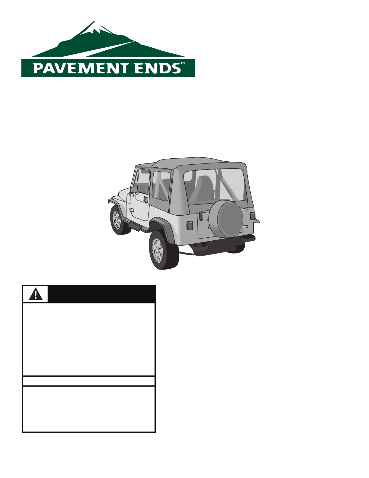
Flip Top with Upper Half Doors
Installation Instructions
www.pavement-ends.com
For: CJ7 1976 - 1986 Part Number: 44583
Wrangler/YJ 1986 - 1995
DO NOT INSTALL THIS PRODUCT ON ANY VEHICLE OTHER THAN THOSE LISTED ABOVE.
WARNING
This product is designed to enhance the appearance of the vehicle and to shield the occupants
from ordinary weather conditions. Do not rely in
any way on the components of this product to
contain occupants within the vehicle, or to protect
against injury or death in the event of an accident.
This product will not protect the occupants from
falling objects. Never operate vehicle in excess of
manufacturer’s specications.
WEAR SEAT BELTS AT ALL TIMES
Read and follow, precisely, all installation instructions provided when installing this product.
Failure to do so may result in a poor t and could
place occupants of the vehicle in a potentially
dangerous situation.
Installation Tips
Before you begin installing this product, read all
instructions thoroughly. Below are a few tips to
make this installation easier. After completing the
installation, keep these instructions for further
reference.
For a smooth t:
For ease in installation, the Flip Top should be
installed at temperatures above 72 ° F. Below this
temperature, the fabric may contract an inch or
more, making it dicult to t to the vehicle.
It is normal for the fabric to contract and wrinkle
when stored in the shipping carton. Within a few
days after the installation, the fabric will relax and
the wrinkles will disappear.
Rev. D 0210
Page 2
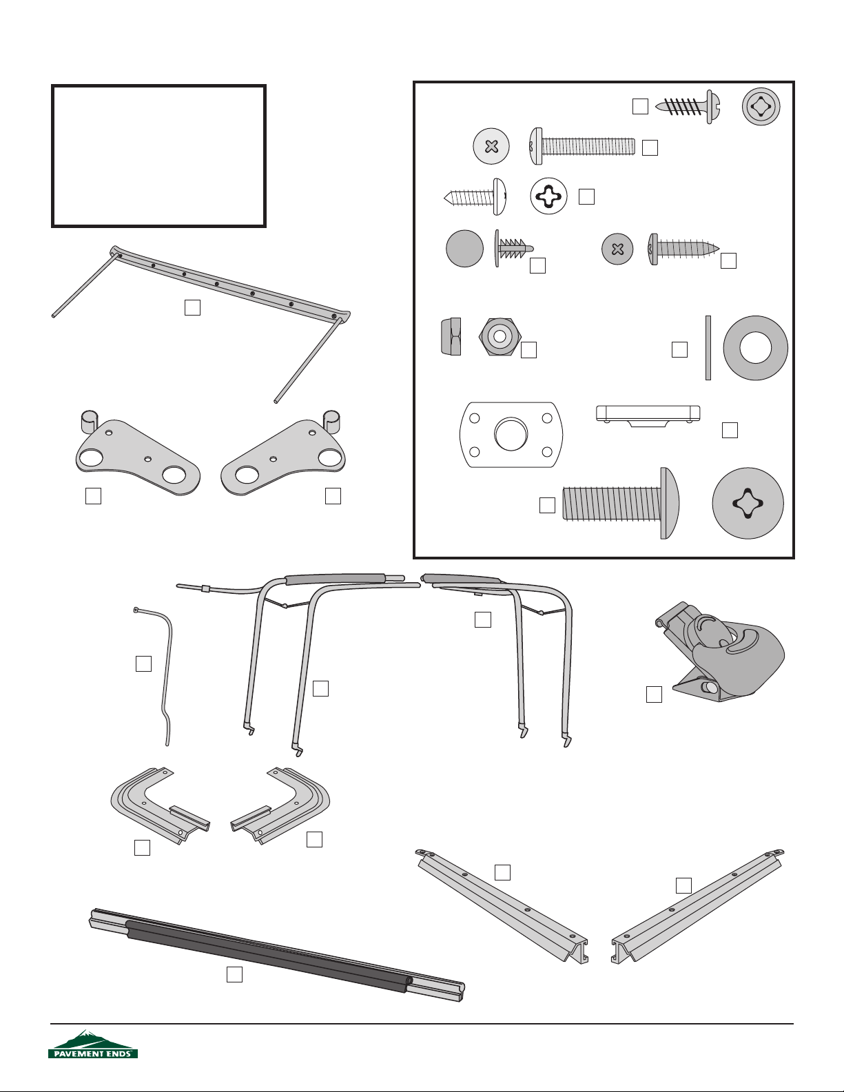
Par ts List and Hardware Identification
Top Fabric Qty - 1
Quarter Window, Rt. Qty - 1
Quarter Window, Lt. Qty - 1
Rear Window Qty - 1
Windshield Header Trim Qty - 1
Left Door Frame Qty - 1
Right Door Frame
Zipper Pull Kit Qty - 1
Windshield Header, Qty - 1,
Part Number 332.72
Qty - 1
#8 x 1/2" Pan Head Washer Screw - Black,
Qty - 2, Part Number 200.48
Christmas Tree Fastener,
Qty - 12, Part Number 332.07
5/16" Black Washer, Qty - 12,
Part Number 233.04
Lock Nut, Qty - 2, Part
Number 316.94
5/16-18 Tapping Plate, Qty - 12, Part
Number 200.50
#10-15/16 Bolt, Qty - 2,
Part Number 326.85
#10 x 1/2"Pan Head Sheet Metal Screw,
Qty - 4, Part Number 1.92
#8 x 5/8" Screw, Qty - 4,
Part Number 278.13
Windshield Bracket - Left, Qty - 1,
Part Number 332.01
Vertical Rod, Qty - 2,
Part Number 134.50
Corner Belt Rail, Left, Qty - 1,
Part Number 288.34
Windshield Bracket - R ight, Qty - 1,
Part Number 332.02
Bow Assembly - Right, Qty - 1,
Part Number 381.34
Bow Assembly - Left, Qty - 1,
Part Number 381.35
Corner Belt Rail, Right, Qty - 1,
Part Number 288.33
5/16-18 x 1" Phillips Head Bolt,
Qty - 12, Part Number 236.20
Side Belt Rail - Left, Qty - 1,
Part Number 134.02
Windshield Header Latch, Qty - 2,
Part Number 326.75
Side Belt Rail - Right, Qty - 1,
Part Number 134.01
Tailgate Bar, Qty - 1,
Part Number 288.75
44583 pg 2
Rev. D 0210
Page 3
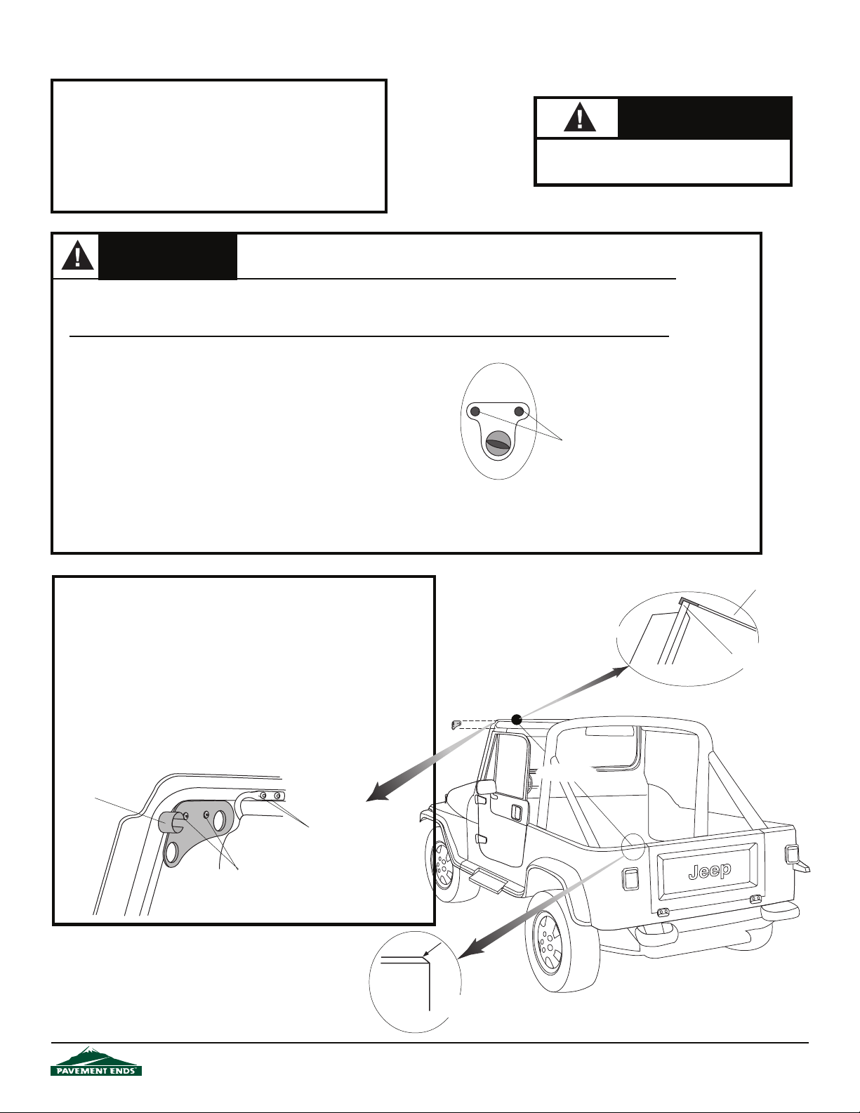
CJ7 Only - Wrangler Adjustment on next page
Tools Needed - CJ7
1/8", 5/32", 3/8" Drill Bit Flat Screwdriver
and Drill Motor Phillips Screwdriver
Center Punch Hammer
#40 Torx - Optional Pencil
t Adjustible WrenchehctaR
Safety Glasses 10' Tape Measure
WARNING
Improper windshield adjustment will result in poor tting top and doors, causing
looseness or undue strain on the top.
Safety glasses should be worn at all
times while installing this product.
Caution
Note: If you are replacing an old soft top, be certain that all parts of the old top are removed, including the windshield
retainer. Old metal parts are not compatible with the new Supertop. Using parts other than those provided in your
Supertop kit can result in personal injury and/or damage to the vehicle and soft top.
Windshield Measurement
Before installing the top, check the windshield measurement.
The distance from the top lip of the windshield to the top outer
edge of the body must be 75 1/8" on both sides of the vehicle.
Measure 4"-6" inside the doors.
CJ7 Windshield Adjustment
If necessary, loosen the two screws in the Windshield Clamps at
the base of the windshield on each side of the vehicle. Adjust the
windshield forward or back, use a shim if needed to position the
windshield, and tighten the screws.
Windshield
Clamp Detail
Adjusting Screws Some Models may
require a #40 Torx
Step One
CJ7: After adjusting the windshield, install the Windshield
Brackets. If present, remove the outboard sun visor fasteners on
both sides of the windshield frame. Place the Windshield
Brackets ush with the frame on the upper corners of the
windshield. Use the bracket as a template to mark, center punch
and drill two 5/32" holes for each bracket. Mount each bracket to
the windshield frame using two #10 x 1/2" Pan Head Sheet Metal
Screws. Reinstall sun visor brackets.
Windshield
Bracket
Sun Visor Mount #20 Torx bolt
#10 x 1/2" Pan Head
Sheet Metal Screws
Tape Measure
Measurement
Detail
Front
Top lip of
windshield
75 1/8"
44583 pg 3
Rear point of
measurement on body
Rev. D 0210
Page 4
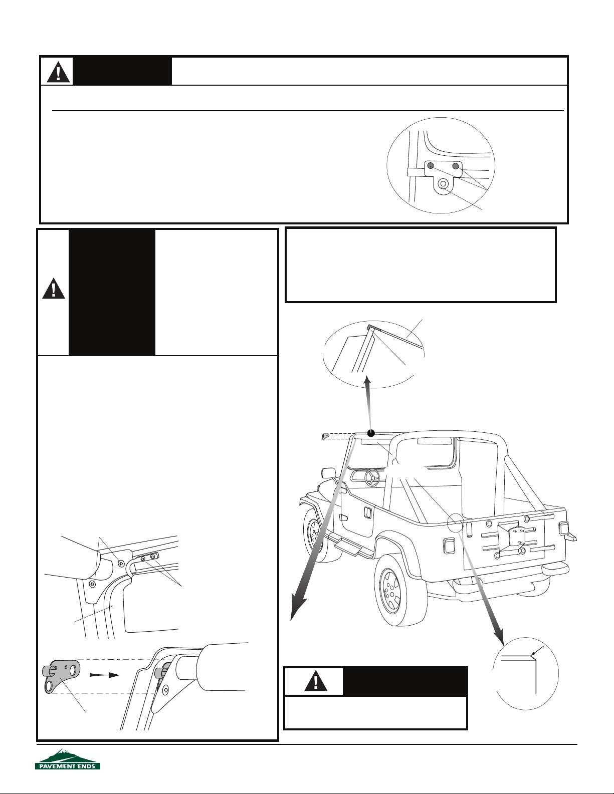
Wrangler Adjustment
WARNING
Note:
Under most circumstances, the windshield of the Wrangler will not require any adjustment. If your Wrangler windshield should require
adjustment, this adjustment should be performed only by an authorized automotive mechanic using a special "Tamper-Proof" Torx head tool.
Improper windshield adjustment will result in poor tting top and doors, causing looseness or
undue strain on the top.
Windshield Measurement
Before installing the top , check the windshield measurement. The distance
from the top lip of the windshield to the top outer edge of the body must be
75 1/8" on both sides of the vehicle. Measure 4"-6" inside the doors.
Wrangler YJ Windshield Adjustment
If necessary, loosen the #40 TORX bolts in the windshield clamps to loosen the
windshield in order to slip the bracket under the horizontal tube.
Reinstall the bolts that secure the
WARNING
Horizontal Sport Bars to the windshield with a torque of 17.0 ft. lbs.
each. If you do not have a torque
wrench these bolts should be
tested by a qualied mechanic
using a torque wrench. Failure to
tighten and test the torque of
these bolts can result in personal
injury or loss of life to the driver
and occupants of the vehicle in
the event of an accident.
1/8", 7/32", 3/8" Drill Bit #35 Torx - Optional Phillips Screwdriver
and Drill Moto #40 Torx - Optional Hammer
Center Punch #45 Torx - Optional Adjustable Wrench
Pencil Flat Screwdriver Ratchet
#20 Torx - Optional 10' Tape Measure Safety Glasses
Measurement
Detail
Step One
Tools Needed- Wrangler
Tape Measure
Front
Top lip of
windshield
#40 TORX Bolts
#45 TORX Bolt
Wrangler/YJ: Use a #20 Torx to remove the outboard sun visor
fasteners on both sides of the windshield frame. Remove the
two #40 Torx head bolts that secure the horizontal sport bar to
the windshield frame. Slide the Windshield Brackets between
the windshield and the horizontal sport bar mounts.
Reinstall the Torx head bolts, starting each in the frame with
your ngers. After the Torx head bolts are started by hand,
tighten with your rachet and Torx drive tool. Do not lay this
tool aside until both bolts are completely tightened. If you
tighten one of these bolts and the telephone rings - LET IT RING.
NEVER LAY THIS TOOL ASIDE OR INTERRUPT THIS PROCEDURE. This procedure should be followed carefully on both
sides of the vehicle.
Remove #40 TORX Bolts
Horizontal Sport
Bar
Sun Visor Mount #20 Torx bolt
Windshield
Windshield
Bracket
Sun Visor
Slide Windshield
Bracket between
Windshield and the
Sport Bar Mount
75 1/8"
Caution
Safety glasses should be worn at all
times while installing this product.
Rear point of
measurement on
body
44583 pg 4
Rev. D 0 2 1 0
Page 5
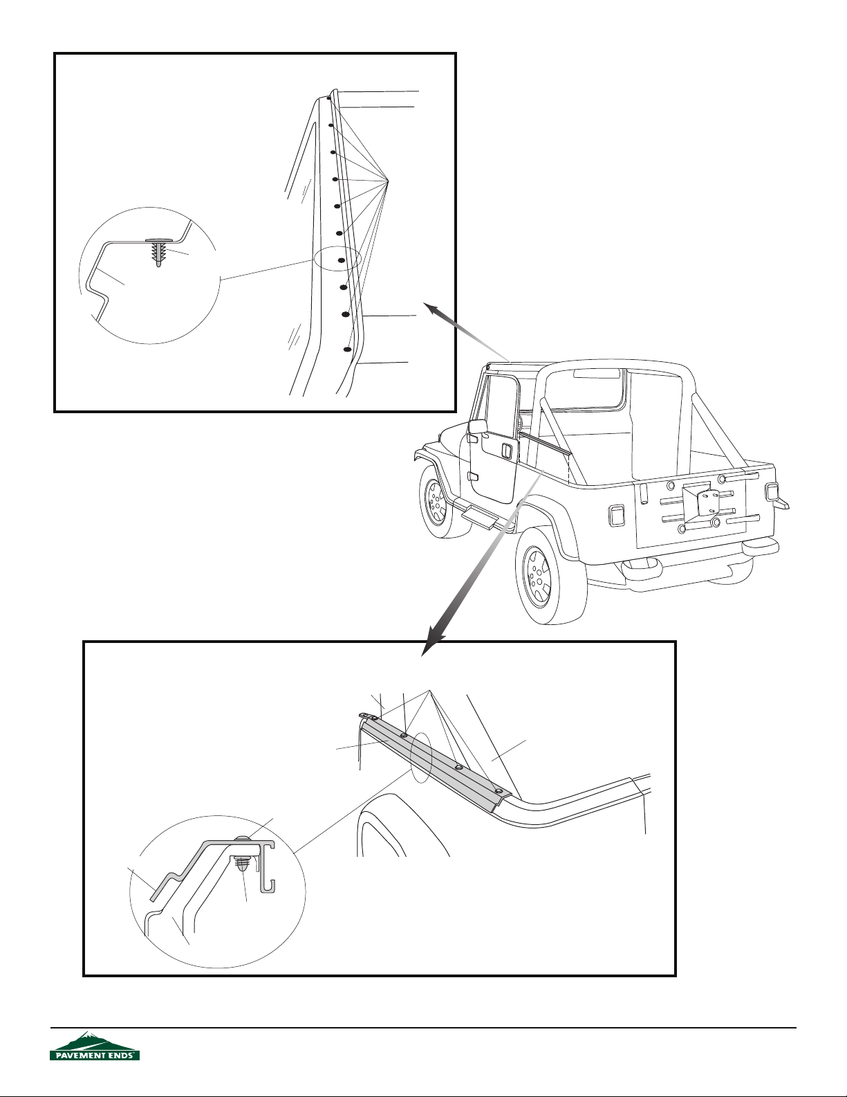
Step Two
INSTALL CHRISTMAS TREE FASTENER
If you have removed an old Bestop
top and windshield retainer, install a
Christmas Tree Fastener in each hole
in the windshield frame.
Christmas Tree Detail
Cross Section
Front of Vehicle
Christmas Tree
Fastener
Windshield Frame
Front of
Vehicle
Christmas
Tree Fasteners
Windshield
Step Three
INSTALL BELT RAILS
Install the Left and Right Side Belt
Rails on each side of the vehicle. Use
the existing holes, four 5/16" TORX
Bolts and four Tapping Plates on each
side. Use a #35 TORX Socket to install
the TORX Bolts.
Side Belt Rail Detail
Cross Section
Side Belt Rail
Tapping Plate
Inside of Vehicle
Body Panel
44583 pg 5
5/16" TORX
Bolt
Sport Bar
Front
Side Belt
Rail
5/16" TORX Bolt
Sport Bar
Rev. D 0210
Page 6
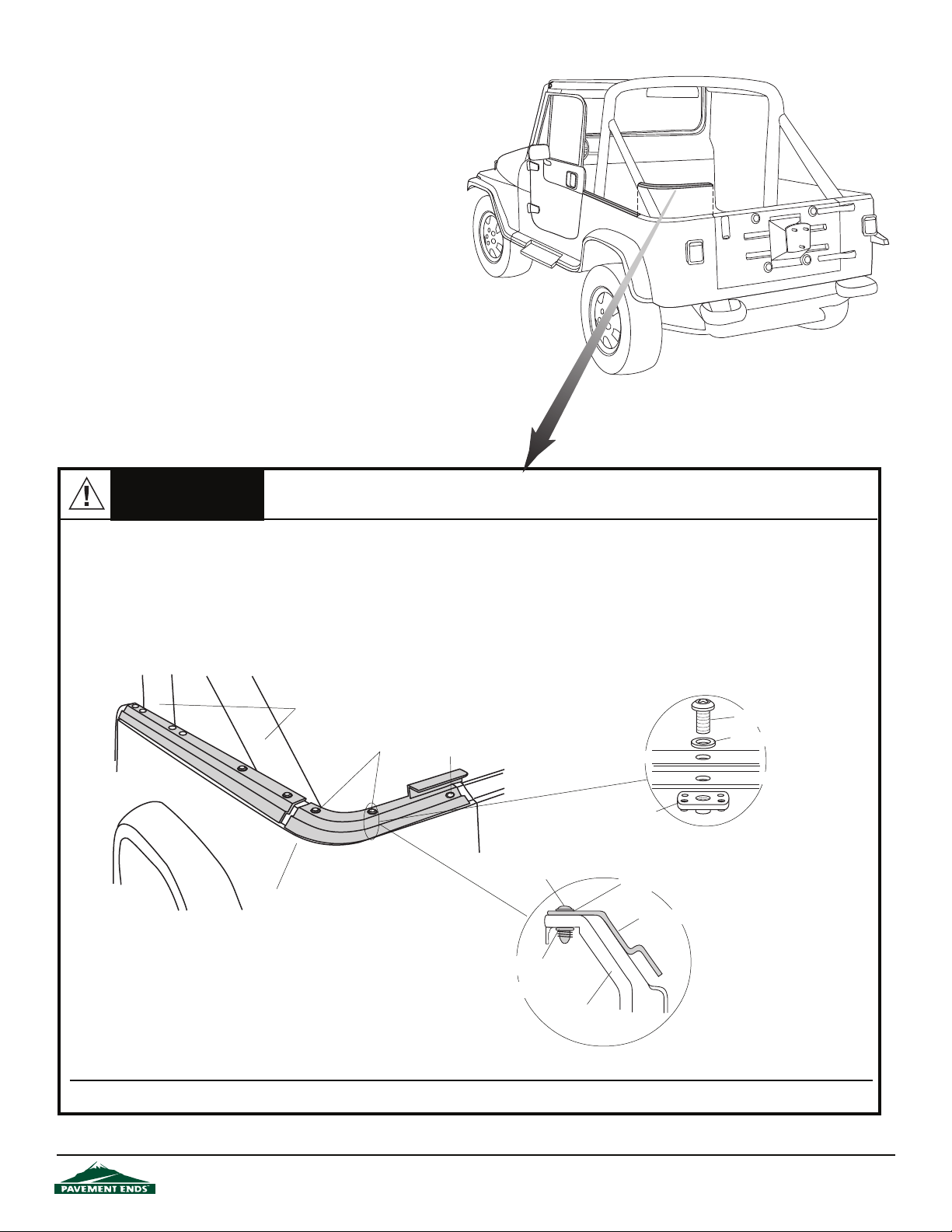
Caution
When drilling in the top edge of the vehicle body, check underneath for wiring for the rear lights. Pull the
wiring out of the way before drilling.
Step Four
INSTALL THE CORNER BELT RAILS
Install the Left and Right Rear Corner Belt Rails on each side of the vehicle. Notice that the Corner Belt Rails do not butt-up against the Side
Belt Rails installed in Step 3, this is normal. Use the Corner Belt Rails as templates to mark, center punch and drill two 3/8” holes in the top edge
of the vehicle body. Some vehicles may already have some of these holes. Install the Corner Belt Rails with two 5/16” Phillips Head Bolts, two
5/16” Washers and two 5/16" Tapping Plates. At the location of the remaining hole in the Corner Belt Rail, next to the tailgate, mark, center punch
and drill a 1/8" hole. Install a #8 x 1/2" Pan Head Screw. Do not tighten the bolts yet.
Tapping Plate
Detail
Corner Belt
Rail
Tapping Plate
5/16" Washer
Rear Corner
Belt Rail
Body Panel
Front
Sport Bars
Rear Corner
Belt Rail
5/16" Phillips
Head Bolts
#8 x 1/2" Pan
Head Screw
5/16" Phillips
Head Bolt
Tapping Plate
Inside of Vehicle
Rear Corner Belt Rail Detail
Cross Section
Note: There may be a small gap of +/- 1/4" between the Corner Belt Rails and the Side Belt Rails.
5/16" Phillips Head Bolt
5/16" Washer
Vehicle Body
44583 pg 6
Rev. D 0210
Page 7
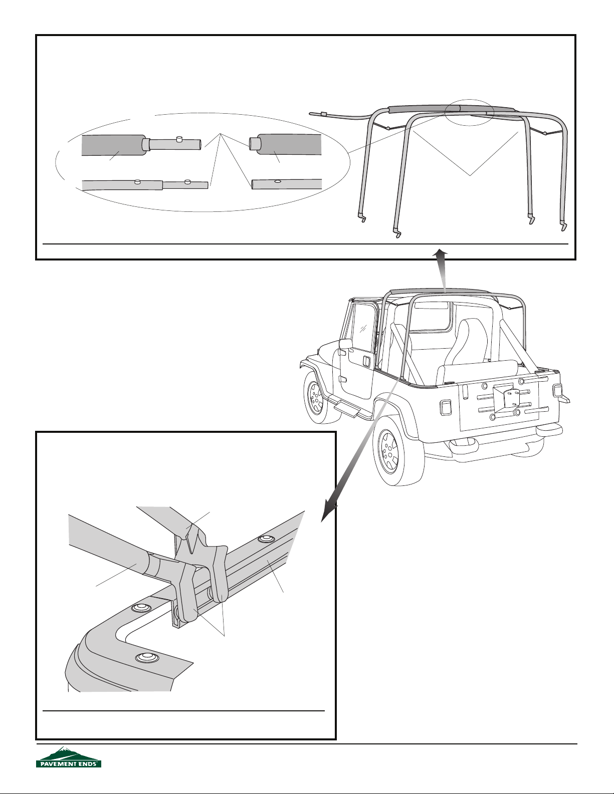
Step Five
ASSMEBLE BOW ASSEMBLY
Assemble the two halves of the support bow. Orient the two pieces to each other and lay them on the oor. Slide the pieces together, pushing
down on the buttons. Once the two halves are together install a Snap Head Screw in the hole formed in the center, front of each bow. This
will require a #20 TORX socket.
Push buttons in
Front Bow
Slide Bow Halves
Together
Foam
Rear Bow
Foam
Slide halves together to form
Support Bow Assembly
Note: It may be helpful to use a at screwdriver to push buttons down while sliding bow halves together.
Step Six
INSTALL BOW ASSEMBLY
Slide the ends of the front and rear bows into the tracks in the Side Belt Rails
on each side of the vehicle. Start from the rear of the vehicle and slide the bow
assembly toward the front.
Front Bow
Rear Bow
Slide Bow Ends
into Track
Note:
It may be helpful to have two people to slide both sides of the bow
assembly forward at the same time.
44583 pg 7
Side Belt Rail
Inside of Vehicle
Rev. D 0210
Page 8
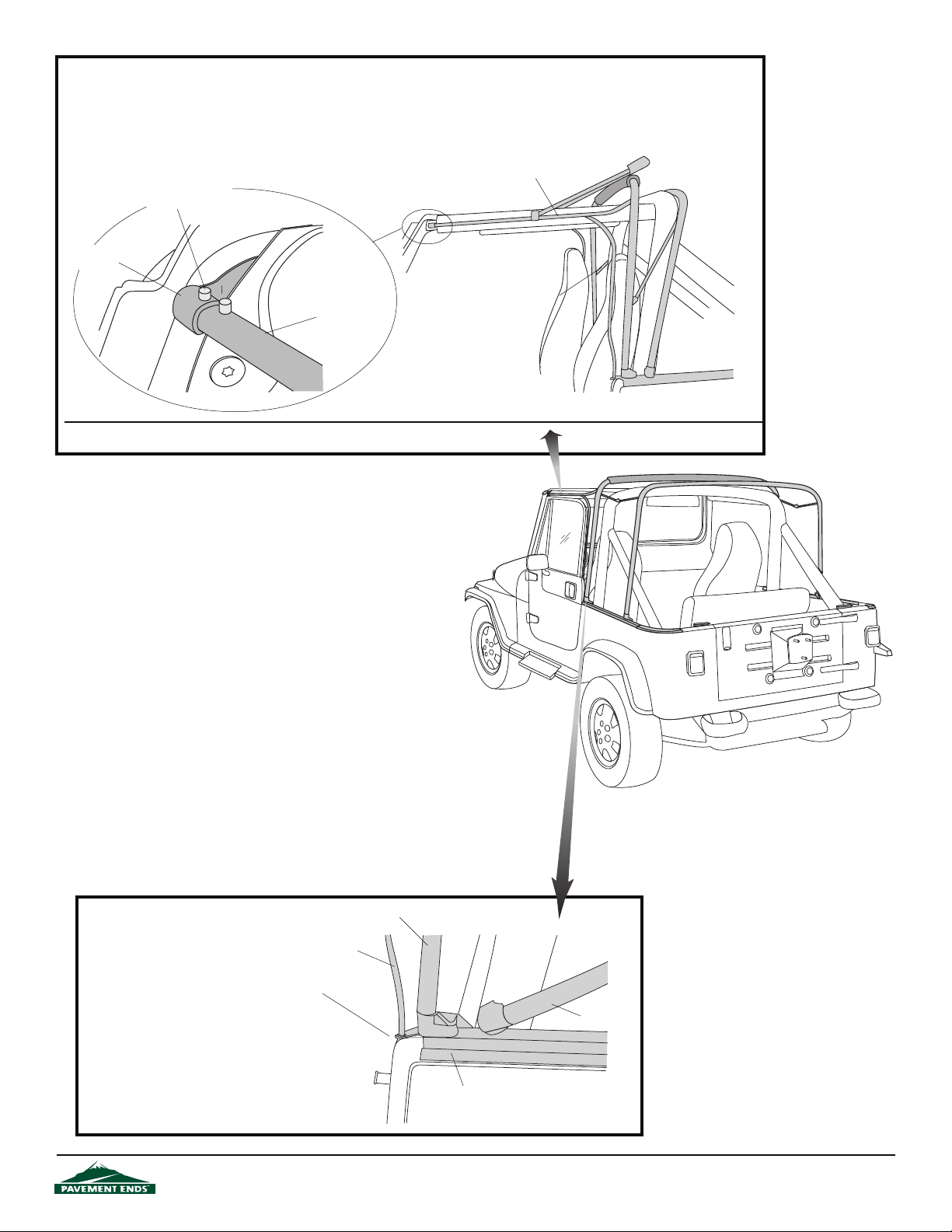
Step Seven
INSTALL HORIZONTAL ROD
Slip the end of the Horizontal Rod into the tube on the Windshield Bracket until the spring button on the rod pops up
through the hole in the Windshield Bracket.
Horizontal Rod
Slide rod into bracket
until pin pops up
Windshield
Bracket
Vertical Rod
Horizontal Rod
Note: The pin must pop up through the hole in the Windshield Bracket for proper t.
Step Eight
INSTALL VERTICAL ROD
Place the bottom of the Vertical
Rod into the hole at the front of
the Side Belt Rail. Bolt the rod
to the Horizontal Rod on the
Bow Assembly with the Screw
and Nut attached to the
Horizontal Rod.
44583 pg 8
Vertical Rod
Place Vertical Rod
into hole
Front Bow
Rear Bow
Side Belt Rail
Rev. D 0210
Page 9
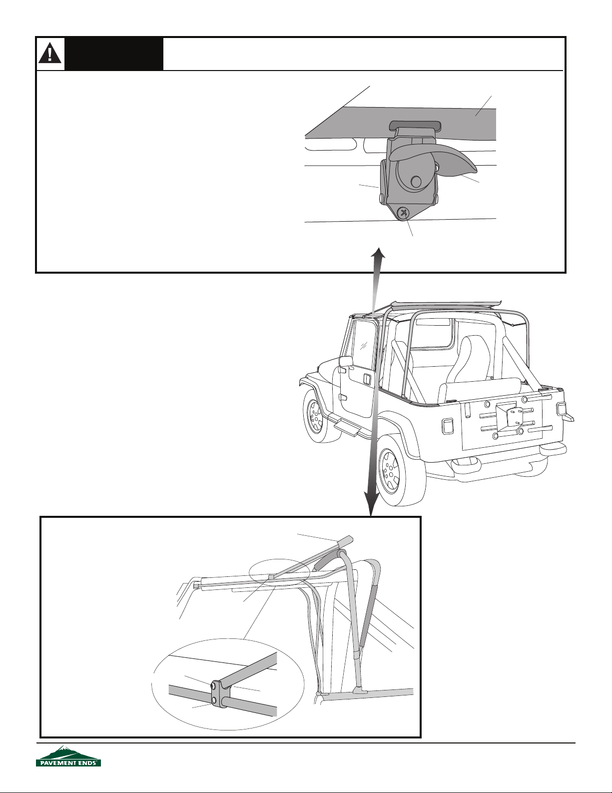
WARNING
Improper Latch installation will result in a poor tting Header that could rattle or release under driving
conditions.
Step Nine
INSTALL WINDSHIELD HEADER LATCH
Rotate the Windshield Header down onto the top of the windshield.
Locate the two Windshield Header Latches in the parts kit. Make
sure that the latches are in the closed position. Hook each latch
in the slots in the Windshield Header. Pull Header down at on
the windshield. Pop the lever out into the horizontal position and
mark the location of the bottom hole in the latch. Remove the
latch from the slot and spring the body of the latch out so that it
is horizontal to the base and so that you can access the top
mounting hole. Place the latch back in position with the bottom
hole over the mark on the windshield and mark the location of
the top hole. Remove the latch, center punch the marks and drill
two 1/8" holes per latch in the windshield frame. Install each
latch with two #8 x 5/8" Screws.
Horizontal
Sport Bar
Windshield Header Latch
Windshield Frame
Windshield Header
Lever (Horizontal Position)
#8 x 5/8" Screw
Step Ten
INSTALL WINDSHIELD HEADER
Orient the Windshield Header on
the vehicle. Lay the header on
top of the bows with the snap
studs facing up. Place the legs
of the header into the bracket
above the door opening on each
horizontal rod. Install the legs in
the brackets with a #10-15/16
Bolt and Lock Nut on each side.
Front
44583 pg 9
Windshield
Header
Bracket
#10-15/16
Bolt
Lock Nut
Bracket
Rev. D 0210
Page 10
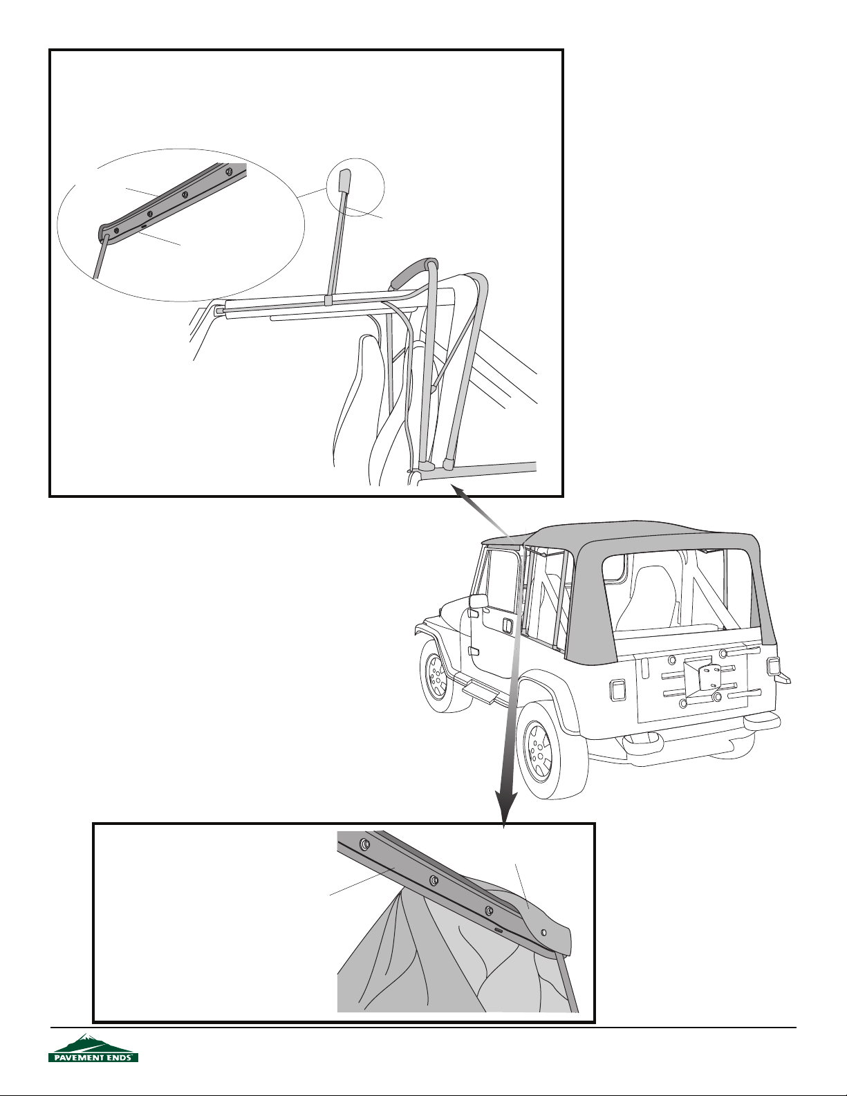
Step Eleven
INSTALL WINDSHIELD HEADER TRIM
Open the latches and raise the Windshield Header. Locate the rubber Windshield Header Trim in
the parts kit. Slide the slotted edge of the trim over the front edge of the Windshield Header. Trim
to t.
Windshield
Header Trim
Windshield Header
Windshield
Header
Step Twelve
INSTALL TOP TO HEADER
Locate the top and orient it on the
vehicle. Drape the top over the
bows and wrap the front edge of
the fabric around the front edge
of the Windshield Header. Snap
the fabric to the header.
44583 pg 10
Wrap fabric around and
snap to Windshield Header
Windshield
Header
Rev. D 0210
Page 11
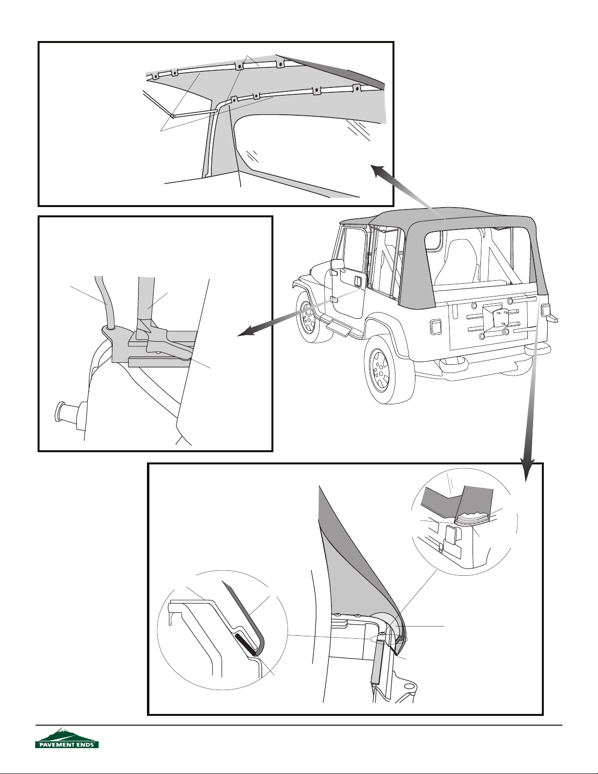
Step Thirteen
SNAP TOP TO BOWS
Locate the top and and
orient it on the vehicle.
Snap it to bows.
Snap to bows
Step Fourteen
POSITION FRONT BOW
Push the front support bow all the way forward.
slip into notch in belt rail.
Vertical
Rod
Front Support
Bow
Bows
View from inside top
The bow must
Front
Bow must slip into
notch in belt rail
Sport Bar
Step Fifteen
SECURE REAR CORNERS
Insert the rear corners of the top into
the Rear Corner Retainers.
Rear Corner
Retainer
Fabric
Edge of Plastic Strip
must line up with
edge of retainer
Rear Corner
Retainer
Plastic Strip under retainer
Plastic Reinforcement not
caught under retainer
44583 pg 11
Plastic Strip
Plastic Strip
under retainer
Rear of Vehicle
Rev. D 0210
Page 12
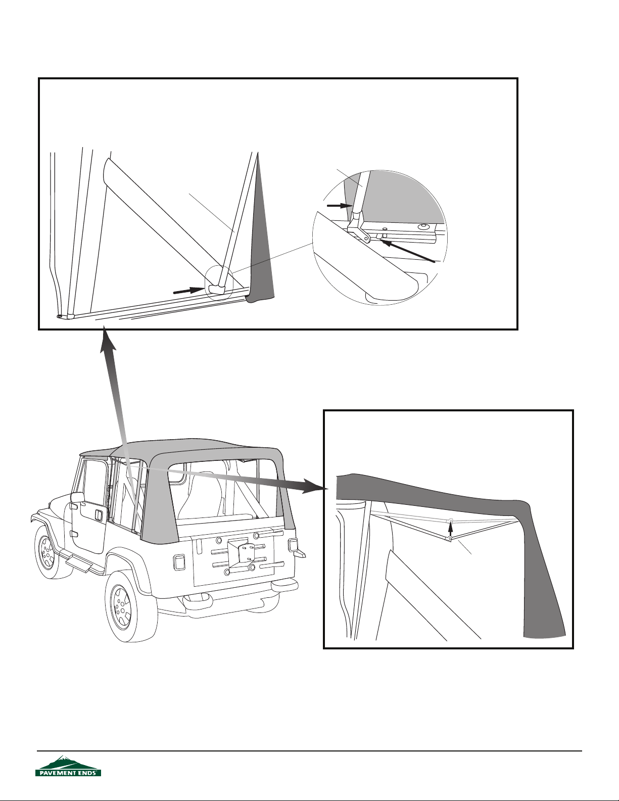
Step Sixteen
POSITION REAR SUPPORT BOW
Pull the bottom of the rear support bow back until it snaps into the notch in the side rail. Make sure that the zippers are not
caught or folded behind rear support bow and that the bow slips into the notch in the Side Belt Rail.
Rear Support Bow
Rear Support Bow
Push bow back
Bow must slip into
notch in belt rail
View from inside vehicle
Step Seventeen
POSITION SPREADER BARS
Push the spreader bars up until they snap into place.
Spreader Bar
44583 pg 12
Rev. D 0210
Page 13
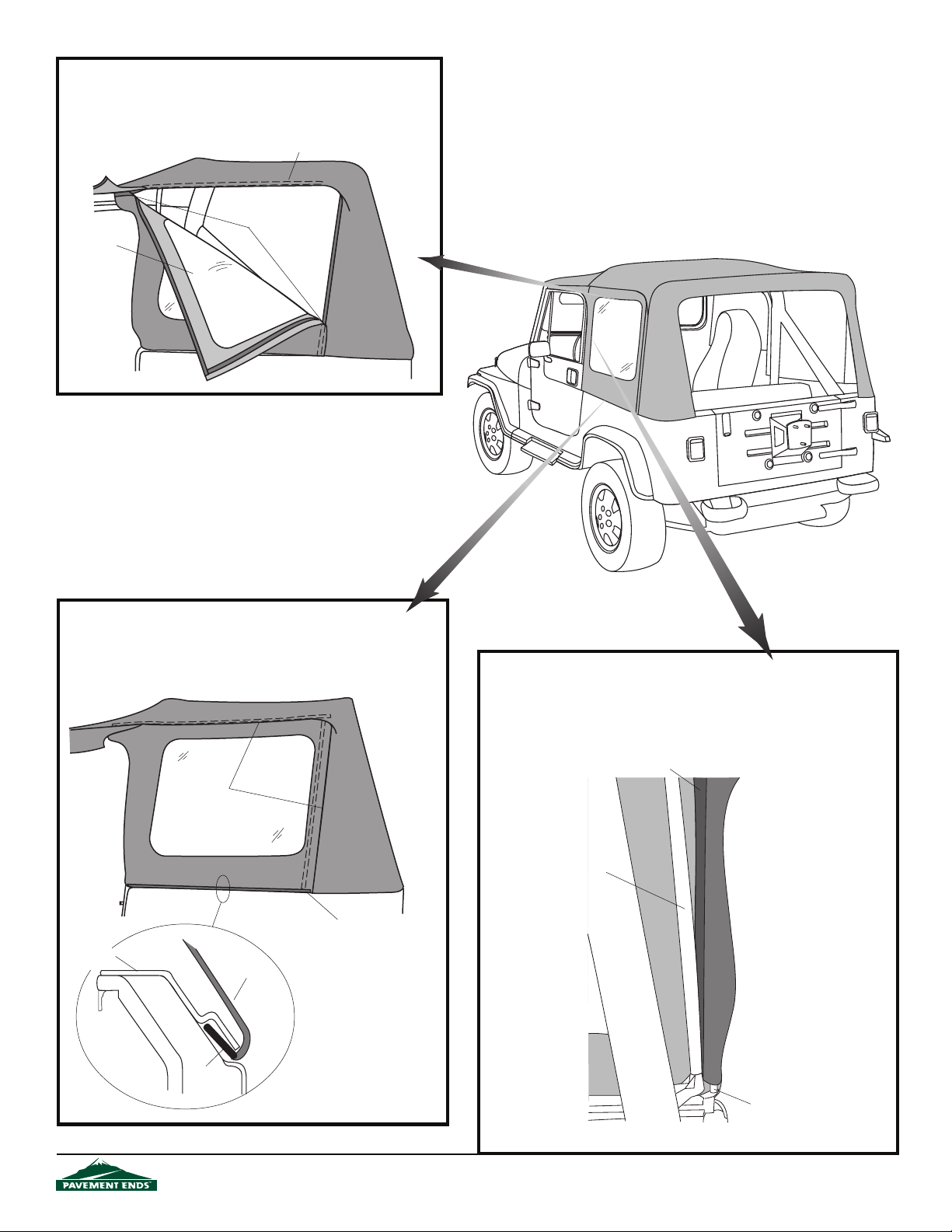
Step Eighteen
INSTALL QUARTER WINDOWS
Start the top and rear zippers on the Quarter Windows 2-3 inches.
Zipper under ap
Start top and
Quarter
Window
rear zippers
Step Nineteen
INSTALL Q
Slip the plastic strip on the bottom of the Quarter Window into the
Side Belt Rail. Close the top and rear zippers on the side curtain.
Side Belt
Rail
UARTER
WINDOWS
Close Zippers
Fabric
Start at one end of
the strip and work
along it to the
other end.
Step Twenty
INSTALL QUARTER WINDOWS
Wrap fabric ap on the front of the side curtain around the Vertical Rod
(not the front bow) and fasten the hook and loop strips to each other.
Hook and Loop Fastener
Front Bow
Front
Sport Bar
Plastic
Strip
44583 pg 13
Vertical
Retainer
View from inside vehicle - Driver's Side
Rev. D 0210
Page 14
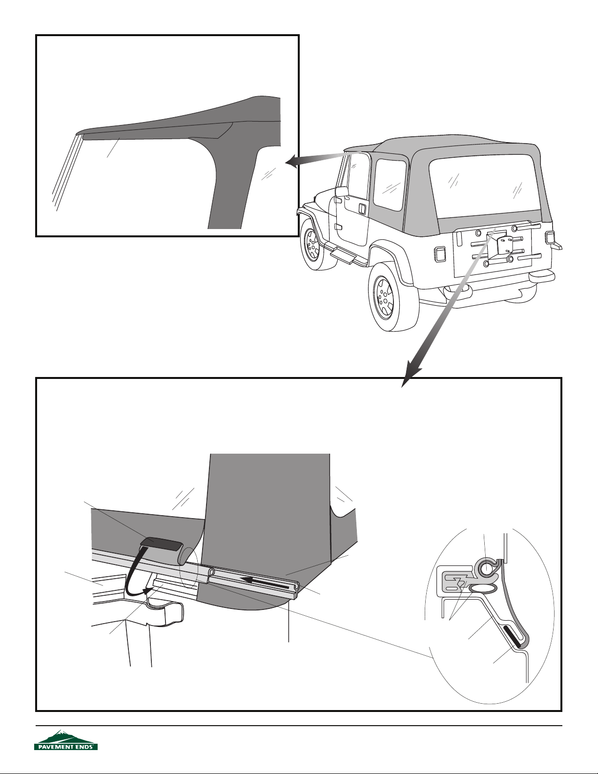
Step Twenty-one
SECURE DOOR OPENING
Wrap the ap, sewn to the top above each door, around the Horizontal
Rod and fasten the hook and loop strips to each other.
Front
Wrap Flap around
Horizontal Retainer
Windshield
Step Twenty-two
INSTALL TAILGATE BAR
Open the tailgate. Orient the Rear Curtain Retainer with the rubber bulb facing down, in order to form a seal with the top of the tailgate. Slide the
groove in the Rear Curtain Retainer onto the tube inside the bottom of the Rear Curtain. Roll the Rear Curtain Retainer into the top of the Corner
Belt Rail. Slip the plastic on the bottom of the corners under the bottom of the Corner Belt Rail. Close the rear curtain zipper.
Slip Plastic Strip under
Corner Retainer
TAILGATE MUST
BE OPEN
Rear Corner
Retainer
44583 pg 14
Rear Curtain
Rear Curtain Retainer
Slide groove in Rear Curtain
Retainer onto tube on inside
of Rear Curtain. Push it into
Tailgate Retainer.
Rear Curtain Retainer Oriented with Rubber
Bulb Down
Tube on inside of
Rear Curtain
Rear Corner
Retainer
Plastic
Strip
Rev. D 0210
Page 15
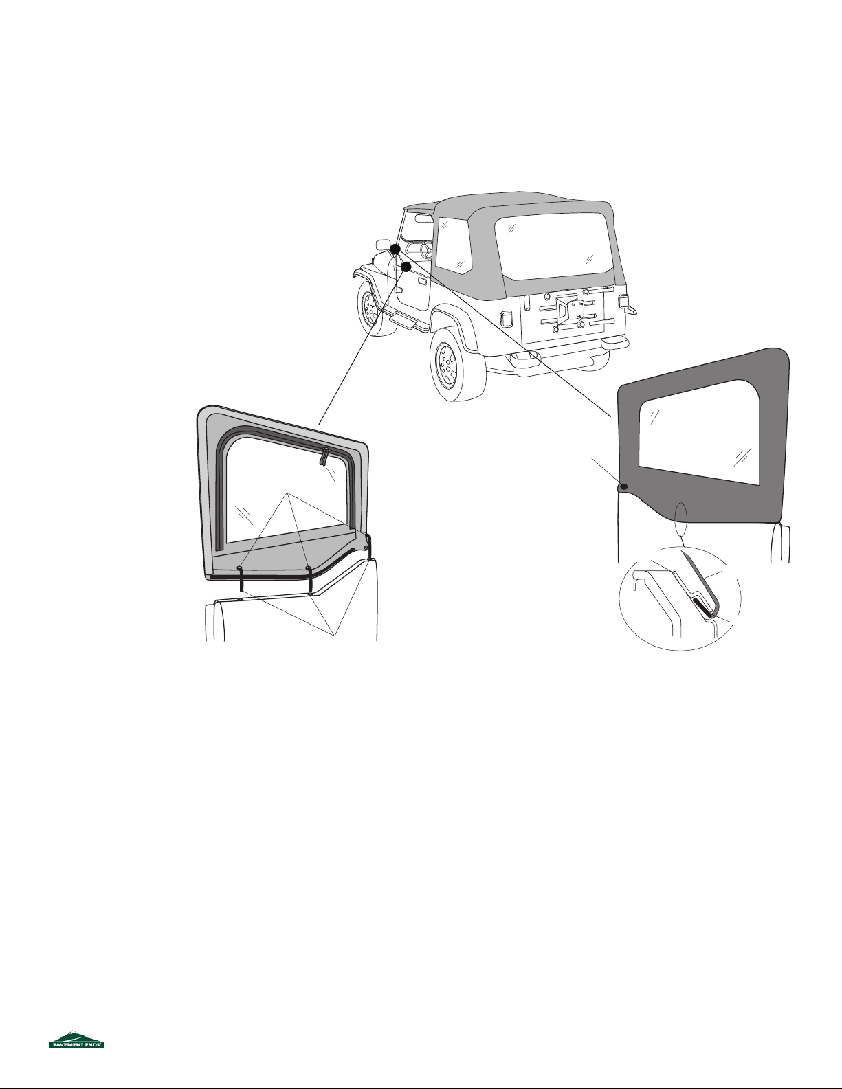
44583 pg 15
Rev . D 0210
ANY
Door
Retainer
Step Twenty-ve
Fasten the snap at front of upper
door. Slip plastic strip on the
bottom of the soft door into the
retainer on the steel door.
Plastic Strip
Snap to Door
Pins
Grommets
Step Twenty-four
Reinstall the upper doors.
Insert the pins into the
grommets in the lower
door.
Fabric
Step Twenty-three
Separate the hook and loop fasteners on the
and slide the new cover onto the frame, starting at the
top. Work from corner to corner, wrapping
around the frame and fastening the hook to
you work around the door.
door covers
the fabric
the loop as
Page 16
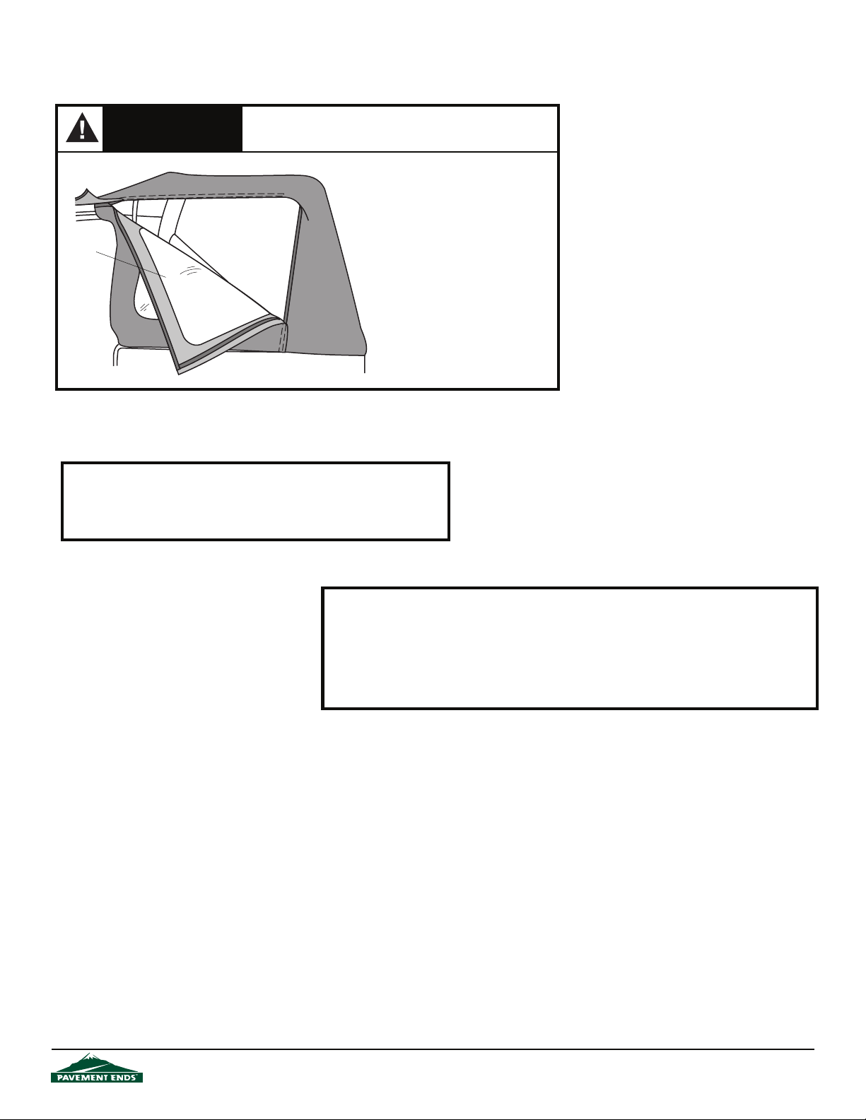
Adjusting the Top
WARNING
When operating the vehicle without the Quarter Windows,
the Rear Curtain should be rolled up for proper ventilation.
Quarter Windows
Quarter
Window
To remove the Quarter Windows.
Unzip the rear and top zippers.
Release the plastic strip from the
retainer. Release the Hook and
Loop Fasteners from around the
Vertical Retainer.
Opening the Sun Roof
Release the Windshield Header Latches and fold the Windshield Retainer
back so that it rests on the center bow and the sport bar.
Removal of Soft Top for Open Air Driving
When operating the vehicle with the fabric top removed, it is very important that the supporting hardware system be disconnected from the windshield bracket and folded at to the rear
of the vehicle. Wrap the elastic straps around the bows and insert the plastic strip into the
Side Belt Rail. Never operate the vehicle with the fabric removed and the hardware in the fully
erected position.
44583 pg 16
Rev. D 0210
Page 17
Care and Maintenance of your Flip Top
Your top is made of the nest materials available. To keep it looking new and for the maximum possible wear, it will need periodic cleaning and maintenance.
Washing: The top fabric should be washed often using soap, warm water and a soft bristle
brush. Rinse with clear water to remove all traces of soap.
Windows: Keep windows clean to avoid scratching. DO NOT use a brush on the windows!
Wash with a watersoaked cloth or sponge and a mild dishwashing detergent. NEVER WIPE
THE WINDOWS WHEN THEY ARE DRY. Be careful when cleaning snow or frost from the vinyl
windows since they are easily scratched and may crack at low temperatures. DO NOT roll the
sides or rear window in cold weather. The windows become sti and will crack.
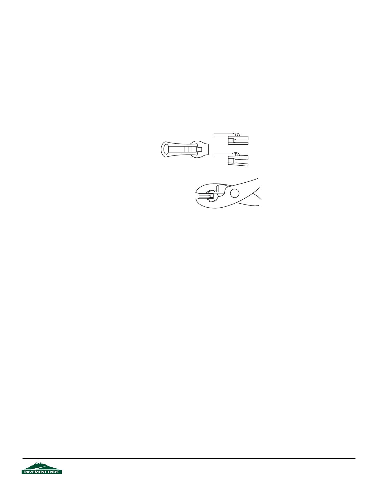
Zippers: Keeping the zipper cleaned and lubricated with a silicone lubricant will help prevent
damage and keep the zippers in a smooth working condition. If a zipper opens behind the
slider, the slider may have been spread apart.
This problem can usually be
repaired by using an ordinary
pair of pliers to bring the sides
back into parallel. Return slider
to the end of the zipper in the
normal Open position. Squeeze lightly at rst
and test the zipper. If the zipper continues to
remain open squeeze more rmly with the
pliers and try the zipper again. Repeat this
procedure until the zipper operates correctly.
Water: Seeping through at the seams may be
stopped by applying 3-M Scotchgard® on the
inside of the seams. Rips in the fabric may be repaired with Bondex® iron on patches. Iron
the patches to the Inside of the top, carefully following the Bondex® instructions.
Snaps: Keep snaps cleaned and lubricated with silicone to help prevent snaps from sticking to
the studs. If a snap does become stuck to a stud, use a screwdriver and GENTLY pry apart to
prevent permanent damage to the snap or the top fabric.
Normal Slider Jaws Parallel
Damaged Slider Jaws Spread Apart
(sometimes broken)
LIMITED WARRANTY
We warrant our product to be free from defects in material and workmanship, for the terms specied below, provided there has been normal use and
proper maintenance. This warranty applies to the original purchaser only. All remedies under this warranty are limited to the repair or replacement of
any item or items found by the factory to be defective within the time period specied.
If you have a warranty claim, rst you must call our factory at the number below for instructions. You must retain proof of purchase and submit a copy
with any items returned for warranty work. Upon completion of warranty work, if any, we will return the repaired or replaced items or items to you freight
prepaid. Damage to our products caused by accidents, re, vandalism, negligence, misinstallation, misuse, Acts of God, or by defective parts not
manufactured by us, is not covered under this warranty.
THE WARRANTY TIME PERIOD IS AS FOLLOWS: ALL “SOFT GOODS” MANUFACTURED BY OUR COMPANY (USING PRIMARILY VINYLS, PLASTICS,
AND/OR FOAM): ONE YEAR FROM DATE OF PURCHASE.
ANY IMPLIED WARRANTIES OF MERCHANTABILITY AND/OR FITNESS FOR A PARTICULAR PURPOSE CREATED HEREBY ARE LIMITED IN DURATION
TO THE SAME DURATION AND SCOPE AS THE EXPRESS WRITTEN WARRANTY. OUR COMPANY SHALL NOT BE LIABLE FOR ANY INCIDENTAL OR
CONSEQUENTIAL DAMAGE.
Some states do not allow limitations on how long an implied warranty lasts, or the exclusion or limitation of incidental or consiquential damages, so the
above limitations or exclusions may not apply to you.
This warranty gives you specic legal rights, and you may also have other rights which vary from state to state.
For further information or request for warranty work, please contact: Customer Service
(877)638-9509
All or a portion of this product may have been produced in China.
44583 pg 17
Rev. D 0210
 Loading...