

Pavailler TOPAZE Series, TOPAZE C04B, TOPAZE L10B, TOPAZE C10B, TOPAZE L04B User & Installation Manual
Use
r
/Installation manual
Translated manual
TOPAZE STYLE OVEN
Language: ENGLISH
Code: 20045080-05
Date: 04/2013

Ladies and gentlemen,
You have just purchased one of our Pavailler products.
We wish to thank you for the confidence you have placed in our products.
These products are the result of extensive studies and testing to ensure your full satisfaction.
Our sales and after sales teams are always available to help you install, start up and use the product under
optimum conditions.
WARRANTY CONDITIONS ON THE FRENCH MARKET
This document contains the conditions and recommendations for installing, using and maintaining our
equipment.
Pavailler equipment has a one year warranty for parts and labour.
Certain operations requiring the intervention of a specialised technician may only be performed by Pavailler’s
after sales service or one of our authorised dealers.
Any modifications to the equipment and non-observance of the recommendations of use stated above shall
release Pavailler from all liability and make the warranty null and void.
For further information, please contact our technicians or authorised dealers.
In a continuous quest for improvements S.E.B.P. reserves the right to modify the technical characteristics of
its products without prior notice. Dimensions, visuals and weights are given by way of illustration.
PLEASE READ CAREFULLY BEFORE USING THE EQUIPMENT
o The customer must make sure that the premises where the equipment is to be installed have a
suitable capacity, in compliance with the applicable rules and standards.
o There must be no flour accumulations in the vicinity of the oven.
Flour, the main ingredient in dough, is also considered the main cause of respiratory diseases in the baking
sector, such as colds and asthma.
In fact, dust developing during flour processing are one of the causes for different forms of colds or, more
seriously, different types of asthma.
Below is a list of recommendations on how to limit flour dust formation in the bakery as much as possible:
• Use 25 kg bags instead of 50 kg bags and empty them in several steps.
• Place the open end of the bag on the bottom of the mixer bowl and pull it up gently, holding the other end.
• Reduce the height from which the flour drops as much as possible.
• Do not shake the empty bag, close it and gently roll it up to fold it.
• Add the flour into the mixer bowl after the water (never the other way round).
• Distribute the flour manually or by means of a sieve without throwing it.
• Clean the worktop with the dough cutter, do not use a brush or compressed air (air gun).
• Separate work clothes from normal clothes.
• Do not shake out or brush work clothes, wash them.
• Avoid draughts.
• When using the mixer stick to the programmed operation in first gear during the first two minutes of the
mixing cycle.
This is when the most flour dust is emitted.
• When using the mixer shift back into first gear each time flour is added.
• It is preferable to use a vacuum cleaner with a dust filter and to perform the cleaning operations in damp
conditions by using a scraper instead of brushes or rags.
• Wear a protective mask during the operations generating the most dust: loading the mixer bowl, using the
hydraulic divider, flouring the dough pieces, etc.
• Use equipment specially designed for reducing dust emissions: mixer with anti-dust lid, hydraulic divider
with anti-adhesion treatment, etc.
Other volatile substances can be harmful or dangerous to the operator’s health, please consult the
information given by the raw material supplier.
In compliance with the current regulations this symbol indicates that the product may not be
disposed of with household waste at the end of its service life.
To protect the environment the product must be taken to a collection point suitable for its
treatment, valorisation and recycling.
The user thus helps to preserve natural resources and to protect health.
LIMITING FLOUR DUST EMISSIONS
ENVIRONMENTAL PROTECTION

CONTENTS
1 GENERAL CHARACTERISTICS..................................................................................4
1.1 DESCRIPTION 4
1.2 OVERALL DIMENSIONS OF TOPAZE STYLE OVENS 5
1.3 DIMENSIONS AND WEIGHT 6
1.4 POWER AND INTENSITY TABLE 6
1.5 OPTIONS AND ACCESSORIES 6
1.6 CONFORMITY OF REGULATIONS 7
1.7 ACOUSTIC CHARACTERISTIC 7
1.8 INSTRUCTIONS OF RECYCLING 7
2 INSTALLATION AND COMMISSIONING.....................................................................9
2.1 INSTALLATION 9
2.2 START-UP 12
3 UTILISATION ET MODE D'EMPLOI.............................................................................13
3.1 ELECTROMECHANICAL CONTROL PANEL 13
3.2 ELECTRONIC CONTROL PANEL 15
3.3 COOKING 25
3.4 CLEANING OF THE OVEN 27
3.5 POSITION OF SLIDERS FOR BACKING PANS 27
4 MAINTENANCE.............................................................................................................28
5 WIRING DIAGRAMS .....................................................................................................29
5.1 SETTING THE BREAKER MOTOR Q2 29
5.2 ELECTROMECHANICAL CONTROL TOPAZE L04B-C04B 30
5.3 ELECTROMECHANICAL CONTROL : TOPAZE L10B-C10B 32
5.4 ELECTRONIC CONTROL : TOPAZE L04B-C04B 34
5.5 ELECTRONIC CONTROL: TOPAZE L10B-C10B 36
6 PARTS LIST...................................................................................................................38
6.1 GENERAL PARTS LIST FOR L04B AND C04B : 38
6.2 GENERAL PARTS LIST FOR L10B ET C10B 40
6.3 DOOR OF TOPAZE L04B AND C04B 42
6.4 DOOR OF TOPAZE L10B AND C10B 44
6.5 OURA VALVE (ELECTRONIC MODEL) 46
6.6 POSITIONING OF PROBES 47
6.7 ELECTRIC PART FOR TOPAZE L04B-C04B ELECTRONIC 50
6.8 PARTS LIST FOR ELECTRIC PART L10B-C10B ELECTROMECHANICAL 52
6.9 PARTS LIST FOR ELECTRIC PART L10B-C10B ELECTRONIC 54
6.10 PARTS LIST ENGINE AND SLOG 56

TOPAZE STYLE OVEN Translated manual N°20045080-05
1 GENERAL CHARACTERISTICS
1.1 DESCRIPTION
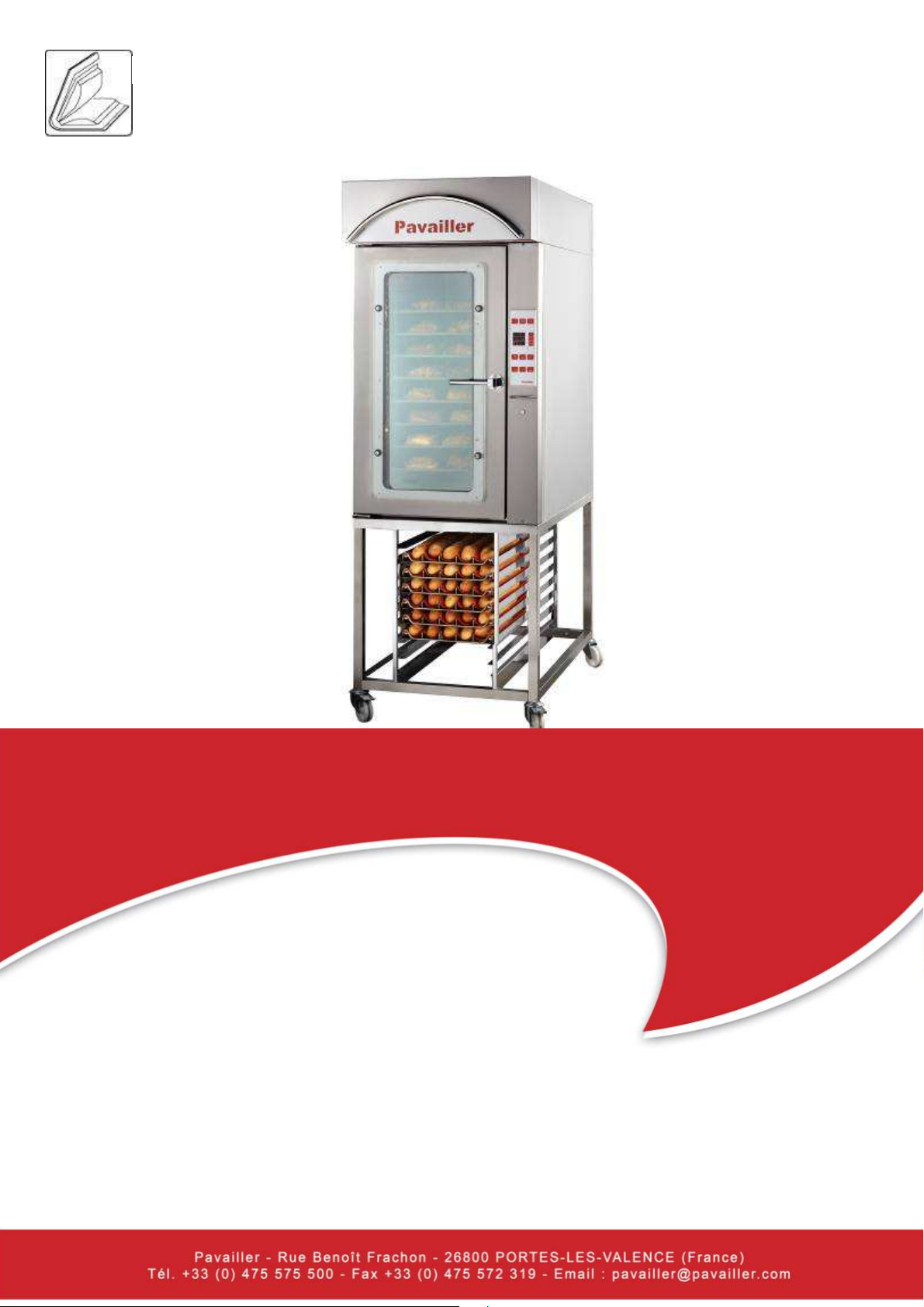
♦ Ovens from the TOPAZE STYLE range are heated electrically and are fitted with a ventilation
system in the baking chamber.
♦ TOPAZE STYLE ovens are available in 4 versions:
L10B model :
Baking racks are 96mm apart.
The model L10B has a capacity of 10 baking pans (400x800 or 460x760).
C10B model :
Baking racks are 96mm apart.
The model C10B has a capacity of 10 baking pans (400x600 or 460x660).
L04B model :
The model L04B has a capacity of 4 or 5 baking pans 400x800 or 460x760.
400x800: Baking racks are 96mm apart. It is possible to add a 5th level with 2 supplied slide
channels. The spacing will be 75 mm.
460x760: Baking racks are 86 mm apart, 69 mm with a 5th level.
C04B model :
The model C04B has a capacity of 4 or 5 baking pans (400x600 or 460x660).
400x800: Baking racks are 96mm apart. It is possible to add a 5th level with 2 supplied slide
channels. The spacing will be 75 mm.
460x660: Baking racks are 86 mm apart, 69 mm with a 5th level.
♦ All TOPAZE STYLE ovens are fitted with steam generators
♦ The baking chamber and exterior panels are made out of 100% stainless steel.
♦ The electronic panel installed on the front houses all the oven controls.
♦ The baking time can be programmed for a period of up to 60 minutes.
♦ An alarm indicates the end of the baking cycle.
♦ TOPAZE STYLE ovens have an interior light in the baking chamber and a reversible door (left
or right opening). The internal door on hinges is easily opening under tool to facilitate the
cleaning (cf. Maintenance page 22).
♦ All TOPAZE ovens are designed for the attachment and connection of a hood.
4
26800 PORTES LES VALENCE – FRANCE
TOPAZE STYLE OVEN Translated manual N°20045080-05
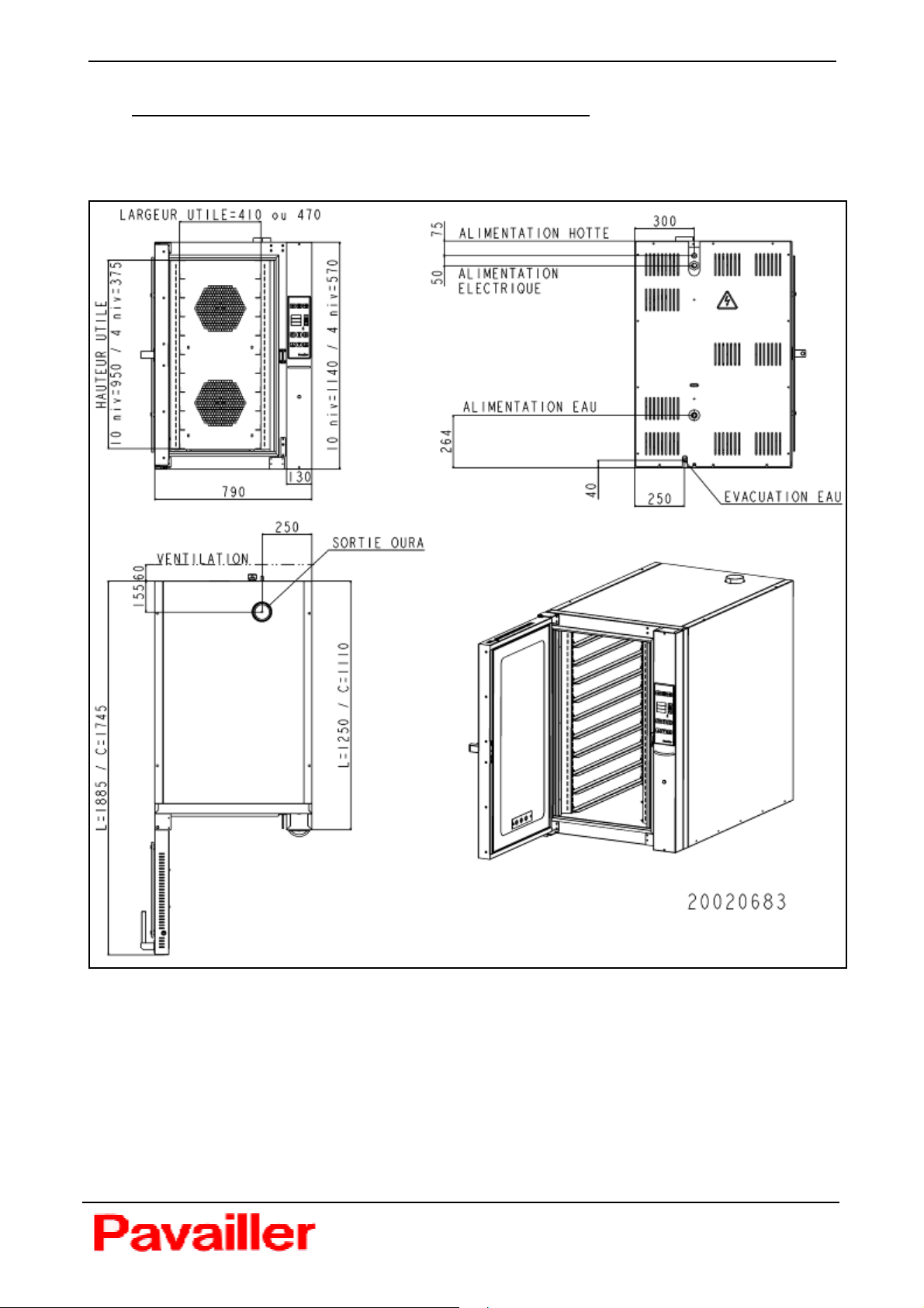
1.2 OVERALL DIMENSIONS OF TOPAZE STYLE OVENS
5
26800 PORTES LES VALENCE – FRANCE
TOPAZE STYLE OVEN Translated manual N°20045080-05
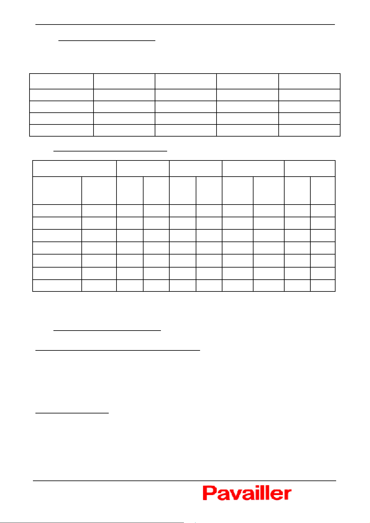
1.3 DIMENSIONS AND WEIGHT
A free space of 60mm is required behind the oven for ventilation of the electrical devices and for
the various connections (cold w ater, evacuation, electricity)
Models L10B C10B L04B C04B
Width (mm) 790 790 790 790
Depth (mm) 1360 1220 1360 1220
Height (mm) 1150 1150 570 570
Weight (Kg) 250 230 155 155
1.4 POWER AND INTENSITY TABLE
Oven type L10B C10B L04B C04B
Voltage
208V 50/60Hz
220V 50/60Hz
230V 50/60Hz
240V 50/60Hz
380V 50/60Hz 3 + N + T 17.1 28.5 17.1 28.5 9.4 14.2 9.4 14.2
400V 50/60Hz 3 + N + T
415V 50/60Hz 3 + N + T 20.5 31.1 20.5 31.1 11.2 15.5 11.2 15.5
Installed electrical power ratings are given w ithout the steam extraction hood.
Add 1A and 180W to obtain the current and power of the oven w ith hood.
No. of
phases
3 + T 16.2 43.4 16.2 43.4 8.4 23.2 8.4 23.2
3 + T 18.1 46 18.1 46 9.4 24.6 9.4 24.6
3 + T 19.8 48 19.8 48 10.3 25.9 10.3 25.9
3 + T 21.6 50 21.6 50 11.2 26.8 11.2 26.8
P
(kW) I (A) P (kW) I (A)
19 30 19 30 10.3 14.9 10.3 14.9
P
(kW)
I
(A)
P
(kW) I (A)
1.5 OPTIONS AND ACCESSORIES
Options for ovens from the TOPAZE STYLE range:
♦ Proofer box or base
♦ Extraction hood or condenser
Topaze oven proofers and bases can be supplied with feet or castors.
The oven’s electromechanical controls can be replaced w ith a programmable electronic interface
Available accessories:
♦ Pans, Trays
6
26800 PORTES LES VALENCE – FRANCE

TOPAZE STYLE OVEN Translated manual N°20045080-05
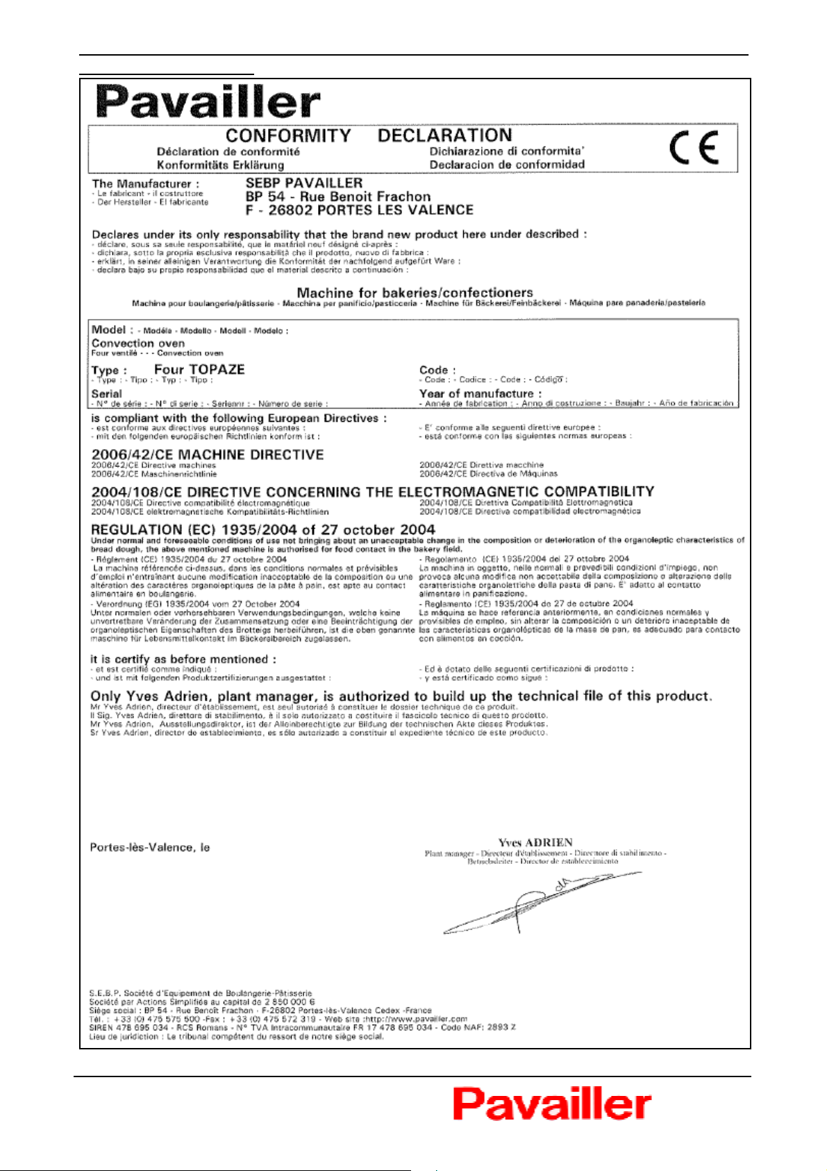
1.6 CONFORMITY OF REGULATIONS
The equipment is in compliance with the follow ing European
directives:
♦ 2006/42/CE Directive machines
♦ 2004/108/CE Directive electromagnetic compatibility
♦ Reglement (CE) 1935/2004 of 27th octobre 2004
This conformity is attested by :
♦ The mark of conformity CE indicated on the descriptive label
fixed behind the oven
♦ The declaration of conformity CE joined with the oven (see
typical declaration page 8)
♦ The present original note of instructions which must be
communicated to the fitter and to the user
1.7 ACOUSTIC CHARACTERISTIC
The level of acoustic pressure measured according to the trial code PREN 454 is lower in 70dBA.
1.8 INSTRUCTIONS OF RECYCLING
In compliance with the current regulations this symbol indicates that the product
may not be disposed of with household w aste at the end of its service life.
To protect the environment the product must be taken to a collection point suitable
for its treatment, valorisation and recycling.
The user thus helps to preserve natural resources and to protect health.
Packaging :
Ovens TOPAZ STYLE are delivered in a packaging to protect it from damage from transport.
Packaging materials are raw materials and are recyclable. If they are not preserved, please recycle
these materials.
For more information concerning the recycling, please contact your local administration which will
inform you on the scene about collection of the waste and the opening hours.
Mechanical parts :
Concerning the environmental protection, the hoarse or worn mechanical parts must be recycled
(iron framew ork).
7
26800 PORTES LES VALENCE – FRANCE
TOPAZE STYLE OVEN Translated manual N°20045080-05
Declaration of conformity
:
8
26800 PORTES LES VALENCE – FRANCE

TOPAZE STYLE OVEN Translated manual N°20045080-05
2 INSTALLATION AND COMMISSIONING
2.1 INSTALLATION
Installation recommendations :
TOPAZE STYLE ovens are delivered ready for use. The required connections can be set up very
easily. How ever, certain precautions must be taken to obtain optimum performance from your
oven.
Please check that :
♦ The passages of door are self-important dimensions to allow to pass the packaging or the oven
with nude (table 1.3 page 6).
♦ Its definitive place of installation can support the mass of the oven (we recommend you the
steam room or the optional available special base on all the ovens)
♦ The ground is plan and of level (Otherw ise prefer a base or a steam room to adjustable feet).
♦ The room is equipped :
• of the power supply adapted to the type of the oven (minimal electric pow er to respect, to
see picture paragraph 1.4 page 6),
• of a system of electric insulation / protection and cut in load calibrated according to the
picture paragraph 1.4 page 6 (switch to be planned by the customer), easily approachable
and placed near immediate of the oven,
• pipes of sufficient supply and evacuation of water (see picture page 10),
• of a fireplace of evacuation of vapors adapted to the oven,
• of a ventilation of the premises adapted to the settled equipments,
• of a minimum lighting of 300 luxes (cf. NF standard 1837).
Instructions of handling and installation :
♦ Installation of the base :
• Take up the support of the oven (base or steam room) with feet,
• Position the support in the place where the oven is going to work and adjust so necessary
flatness,
• Block the support in position
♦ Installation of the oven :
• Unpack the oven on its palette,
• If you have an equipment of lifting, to girth the oven (2 belts minimum), the rise and to
arrange it on the support
• If you have a system of lifting typical "hoist-stacking truck", to raise the oven with its palette
at the level of the support, then make slide the oven on the support,
• Adjust the oven on the support to align the highly-rated, fix the oven on the support by the
back (to defuse the hood defers)
ATTENTION HIGH CENTRE OF GRAVITY: RISK OF FALL OF THE OVEN ONCE INSTALLS
ON ITS SUPPORT
9
26800 PORTES LES VALENCE – FRANCE
TOPAZE STYLE OVEN Translated manual N°20045080-05
Connection procedure of the steam evacuation
TOPAZE STYLE ovens must be connected to a steam exhaust to the outside.
Installation with Pavailler hood :
Installing the Pavailler hood with the instructions supplied with the hood: connect the exhaust vent
on the hood to the oven with the cuff diameter 88 and 90 mm diameter hose to the hood. Sealing
betw een the sleeve and the casting with silicone sealant.
The output of the hood is designed with a flexible diameter 125 (supplied).
Installation without Pavailler hood
Without Pavailler hood, The oven must be installed under a hood allowing to get back vapors of
cooking escaping by the door and by the oura behind the oven.
Install necessarily the cuff diameter 88mm on the oura. Use some putty silicone to make the
waterproofness betw een this cuff and the oura.
Connecting the condensate drain to sewer
A discharge pipe (30mm diameter minimum) is expected by the customer for all TOPAZE STYLE
ovens. The slope should be 1cm/m minimum. The condensate is at the bottom and back of the
oven w ith a copper tube 10-12mm diameter slightly exceeding the oven. Connect also the
condensate of the Pavailler hood
Connecting the water supply :
To connect the steam injection there should be a drinkable water supply.
This supply should include a stop valve near the oven, identified and easily accessible. This valve
must be condemnable by padlocks in closed position. The pressure must be between 1 and 7 bar.
A hose type « Washing machine » in 20-27 femal is supplied with the oven. Plan an arrival in 20-27
male.
Table of electrical connections :
Ovens type L4/C4 L10/C10
Câbles 208 à 240V 4 x 4 mm2 4 x 10 mm2
380 à 415V 5 x 2,5 mm2 5 x 6 mm2
♦ Sections are given for H07RNF w ires to a maximum temperature of 30°C and w ith a maximum
length of 8 meters.
♦ Your disconnecting switch must be sized to the table of intensities above.
♦ PAVAILLER hood or condenser: a terminal block located at the back of the oven is provided for
the electrical supply to the hood (2A maximum). The hood control (switch) is positioned on the
panel on the oven front.
10
26800 PORTES LES VALENCE – FRANCE
TOPAZE STYLE OVEN Translated manual N°20045080-05
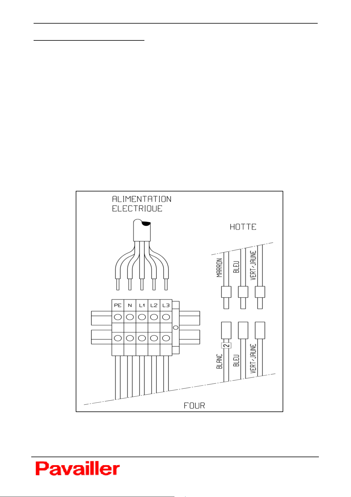
Procedure of electrical connection :
If the oven’s installation site meets the recommendations described above, you can now connect it
by doing the follow ing:
♦ Make sure you have a suitable switch-disconnector.
♦ Install the switch-disconnector and connect the wire. For safety reasons, make sure that the
switch is on the OFF position.
♦ The oven’s power w ire is supplied and installed. It goes beyond the stuffing box at the back of
the oven.
♦ Fix the wire to the switch-disconnector.
♦ Firmly tighten the screws of the terminals, w ires must not move from their slot.
♦ To connect electrically a hood or a condenser PAVAILLER, disassemble the back cover of the
oven and connect wires following the diagram below. Firmly tighten the terminal screws and
remount the rear cover.
PL20020331
11
26800 PORTES LES VALENCE – FRANCE

TOPAZE STYLE OVEN Translated manual N°20045080-05
2.2 START-UP
♦ Make sure that the oven door and the steam evacuation outlet are closed.
Outlet handle fully engaged for the electomechanical model.
Red LED (rep 7 page 15) for the electonic model.
♦ Turn switch-disconnector ON
♦ Set the temperature on the regulator (see page 14) or the electronic plate (see page 19) to the
required value.
♦ Press the ventilation control key :
Using sw itch (3) (see page 14) for the electomechanical model,
Using the ON/OFF key (see page 15) for the electonic model.
Turbine(s) at the bottom of the baking chamber should begin to turm within 20 second.
♦ Your oven is now in preheating mode.
Nota : The rotation of the turbine(s) is reversed at regular time intervals, in order to standardize the
temperature in the cooking chambe.
CAUTION ON THE RISKS OF BURNS :
During all the duration of use of the oven in cooking, from the preheating to the cooling, there are
residual risks of burns, particularly at the front of the oven, especially on articulated windows.
Wearings personal protective equipement like anti-scald gloves is REQUIRED for the introduction
and the withdrawal of cooking support in the oven, and for opening the zipper of fresh air.
If the door is open during cooking or at the end of cooking, it is strongly recommanded to open the
door in 2 steps :
Unlock with the handle and opening up slightly to let off the steam in the oven (which can
cause burning)
Open the door once the steam completely removed
In case of malfunction of the valve steam injection, there are residual risks of scalding on opening
the oven door.
When the door is open, aware of the risk of burns and shear-training on the turbines at the bottom
of the oven; risk of burns by pressing the sensor and door opening button steam injection.
♦ To stop the oven, press the switch control ventilation (3) (see page 14) ou ON/OFF (see page
15).
12
26800 PORTES LES VALENCE – FRANCE
TOPAZE STYLE OVEN Translated manual N°20045080-05
3 UTILISATION ET MODE D'EMPLOI
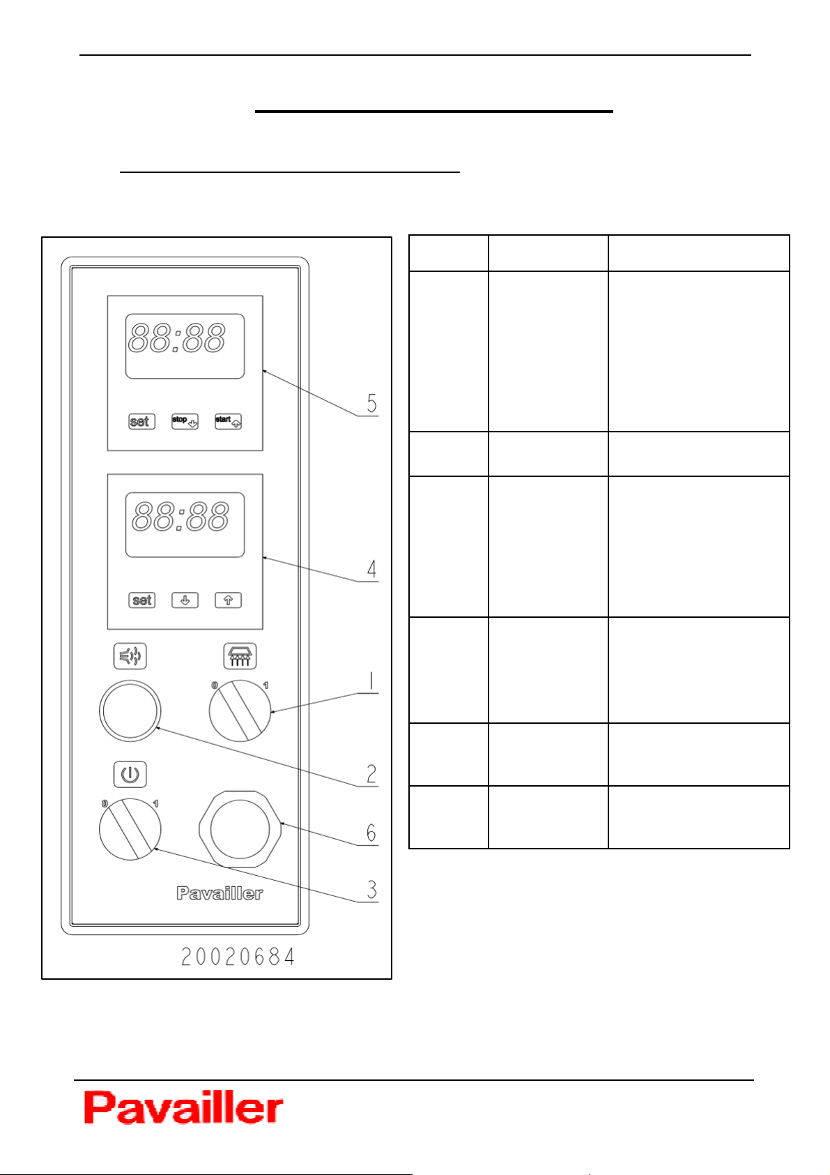
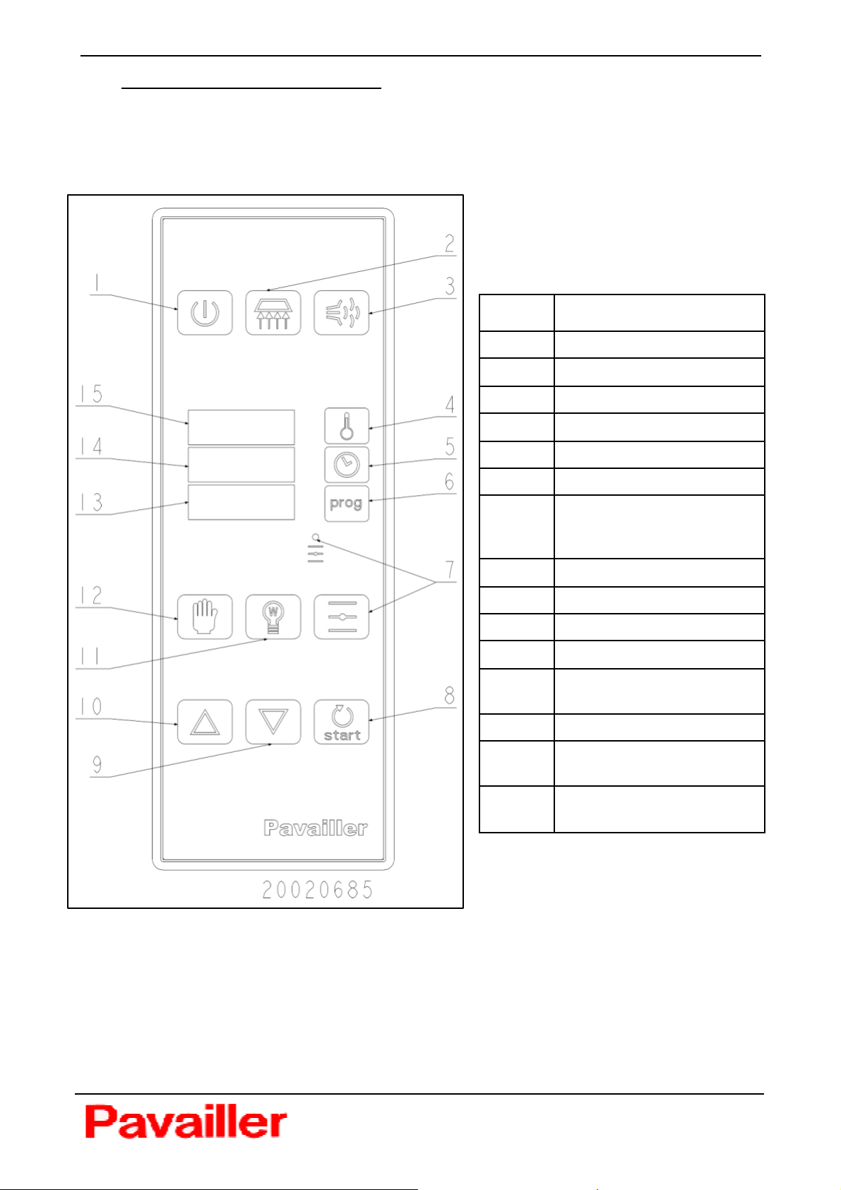
3.1 ELECTROMECHANICAL CONTROL PANEL
3.1.1 Présentation
Ref Description Use
1
2 Steam button
3
Hood Power
Button (or
condenser)
Oven control
button
o Turn the button to
position 1 to start the
hood (or condenser):
Green light goes on.
o Turn the button to
position 0 to stop the
hood extractor (or
condenser).
Allows injection of steam
(6 seconds maximum).
o Turn the button to
position 1 to start oven.
Allows programming
the regulator. Green
light goes on.
4
5 Timer
6 Buzzer alert
Temperature
regulator
o Turn the button to
position 0 to stop oven.
Indicates oven
temperature
Used to display and
adjust temperature
settings.
Display programmed
baking time from 0 to 60
minutes.
Signals end of baking
cycle when timer
reached zero.
13
26800 PORTES LES VALENCE – FRANCE
TOPAZE STYLE OVEN Translated manual N°20045080-05
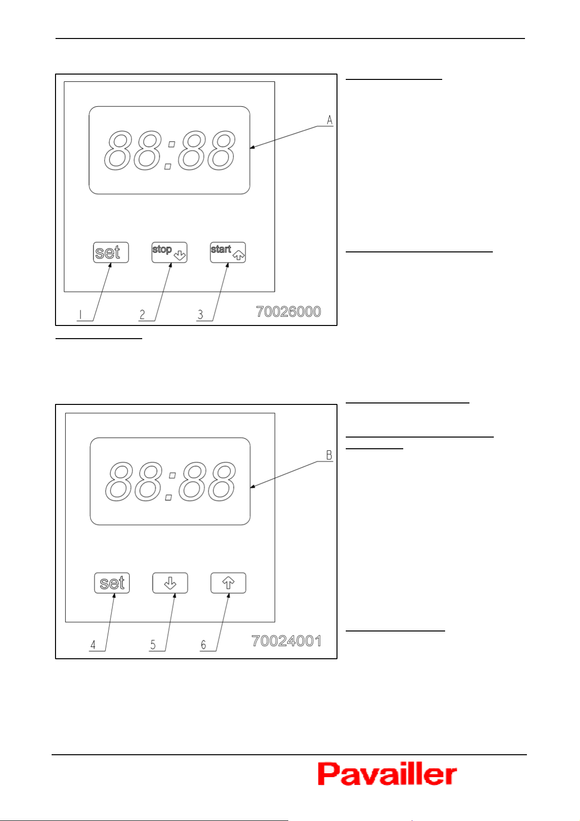
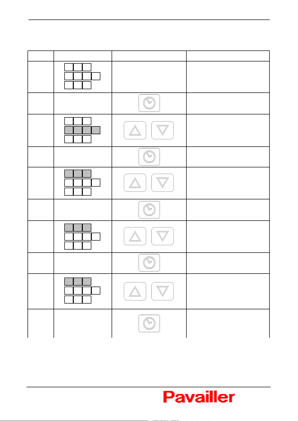
3.1.2 Baking timer
Setting baking time :
Press SET key (1) once to enter
minutes. 2 figures of minutes flash on
and off (A).
Use key (2) and (3) to reduce or
increase time.
Press SET again to enter seconds.
2 figures of seconds flash on and off
(A).
Use key (2) and (3) to reduce or
increase time.
Press SET key or wait 4 seconds to
exit baking time settings.
Baking cycle countdow n timer :
Press START key once (3).
The time in minutes and seconds
begins to count down.
While counting down, the timer can
be stopped by pressing the stop
button.
End of countdow n
When the time 00 :00 is reached, the buzzer sounds (don’t cut the oven).
Press the STOP key to turn off buzzer and return to the programmed baking time.
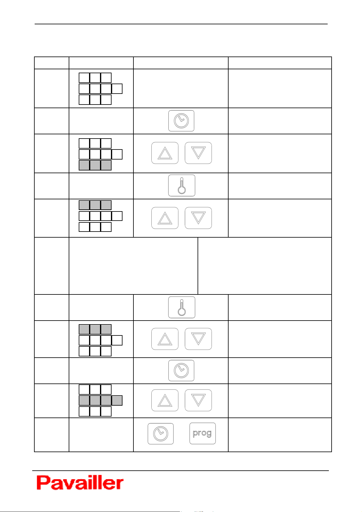
3.1.3 Temperature regulator
Oven temperature reading
Permanently displayed at A.
Reading and adjusting required
temperature
Press SET (4) key once. The
thermometer symbol flashes below
on the left. The device displays the
required temperature.
You can adjust the temperature up
and dow n using the arrow keys (5)
and (6).
To return to the oven’s actual
temprature press the SET key once.
The thermometer symbol goes out.
As soon as the required temperature
is reached the display OUT1 goes
out.
Locking the regulator
Press and hold down the ‘up’ arrow
(6) until the device displays 0-nn.
The regulator is now locked. By
pressing SET, O-nn is displayed and you cannot read or modify the required temperature. To
unlock, press and hold down the ‘up’ arrow until 0-nn disappears (press for about 4 seconds).
14
26800 PORTES LES VALENCE – FRANCE
TOPAZE STYLE OVEN Translated manual N°20045080-05
light
3.2 ELECTRONIC CONTROL PANEL
3.2.1 Présentation
Ref Description
1 Start of oven
2 Stat/Stop the extractor hood
3 Steam injection
4 Temperature settings
5 Timer
6 Choice of the program
7 Oura’s opening and light
(light on = oura is open ;
off = oura is closed)
8 Starting up of the cycle
9 Key set « down »
10 Key set « up »
11 Stat/Stop the oven’s light
12 Access to the "manual"
mode
13 Current program
14 Baking time (or
programming)
15 Baking temperature (or
programming)
15
26800 PORTES LES VALENCE – FRANCE
TOPAZE STYLE OVEN Translated manual N°20045080-05
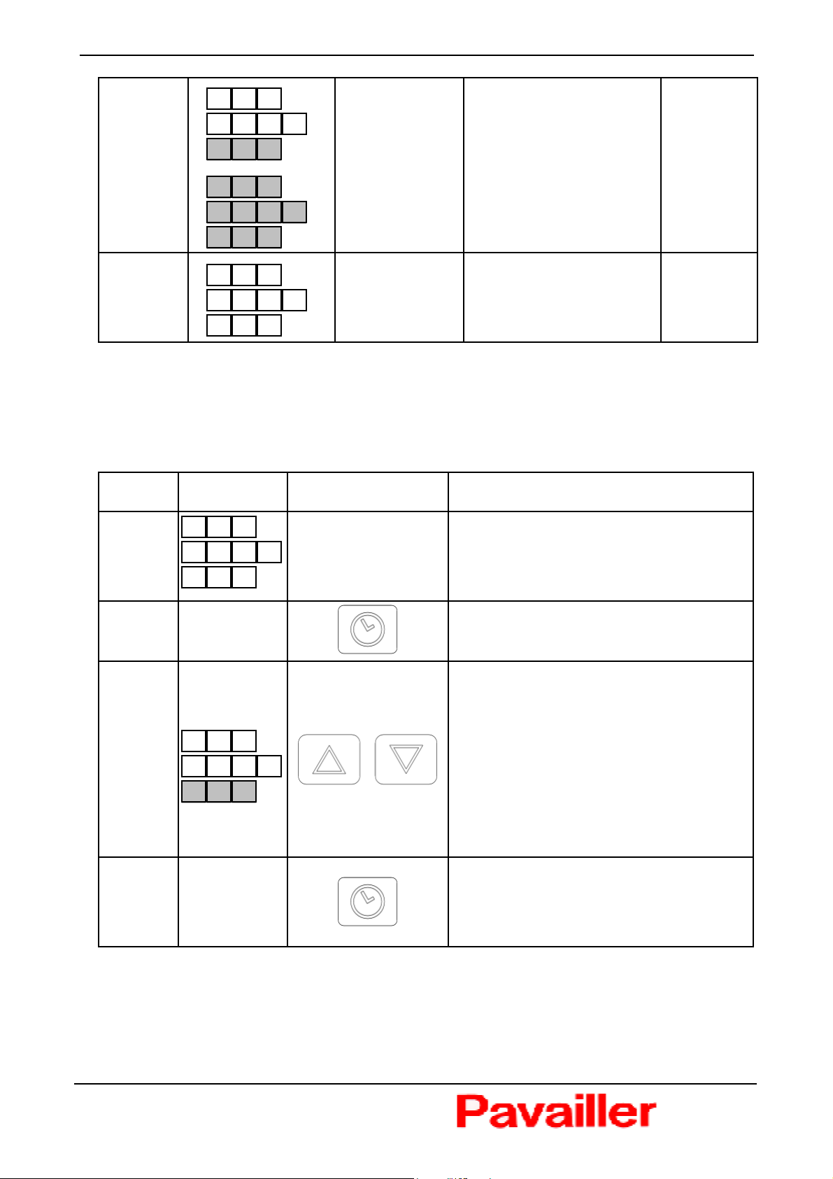
3.2.2 Date setting
STAGES
0
1
2
DISPLAY KEY ACTION
2 5 0
P 0 1
1 2 2 1
9 3 2 0
1 1
- 9 9 0
PREHEATING MODE
Oven temperature : 250°
Hour : 11h22
Program : 01
Press 5 s
HOUR setting
Validation
YEAR setting
3
4
0 4
- 1 2 0
1 2
- 3 1 0
Validation
MONTH setting
Validation
DAY setting
Validation
Press 5 sec or
wait 10 sec
16
26800 PORTES LES VALENCE – FRANCE
TOPAZE STYLE OVEN Translated manual N°20045080-05
H
3.2.3 Deferred starting up (Manual or automatic functioning)
STAGES
0
1
2
DISPLAY KEY ACTION
- 1 8 2 0 1
SLEEP MODE
Day : Monday
Hour : 18H20
- - -
- - - -
0 1
Clock Selection
- 2 -
H 0 1
Day Selection
Press 5 s
Validation
3
4
1 = Monday
2 = Tuesday
3 = Wednesday
4 = Thursday
5 = Friday
6 = Saturday
7 = Sunday
P 0 1
H 0 1
- 2 6 0 0 0
H 0 1
1-5 = Monday to Friday
1-6 = Monday to Saturday
1-7 = Monday to Sunday
6-7 = Saturday to Sunday
Validation
Program Selection
Validation
Hour Selection
OR
Deferred starting up
validation : Press 5 s
17
26800 PORTES LES VALENCE – FRANCE
TOPAZE STYLE OVEN Translated manual N°20045080-05
}
-
C
Display
Deferred
mode
If clock
ON
- 1 -
- 2 -
H 0 1
8 2 0 1
- -
6 0 0 0
Current state
(Day and hour)
Programming
(Day, hour and
program)
In
Alternation
If clock
OFF
In the stop of the oven, the next starting up is looked for according to day and the hour of the
programmed clocks. It is possible to program a maximum of 14 clocks.
3.2.4 Meter of functioning
STAGES DISPLAY KEY ACTION
0
- 1 -
- 1 8 2 0 1
8 2 0 1
Sleep
mode
SLEEP MODE
Day : Monday
Hour : 18H20
1
2
2 7 H 1
0 1
Meter selection :
C01 = Nb hours of functioning of the
card (switched on)
C02 = Nb hours of use
C03 = Nb hours with stoking
C04= Nb hours without stoking
C05 = Nb started cycles (button 8)
C06 = Nb steam cycles (button 3)
Exit of display
Press 5 sec or
wait 10 sec
18
26800 PORTES LES VALENCE – FRANCE
 Loading...