

Page 1
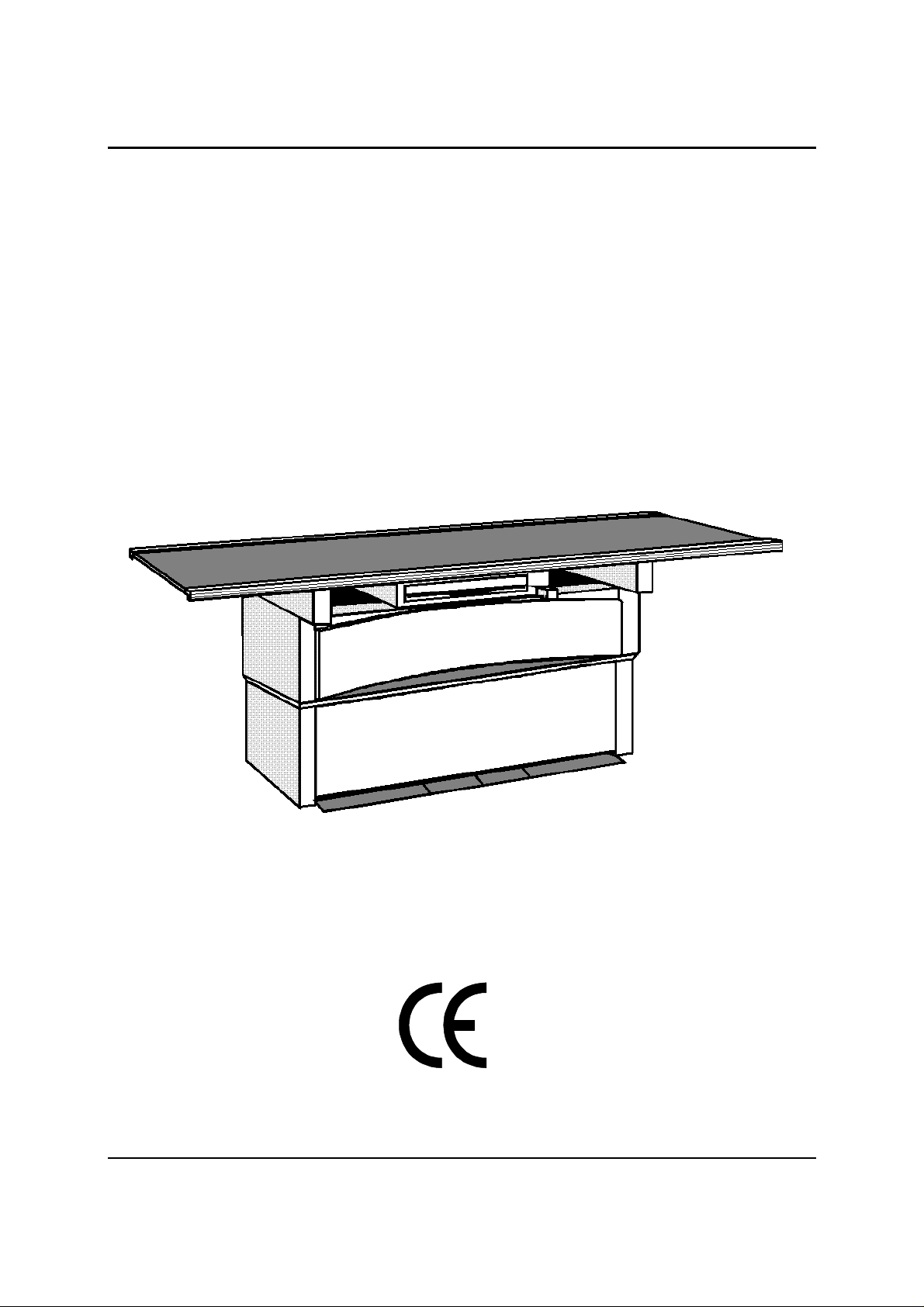
Mounting Instructions ELEVATOR-2
0125
English Edition
07/98 1 von 34 0627 7226
Rev. 02 © 1998 Hans Pausch Röntgengerätebau Graf-Zeppelin-Str. 1 D-91056 Erlangen ALL RIGHTS RESERVED Ru
Page 2

TABLE OF CONTENTS Page
1. Specification
1.1 General safety notes 3
1.2 Compatibility 3
1.3 Environmental conditions 3
1.4 Dimensions and weights 3
1.5 Component Designation 4
1.6 Dimensional Drawing 5
1.7 Dimensional Drawing/Floor Mounting 6
1.8 Cable routing 7
1.9 Constructional preparations 7
1.10 Measuring tool required 7
1.11 Special tools required 7
1.12 Mains data 7
1.13 Schematics 8
1.14 Component Numbers and Designation 12
2. Mounting of Unit
2.1 Floor preparation 14
2.2 Unpacking and Preparing the Table 14
2.3 Table Installation and Leveling 15
2.4 Bucky Installation 16
2.5 Mounting of Table Top 17
2.5.1 Mounting of Table Top in Small Rooms 18
2.6 Functional checking 19
2.7 Mounting of Trim covers 19
3. Adjustments
3.1 Exposure Height Adjustments 19
3.2 Adjustments of Electronics 19
3.3 Adjustments of Bucky in transverse direction 20
4.0 Technical Maintenance
4.1 Mechanical and electrical Checks 21
4.2 Functional Checking 26
4.3 Spare Parts Table 27
4.4 Spare Parts List 29
4.5 Name plate location 32
4.6 Maintenance Documentation 33
0627 7226 2 von 34 07/98
Rev. 02 © 1998 Hans Pausch Röntgengerätebau Graf-Zeppelin-Str. 1 D-91056 Erlangen ALL RIGHTS RESERVED Ru
Page 3

1. Technical data
1.1 General safety notes
In the Federal Republic of Germany, the electrical installation of rooms for medical
purposes must conform to the provisions VDE Standard 0107. In all other countries
the national requirements have to be observed.
Check the installation layout plan.
During the installation it is important to check that all protective ground wire
connections provided by the manufacturer are properly made before the equipment is
switched on.
The protective ground wires between the individual system components and the
power supply have to be connected as shown in the wiring diagram.
Regulation of professional associations concerning safety and accident prevention
must be observed. No work may be performed on parts carrying a voltage higher than
42 V (peak voltage). If it is necessary to turn on the power for execution of
movements of the equipment in the course of installation procedure, it must be shut
down immediately after completion of these movements.
1.2 Compatibility
This mounting instruction is valid for ELEVATOR-2 and all versions of them.
Bucky units made by various manufacturers can be used.
A Bucky Wall stand can be installed either on the right or left hand side of the table.
1.3 Environment conditions
for operation
Ambient Temperature: 10° C to 40° C
Relative Humidity: 20% to 80%
Atmospheric pressure: 700 hPA to 1100 hPa
Sipping conditions:
Ambient Temperature: -25° C to 70° C
Relative Humidity: 5% to 95%
Atmospheric pressure: 600 hPA to 100 h PA
1.4 Dimensions and weights
Components Dimensions of components Weight of components
Table 1400x770x540 mm 215 kg
Table top $ 2200x810x 40 mm 35 kg
Dimensions of boxes Weight of boxes
Table 1530x860x810 mm 260 kg
Table top 2320x930x200 mm 56 kg
07/98 3 von 34 0627 7226
Rev. 02 © 1998 Hans Pausch Röntgengerätebau Graf-Zeppelin-Str. 1 D-91056 Erlangen ALL RIGHTS RESERVED Ru
Page 4
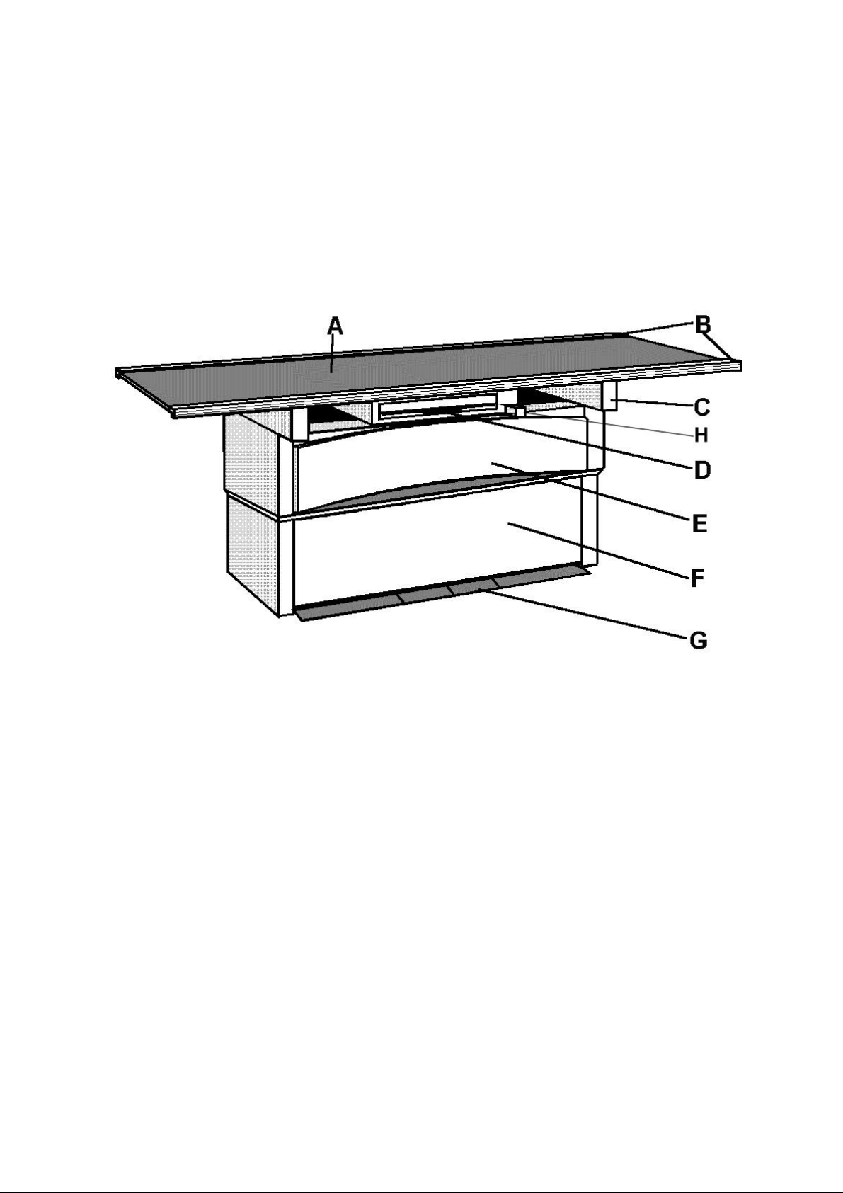
1.5 Component Designation
A Table top, floating, manually movable
B Profile rail, smooth, accepts accessories
C Table frame
D Bucky unit, movable
E Telescopic part of table base
F Table base
G Foot treadle
H Safety switch
0627 7226 4 von 34 07/98
Rev. 02 © 1998 Hans Pausch Röntgengerätebau Graf-Zeppelin-Str. 1 D-91056 Erlangen ALL RIGHTS RESERVED Ru
Page 5
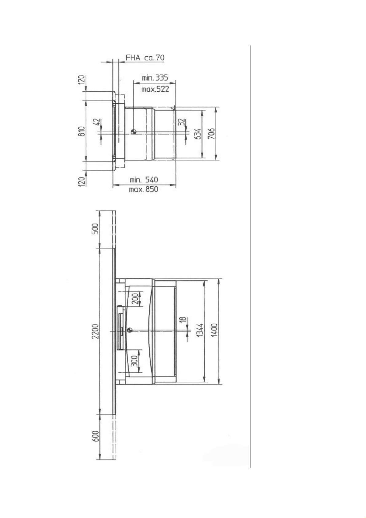
1.6 Dimensional Drawing
07/98 5 von 34 0627 7226
Rev. 02 © 1998 Hans Pausch Röntgengerätebau Graf-Zeppelin-Str. 1 D-91056 Erlangen ALL RIGHTS RESERVED Ru
Page 6
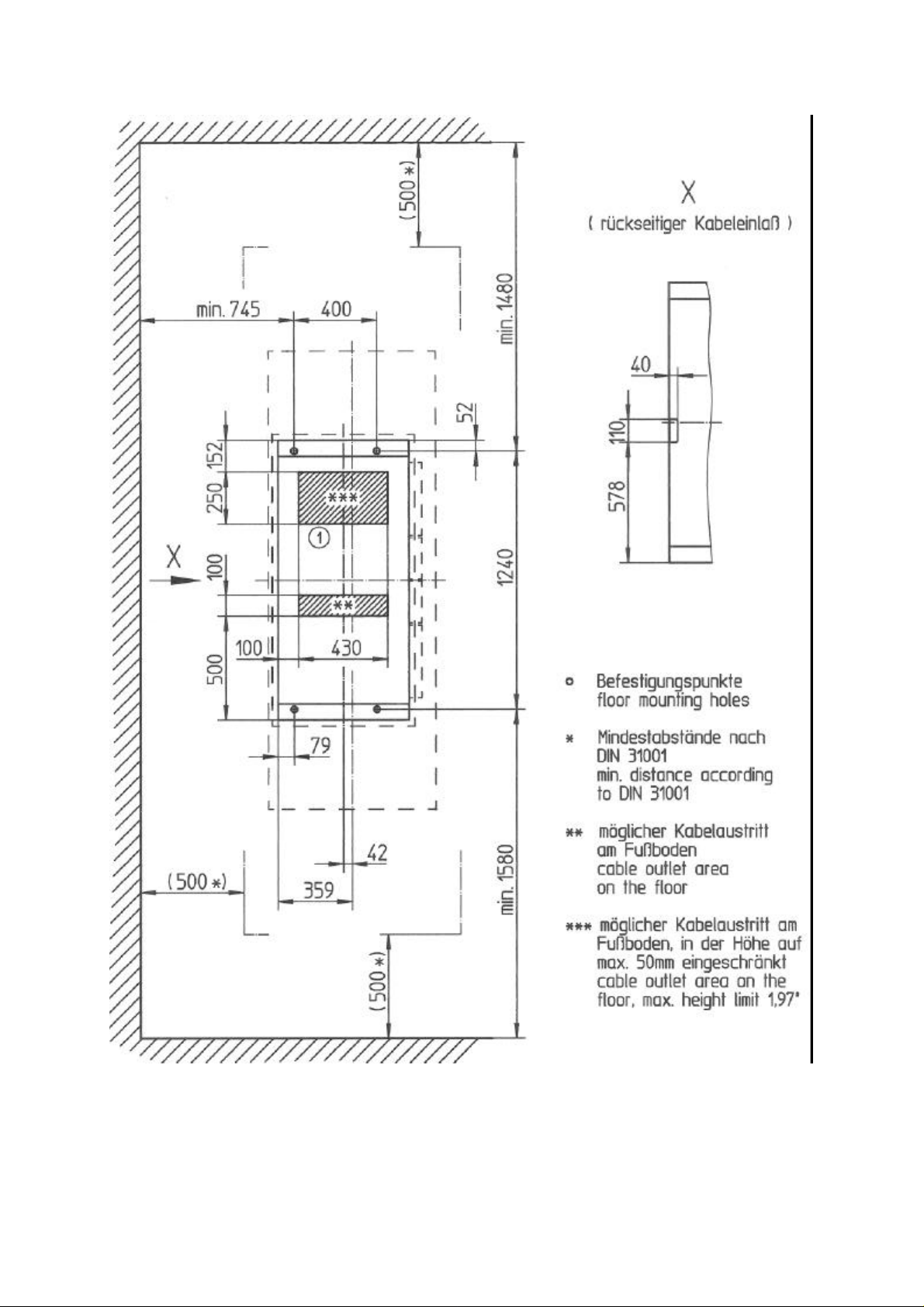
1.7 Dimensional Drawing / Floor Mounting
0627 7226 6 von 34 07/98
Rev. 02 © 1998 Hans Pausch Röntgengerätebau Graf-Zeppelin-Str. 1 D-91056 Erlangen ALL RIGHTS RESERVED Ru
Page 7
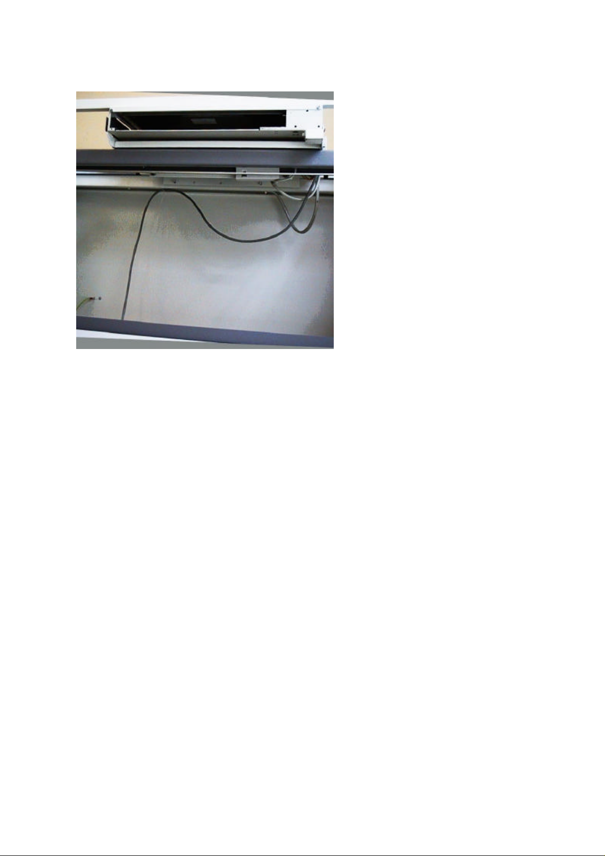
1.8 Cable routing
1.9 Constructional preparations
The electrical connections must comply with the equipment supply voltage.
For the ELEVATOR-2 only a supply voltage of 115/230 V is required and a suitable
ground connection . The fastening points of the ELEVATOR-2 must support a tensile
stress of 2500 N at each mounting point . E.G Liebig safety anchors S12/65 for B 150
DIN 1045 concrete floor ( included fastening material).
Prepare the floor mounting holes with a 12 mm/.472 in. drill according dimensional
drawing 1.7.
The power cable of the ELEVATOR-2, the cable for the Bucky and the Ion chamber
must be routed depending on the version to the interface box in the table base or all
the way to the Bucky according to the installation plan.
1.10 Measuring tool required
Machinist water level
1.11 Special tools required
Rotary hammer
Masonry drill 12 mm
1.12 Power supply data
Power supply: 115/230 V
Frequency: 50 / 60 Hz
Rated current: 10 / 6 A
Rated power supply voltage: 0,7 VA
07/98 7 von 34 0627 7226
Rev. 02 © 1998 Hans Pausch Röntgengerätebau Graf-Zeppelin-Str. 1 D-91056 Erlangen ALL RIGHTS RESERVED Ru
Page 8
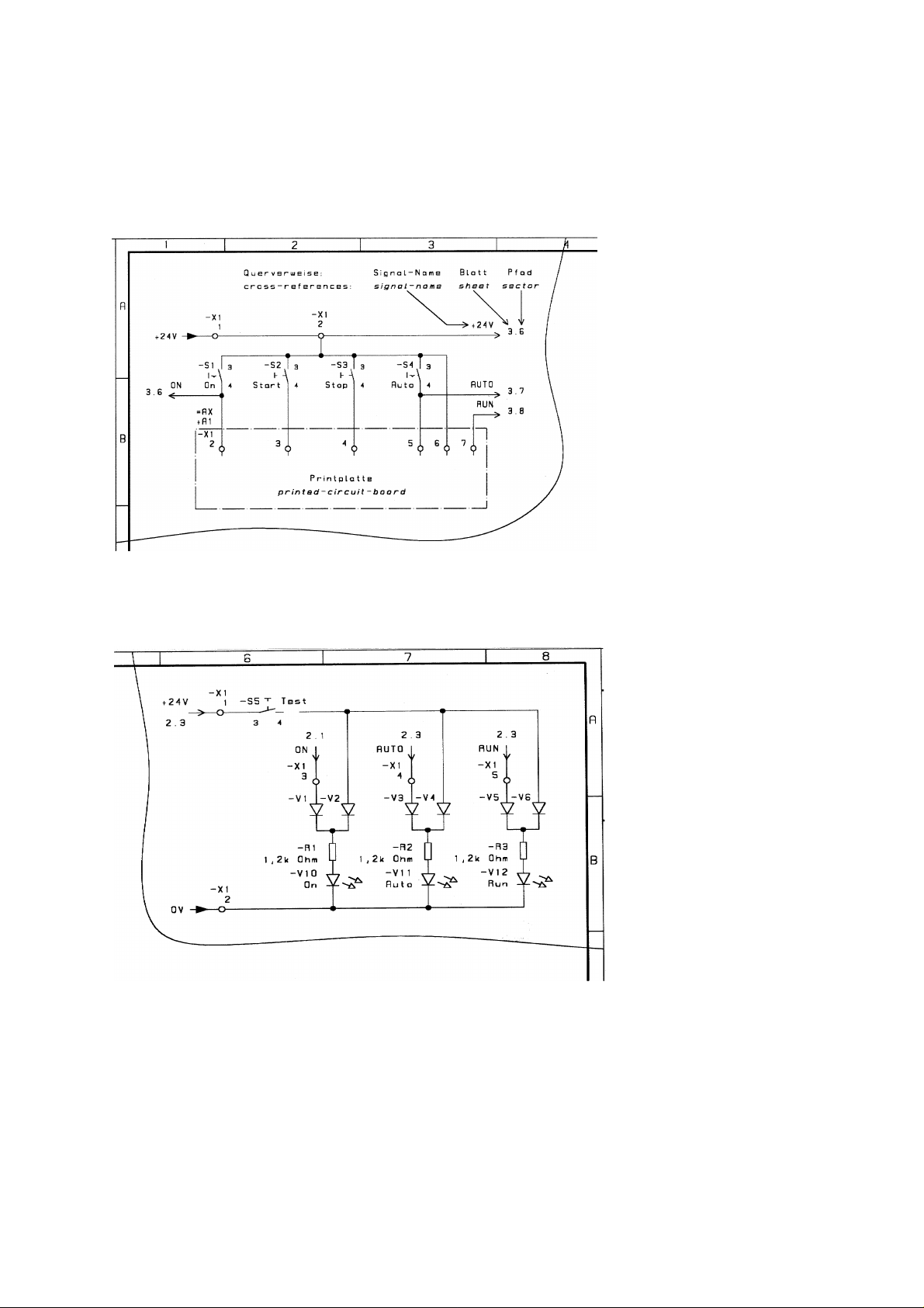
1.13 Schematics sheet 1
1.13.1 Description at Schematics
....... Schematics sheet 2
= AX control panel
= Unit, Indication
...... Schematics sheet 3
= AX control panel
= Unit, Indication
1.13.1 Table of contents at Schematics
Sheet 2 Schematics Main transformer =AF
Sheet 3 Schematics =AF
Sheet 4 Wiring diagram =AF
0627 7226 8 von 34 07/98
Rev. 02 © 1998 Hans Pausch Röntgengerätebau Graf-Zeppelin-Str. 1 D-91056 Erlangen ALL RIGHTS RESERVED Ru
Page 9
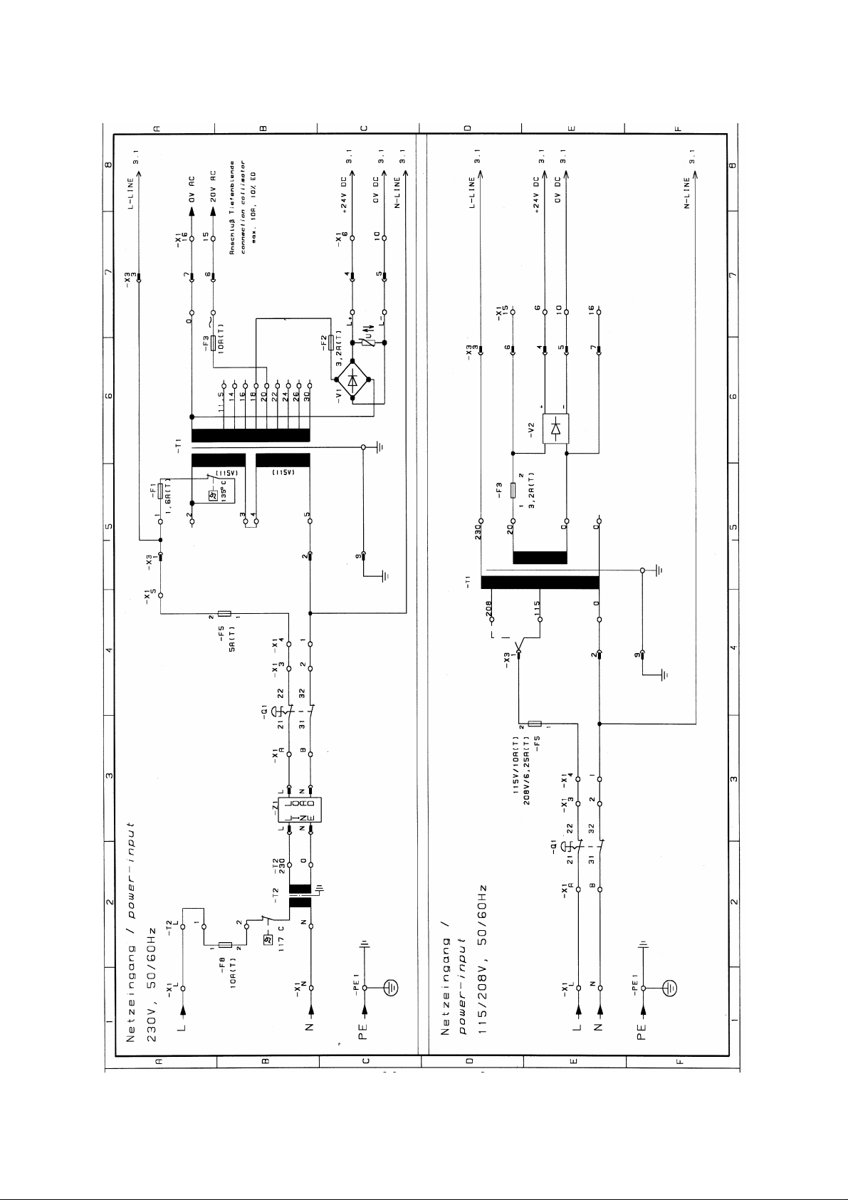
1.13 Transformer Diagram Sheet 2
07/98 9 von 34 0627 7226
Rev. 02 © 1998 Hans Pausch Röntgengerätebau Graf-Zeppelin-Str. 1 D-91056 Erlangen ALL RIGHTS RESERVED Ru
Page 10
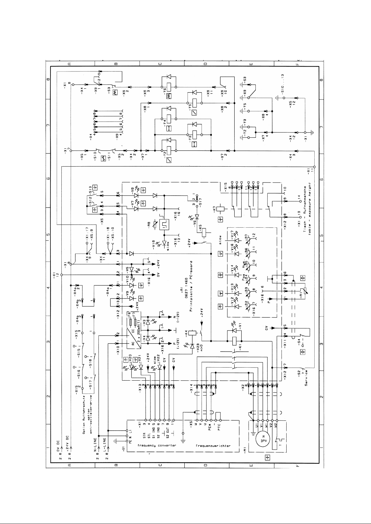
1.13 Schematics sheet 3
0627 7226 10 von 34 07/98
Rev. 02 © 1998 Hans Pausch Röntgengerätebau Graf-Zeppelin-Str. 1 D-91056 Erlangen ALL RIGHTS RESERVED Ru
Page 11
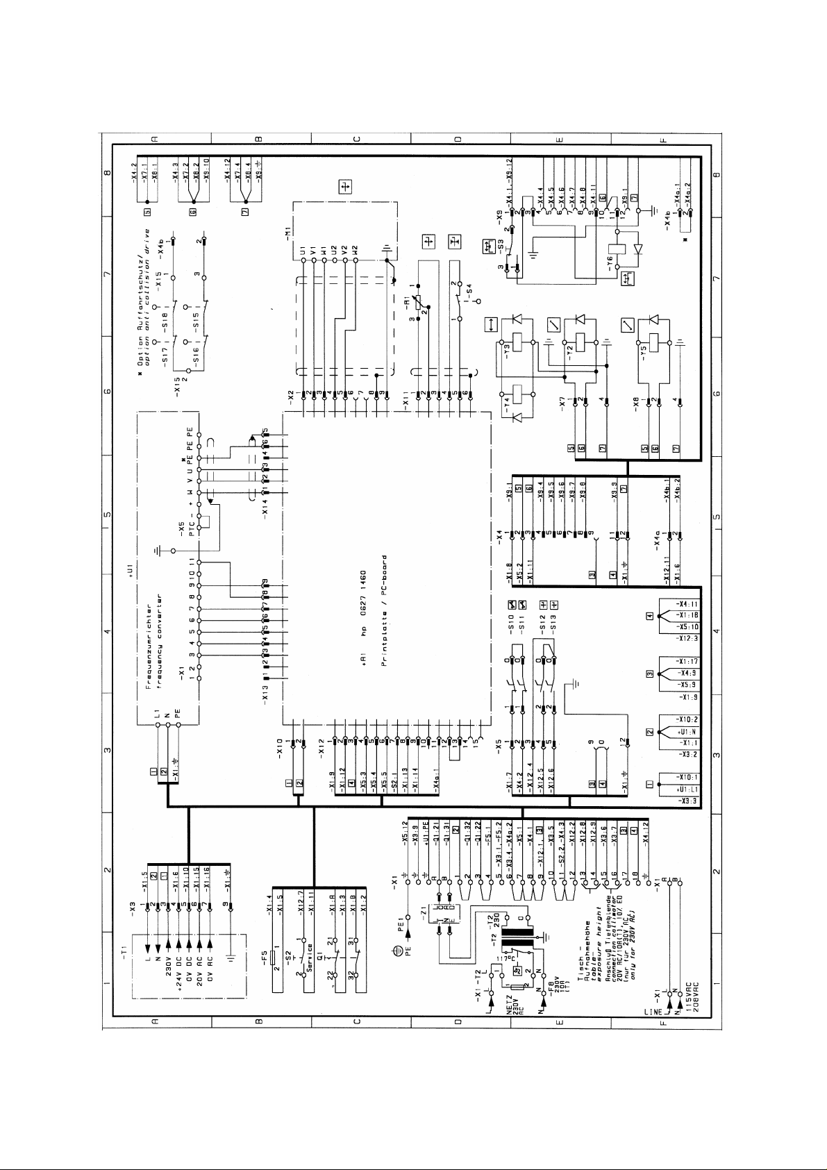
1.13 Wiring Diagram Sheet 4
07/98 11 von 34 0627 7226
Rev. 02 © 1998 Hans Pausch Röntgengerätebau Graf-Zeppelin-Str. 1 D-91056 Erlangen ALL RIGHTS RESERVED Ru
Page 12

1.14 Components Numbers and Designation
No. Designation
=AF+A1 PC Board
+U1 Frequency Converter
-F1 Fuse transformer primary
-F2 Fuse 24 V
-F3 Fuse 20 V AC
-F4 Fuse 130 V
-F5 Fuse mains supply
+A1-F6 Fuse +12 V DC
+A1-F7 Fuse -12 V DC
-F8 Fuse isolating transformer
+A1-K1 Motor conductor
+A1-K2 Relay motor contactor
+A1-K4 Relay n>0
+A1-K5 Relay safety switch
+A1-K6 Relay intermediate stop
+A1-K7 Relay exposure height
-M1 Vertical drive motor
-PE1 Main ground terminal
-Q1 Service switch
-R1 Height potentiometer
+A1-R2 Adjusting screw disconnect vertical top position
+A1-R3 Adjusting screw intermediate stop
+A1-R4 Adjusting screw exposure position
+A1-R5 Adjusting screw exposure position hysterese
+A1-R6 Adjusting screw disconnect lower table position
+A1-R7 Adjusting screw slow motion range
+A1-R8 Adjusting screw slow motion time
-S2 Service - switch
-S3 Switch Bucky brake
-S4 Safety limit switch
-S5 Safety push button
-S10 Foot pedal switch for table top brake
-S11 Foot pedal switch for Table top brake
-S12 Foot pedal switch for vertical upwards
-S13 Foot pedal switch for vertical downwards
-S15 Switch for anti collision drive
-S16 Switch for anti collision drive
-S17 Switch for anti collision drive
-S18 Switch for anti collision drive
-T1 Mainstransformer
-T2 Transformer for electronics
+A1-V1 LED motor contactor
+A1-V3 LED -12 V DC
+A1-V4 LED +12 V DC
+A1-V5 LED +24 V DC
+A1-V6 LED safety switch
0627 7226 12 von 34 07/98
Rev. 02 © 1998 Hans Pausch Röntgengerätebau Graf-Zeppelin-Str. 1 D-91056 Erlangen ALL RIGHTS RESERVED Ru
Page 13

+A1-V7 LED Foot pedal switch vertical up
+A1-V8 LED Foot pedal switch vertical down
+A1-V9 LED limit switch vertical up
+A1-V10 LED limit switch vertical down
+A1-V12 LED disconnect vertical top
+A1-V13 LED intermediate stop
+A1-V14 LED exposure height
+A1-V16 LED disconnect vertical upwards
+A1-V17 LED slow motion range
+A1-V18 LED slow motion time
+A1-V20 LED frequency converter vertical upwards
+A1-V21 LED frequency converter vertical downwards
+A1-V22 LED frequency converter slow motion
+A1-V23 LED frequency converter n>o
-X1 Terminal strip
+A1-X2 Motor plug
-X3 Transformer plug
-X4 Motor drive plug
-X4a Plug anti collision drive
-X4b Plug anti collision drive
-X5 Plug Foot pedal switch
-X7 Plug left lateral brake
-X8 Plug right lateral brake
-X9 Plug Bucky carriage
+A1-X10 Plug mains input
+A1-X11 Plug height measuring unit
+A1-X12 Plug for control signal
+A1-X13 Plug for U1 control signal
+A1-X14 Plug for U1 motor voltage
-X15 Plug for Combi-Elevator
+A1-X15 terminal block for anti collision drive
+A1-X16 Test socket
+A1-X16:1 Check point ground
+A1-X16:2 Check point +12 V DC
+A1-X16:3 Check point -12 V DC
+A1-X16:4 Check point 0 V DC
+A1-X16:5 Check point +24 V DC
+A1-X16:6 Check point actual value height measuring-R1
+A1-X16:7 Check point nominal value disconnection top
+A1-X16:8 Check point nominal value intermediate stop
+A1-X16:9 Check point nominal value exposure Item stop
+A1-X16:10 Check point nominal value exposure Item hyst.
+A1-X16:11 Check point nominal value disconnection bot.
+A1-X16:12 Check point nominal value slow motion range
+A1-X16:13 Check point time impulse exposure
+A1-X16:14 Check point memory signal exposure position
+A1-X16:15 Check point time impulse exposure position
+A1-X16:16 Check point Foot pedal switch vertical up- or downwards
-Y2 Brake table top lateral left
-Y3 Brake table top longitudinal
-Y4 Brake table top longitudinal
-Y5 Brake table top lateral right
-Z1 Filter
07/98 13 von 34 0627 7226
Rev. 02 ©1998 Hans Pausch Röntgengerätebau Graf-Zeppelin-Str. 1 D-91056 Erlangen ALL RIGHTS RESERVED Ru
Page 14
2. Mounting
2.1 Preparing the Floor
Drill holes for the floor mounting of the equipment as shown in dimensional drawing,
page 6, with a 12 mm/.472 in. drill. To ensure full range movability of the system
components, keep the minimum distances indicated. The bolts must be suitable for 2500 N
tensile stress at each mounting point. E.G. Liebig security anchors S12/65 N for DIN
1045 concrete floor.
Remove the vinyl or carpet floor covering around the mounting points for the base of the
unit. Lay floor covering shims (installation material, included with the shipment) of the
same thickness as the original floor covering at the mounting points.
2.2 Uncrating and Preparing the Table
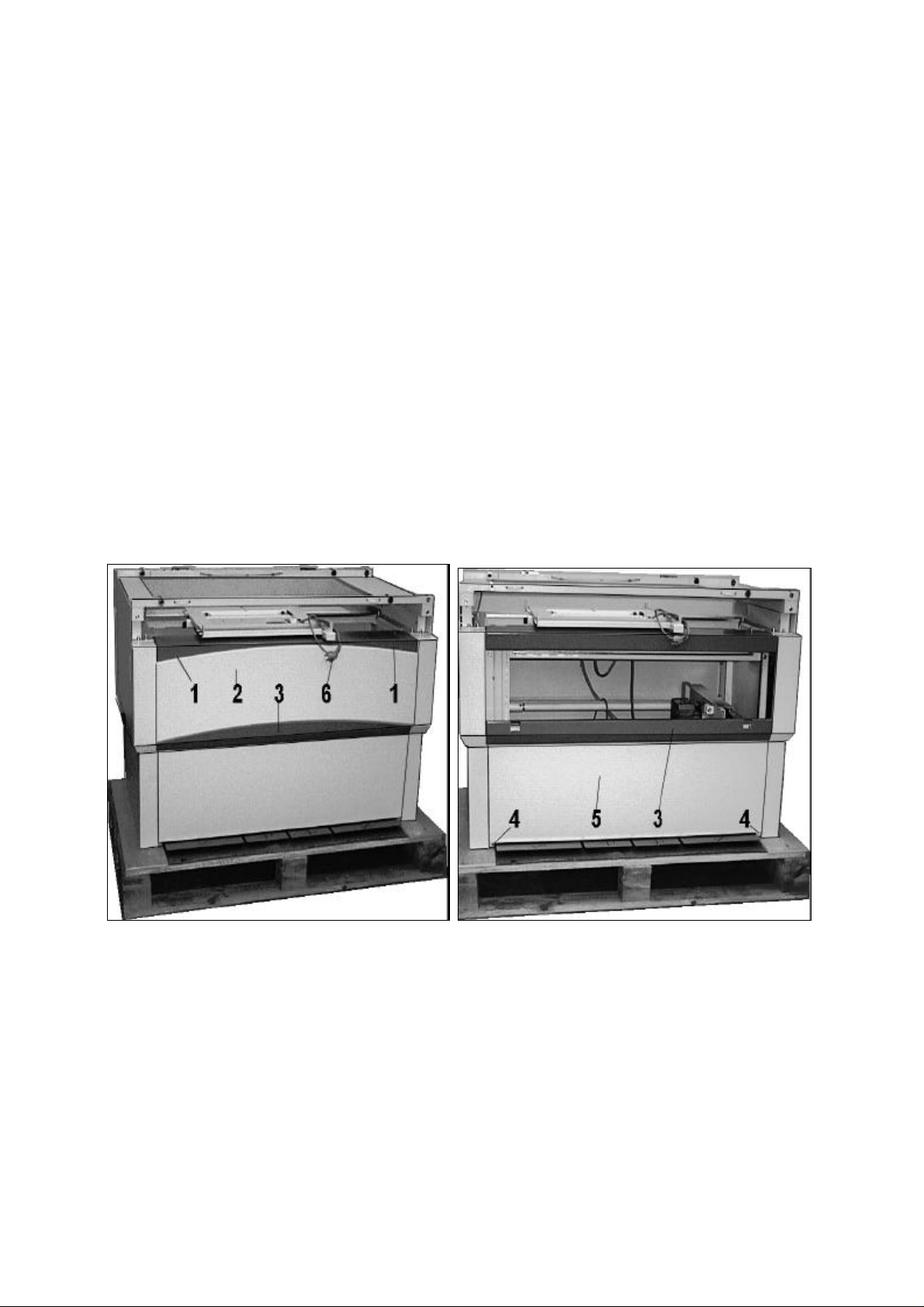
Remove packing material. Make a provisional power connection with the mains cord
(Fig. 1,Item 6) and drive the table to maximum height. Take off plastic caps (Fig.1, Item
1). Loosen socket cap screws underneath with a 4 mm Socket wrench. Swivel the top
cover (Item 2) forward and lift off by pulling upward.
Fig. 1 Fig. 2
Remove both Socket screws and connecting bar (Item 3). Loosen Socket screw (Fig.
2Item 4). Swivel the cover (Item 5) at the bottom forward and pull out downward.
0627 7226 14 von 34 07/98
Rev. 02 © 1998 Hans Pausch Röntgengerätebau Graf-Zeppelin-Str. 1 D-91056 Erlangen ALL RIGHTS RESERVED Ru
Page 15
.
Fig. 3 Fig. 4
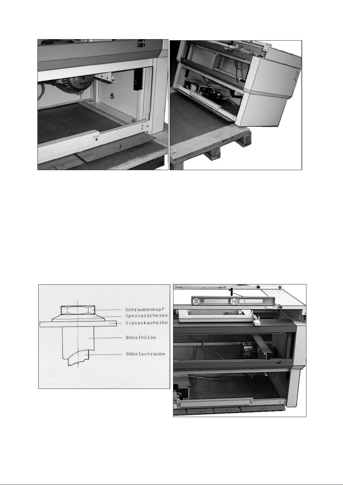
Remove shipping screws (Fig.3, Item 5) from the pallet by pushing them to the floor. Slide
the table to the back of the pallet (Fig. 4). Tilt table to the back and pull out the pallet
underneath. Place Table carefully on the floor.
2.3 Table Installation and Leveling
Lift the table over the prepared floor mounting holes. Prepare heavy-duty anchors as
illustrated (Fig.5). Pass anchor sleeves and bolts through table base mounting holes.
Fig. 5
Fig. 6
07/98 15 von 34 0627 7226
Rev. 02 ©1998 Hans Pausch Röntgengerätebau Graf-Zeppelin-Str. 1 D-91056 Erlangen ALL RIGHTS RESERVED Ru
Page 16
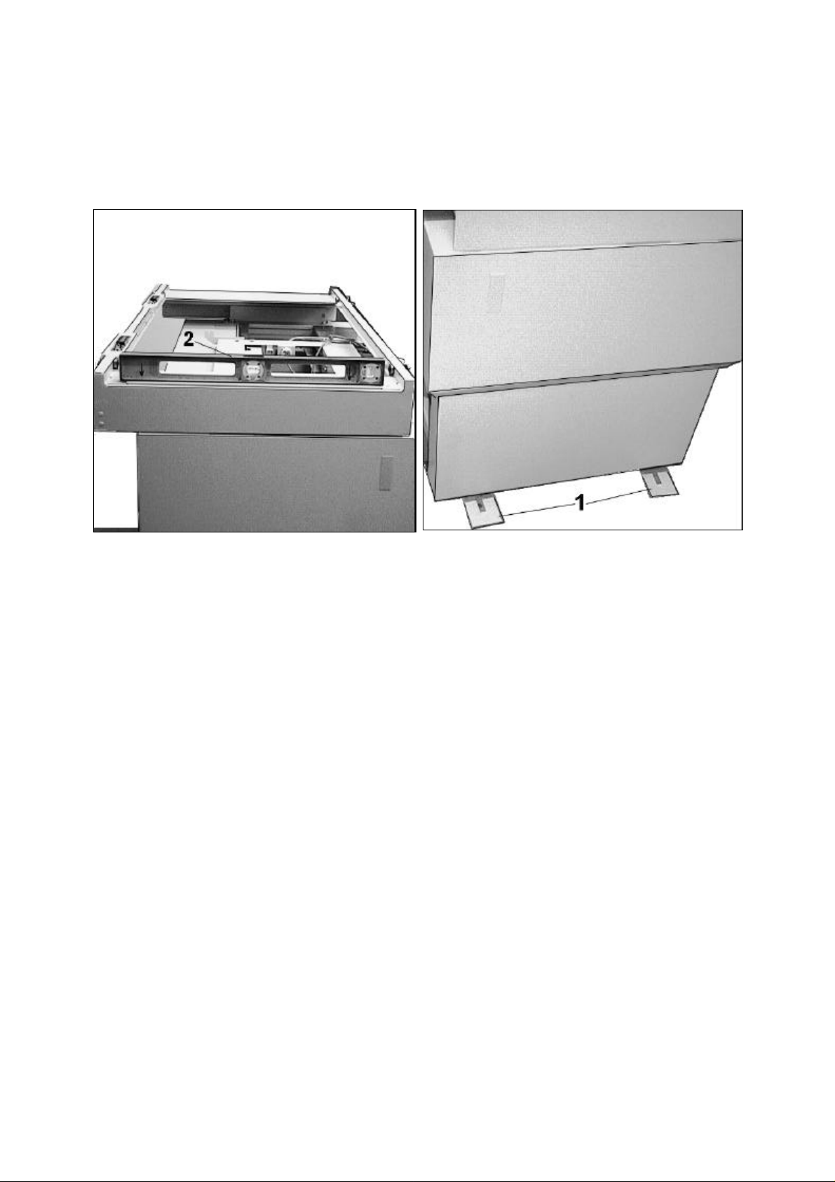
Check table base with water level (Fig.6, Item 1and Fig.7, Item 2) and compensate with
shims, if necessary (Fig. 8, item 1, included with the shipment). Tighten mounting bolts.
CAUTION:
Be careful not to distort the table base in any direction.
Fig. 7 Fig. 8
2.4 Bucky Installation
NOTE:
Buckys of all leading manufacturers can be installed. The unit has been prepared
according to the order. The installation material required is included with the shipment.
Insert the Bucky into the Bucky carriage (Fig. 9, Item 7). The cassette opening must face
front, i.e. direction of the operator. Connect the Bucky cable and the Ion chamber cable
according to the instructions of the Bucky manufacturer.
Bucky Unit P
Fasten with 2 screws each (Fig.9,Item 3) at right- and left-hand side of Bucky. Mount
trim covers as shown in Fig 9, item 4 with 3 screws and washers.
Philips:
Fasten with 2 screws each and washers (Fig.9, Item 3) at the right- and left hand side.
Place trim covers on edges wallside andoperator side (Fig.9, Item 4) and fasten from
above with 3 screws each.
Siemens:
Fasten with 4 screws and washers (Fig.9, Item 3) at right- and left hand side .
0627 7226 16 von 34 07/98
Rev. 02 © 1998 Hans Pausch Röntgengerätebau Graf-Zeppelin-Str. 1 D-91056 Erlangen ALL RIGHTS RESERVED Ru
Page 17
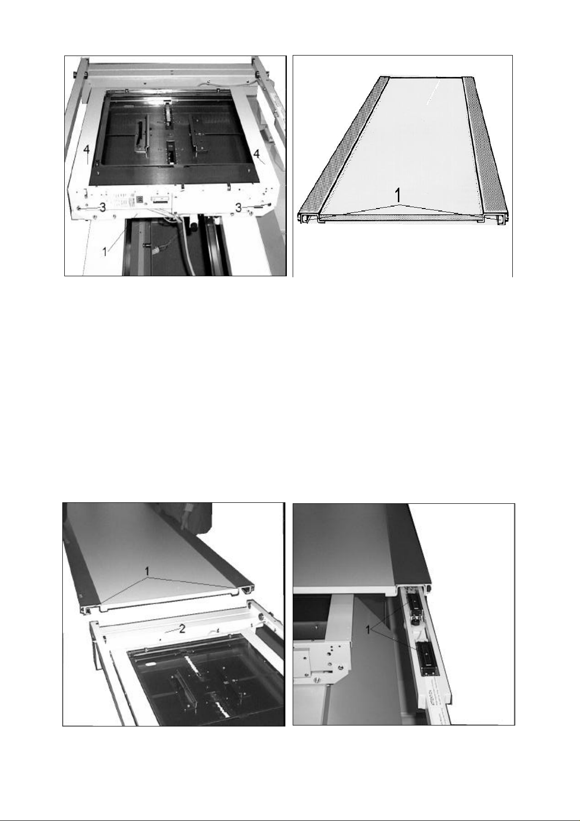
Fig. 9 Fig. 10
2.5 Mounting of Table Top
Note: If there are less than 2900 mm from the middle of table to a wall available, please
mount the table top according section 2.5.1 .
Unpack table top.
Unscrew bumper stops (Fig.10, Item 1) from either the right or the left end of table top .
Slide table top from the side onto table frame (Fig.11, Item 2).
Note:
Push down the brake solenoids (Fig.12, item 1) while sliding on the table top.
Remount the bumper stops (Fig. 10, item 1).
To protect the table top surface during ongoing set up of unit, place the packing material
(cardboard) on the table top.
Fig. 11 Fig. 12
07/98 17 von 34 0627 7226
Rev. 02 ©1998 Hans Pausch Röntgengerätebau Graf-Zeppelin-Str. 1 D-91056 Erlangen ALL RIGHTS RESERVED Ru
Page 18
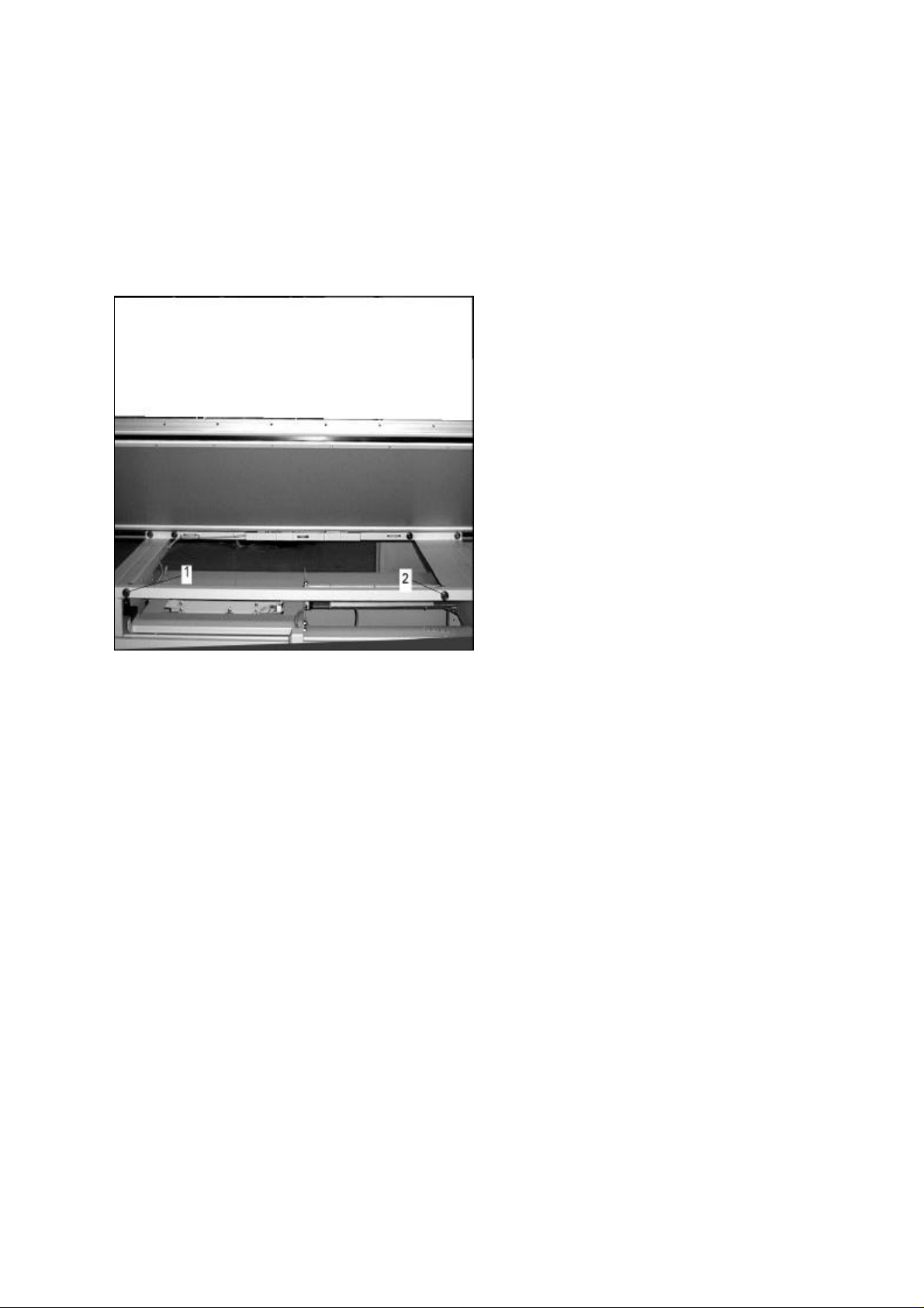
2.5.1 Mounting of Table Top in Small Rooms
Unscrew bumper stops (Fig.10, Item 1) from both ends of table top. Remove the two
bearings (Fig. 13, Item 1and 2) from the table frame . Place table top on table frame. Lift
table top on operator side to an angle of about 45 and hook profile rail on wallside
around the two plastic rollers. Then lower table top on operator side carefully. Slide table
top sideways in order to remount the bearings. Readjust bearings (eccentrics) for optimal
table top movement. Refasten bumper stops (Fig. 10, item 1) to table top ends.
Fig. 13
2.6 Function checking
Switch on generator and check all functions. If necessary make adjustments according to
chapter 3. Adjustment.
2.7 Mounting of Trim Covers
Install lower cover (Fig.2, Item 5), connecting bar (Item 3) and upper cover (Fig.2, Item 2).
0627 7226 18 von 34 07/98
Rev. 02 © 1998 Hans Pausch Röntgengerätebau Graf-Zeppelin-Str. 1 D-91056 Erlangen ALL RIGHTS RESERVED Ru
Page 19

3. ADJUSTMENTS
3.1 Exposure Height Adjustment
To adjust exposure height, remove covers (Fig. 1/Item 2) and (Fig. 2/Item 5).
Drive to the pre-set exposure position, then drive to the desired exposure position.
To change the pre-set value turn on Adjusting screw -R4: cw = upwards, ccw = downwards.
The new exposure position is reached when LED -V14 lights up.
The nominal value can be measured on -X16:9; approx. 8,6 V
Drive several times to exposure height and check exposure position; readjust if necessary.
A difference in the exposure height when driving from top to bottom or bottom to top can be
adjusted on Adjusting screw -R5. Switch on the unit and perform functional checking as
described under 4.2
3.2 Adjustment of Electronics
Adjust height potentiometer -R1 in that way that you have a half turn left of the
potentiometer in the top and in the bottom position.
Table adjustment max. at the top:
Drive the table upwards and stop just before reaching the safety limit switch -S4. Make
adjustment with Adjusting screw -R2 so that LED V12 is just about to light up. Drive to
upper position several times and correct settings - if necessary - on Adjusting screw -R2 .
(cw = upwards, ccw = downwards). The nominal value can be measured on -X16:7;
approx. 11V.
Table adjustment max. at the bottom:
Drive the table downwards and stop just before reaching the safety switch limit switch -S4.
Make adjustment with Adjusting screw -R6 so that LED V16 is just about to light up. Drive
to bottom end position several times and correct settings - if necessary - on Adjusting
screw -R6 . (cw = upwards, ccw = downwards). The nominal value can be measured on X16:11; approx. 1,65V.
Exposure height:
Drive to the preset exposure position, then drive to the desired exposure position.
Change setting value on Adjusting screw -R4: cw = upwards resp. Ccw = down wards.
LED -V14 is showing the reached exposure position.
The nominal value can be measured on -X19:9; drive to approx. 8,6 V exposure
height several times and control exposure position; readjust if necessary.
The different exposure height when driving upwards resp. downwards can be balanced on
Adjusting screw -R5.
The nominal value can be measured on -X19:10; approx. 0,18V
Slow motion range adjustment
On Adjusting screw -R7, the time for the slow down or slow stop speed for the table drive
and for the exposure height can be adjusted. cw = increase of slow down speed; ccw =
07/98 19 von 34 0627 7226
Rev. 02 ©1998 Hans Pausch Röntgengerätebau Graf-Zeppelin-Str. 1 D-91056 Erlangen ALL RIGHTS RESERVED Ru
Page 20

decrease of slow down speed. -V17s illuminated during slow down speed. Check Point: X16:12; approx. 0,55 V
Slow motion time adjustment
If table movement is actuated it will start with a slow motion speed; after the pre-set time
the movement will go to fast motion. The time can be adjusted on Adjusting screw -R8. cw =
longer period of time ccw = shorter period of time. Slow motion period is shown on LED V18. Check point: -X16:13; approx. 0,5 sec.
3.3 Adjustment of the Bucky in lateral direction
Loosen the screws (Fig. 9/ Item 1) from the four mounting brackets. Adjust the Bucky in
lateral direction if alignment to X-ray field is off and fasten afterwards the four screws again.
0627 7226 20 von 34 07/98
Rev. 02 © 1998 Hans Pausch Röntgengerätebau Graf-Zeppelin-Str. 1 D-91056 Erlangen ALL RIGHTS RESERVED Ru
Page 21
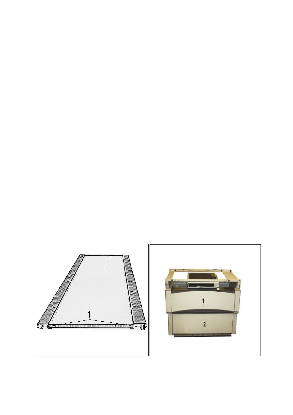
4. TECHNICAL MAINTENANCE
4.1 Mechanical and Electrical Checks
NOTE:
The maintenance schedule described below is to be accomplished at 12- month intervals.
Whenever in the course of these procedures, parts of the unit must be moved
electromotively, or if functional Checks require power, disconnect the power as soon as the
part has reached the new position, or after the appropriate functional test sequence.
Defective parts must be replaced by genuine spare parts according to spare part lists
enclosed.
Use only non-acid grease for maintenance. Do not grease or oil ball bearings with sealing
washers.
Preparations: Check the Elevator-2 of damages or missing parts.
Check all cables upon damage especially on the connectors and
strain relive points.
If necessary replace or repair as far as possible after consultation with
the customer.
Check cable loops of sufficient length.
Check all covers and trim covers. If necessary replace damaged parts
or make arrangement for exchange.
Check travelling range of equipment for obstacles. Inform the user .
Tools: Normal assembly tools, torque wrench, water level, spring scale,
feeler gauge, cleansing agent, grease.
Task: Switch off equipment
Dismount bumper and stop (Fig.15/Item 1+2) at either end of the table
top .
Fig. 15 Fig. 16
07/98 21 von 34 0627 7226
Rev. 02 ©1998 Hans Pausch Röntgengerätebau Graf-Zeppelin-Str. 1 D-91056 Erlangen ALL RIGHTS RESERVED Ru
Page 22
Take out table top and lay aside securely.
Dismount front cover (Fig. 16/Item 1+2)
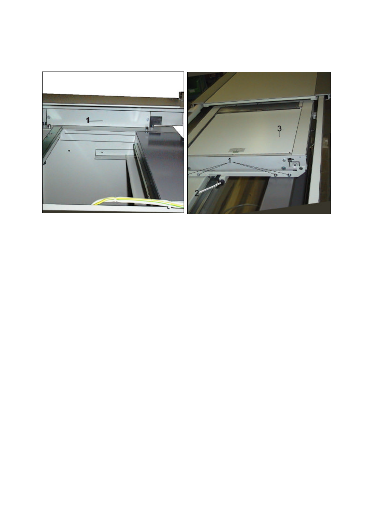
Remove cover left and right (Fig. 17/Item 1).
Fig. 17 Fig. 18
Floor mounting: Check firmness of anchor bolts. Tighten, if loose, at a torque of 50 Nm
(5 mkp).
Bucky carriage: Check performance of Bucky carriage over entire travel range.
Running noise ?
Determine defective bearings. Replace if necessary.
Clean guide rail and bearings and grease lightly.
Check the gap of the bearings and if necessary adjust eccentric
bearing (Fig. 18/Item 1).
Proper adjustment: The bearings can still be rotated by hand.
Check bumpers (Fig. 18/Item 2) on firmness and damage.
Switch-on equipment. Check function of brake (Fig. 18/Item 3) and
adjust if necessary.
Table frame: Remove the Covers (Fig. 17/Item 1) on the left and right side.
Clean left and right guide rails (Fig. 19/Item 1) and grease lightly.
Switch-on equipment. Check performance of lateral brakes
(Fig. 19/Item 2). Adjust if necessary.
Check bumper stops on both sides (Fig. 19/Item 4) on firmness and
damage. Remount the Covers (Fig. 17/Item 1) on the left and right
side.
0627 7226 22 von 34 07/98
Rev. 02 © 1998 Hans Pausch Röntgengerätebau Graf-Zeppelin-Str. 1 D-91056 Erlangen ALL RIGHTS RESERVED Ru
Page 23
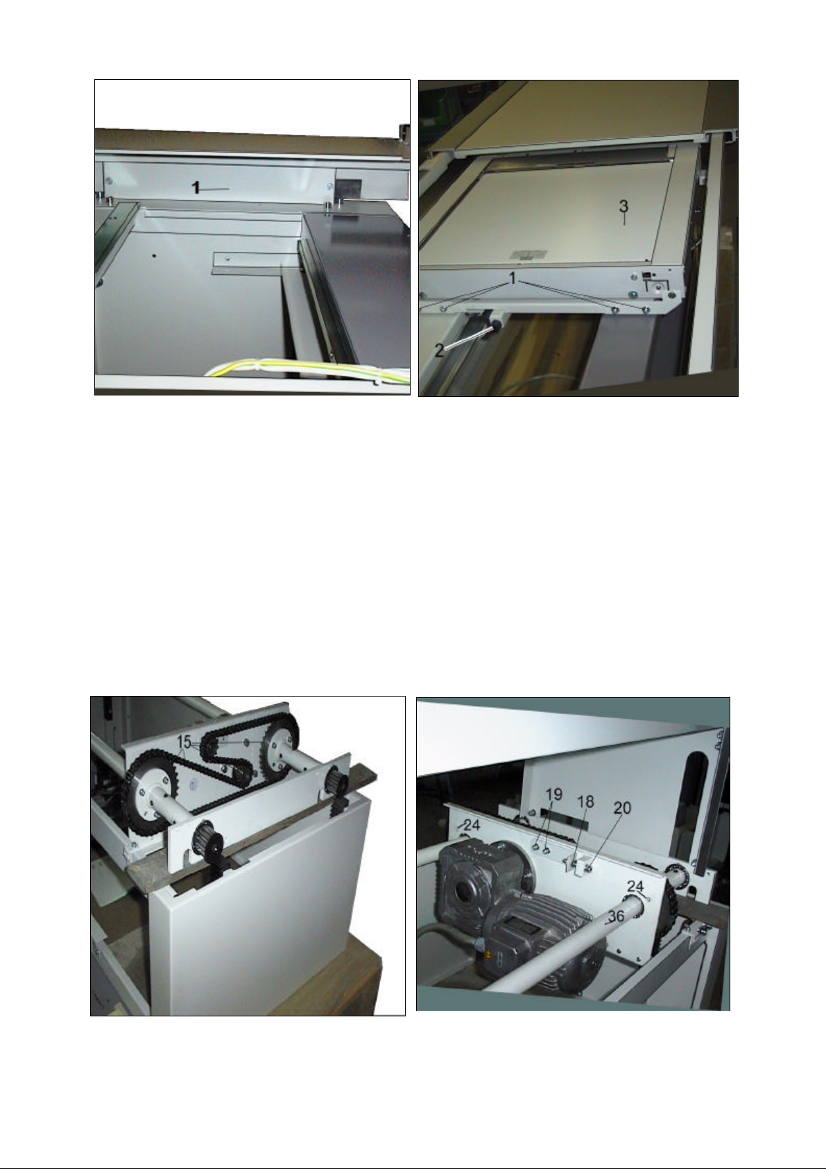
Fig. 19 Fig. 20
Table top: Remove table top.
Check plastic rollers (Fig. 20/Item 5) for trace of wear. Replace if
necessary.
Clean and check all ball bearings for table top movements on smooth
running and damage. Replace and grease if necessary.
Clean guide profiles of the table top.
Insert table top. Move over entire travel range. Running noise?
Smooth running? Adjust bearings with eccentric (Fig. 20/Item 6) if
necessary.
Switch-on equipment. Check performance of longitudinal brake (Fig.
20/Item 7).
Replace brake magnet if necessary.
Fig. 21 Fig. 22
07/98 23 von 34 0627 7226
Rev. 02 ©1998 Hans Pausch Röntgengerätebau Graf-Zeppelin-Str. 1 D-91056 Erlangen ALL RIGHTS RESERVED Ru
Page 24
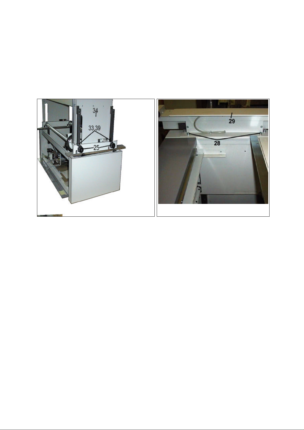
Remount bumper and stop (Fig 15/Item 1+2) to table top.
Hoisting motor: Check chain and sprocket wheels (Fig. 21/Item 15) for trace and wear.
Perform a test run if necessary.
Check chain tension. It should be taut. To adjust: Loosen counter nut
(Fig. 22/Item 18). Loosen screws (Item 19).
Adjust chain with clamping stud (Item 20). Counter lock clamping stud.
Tighten screws (Item 19)
Check all motor suspension bolts on firm seating.
Fig. 23 Fig. 24
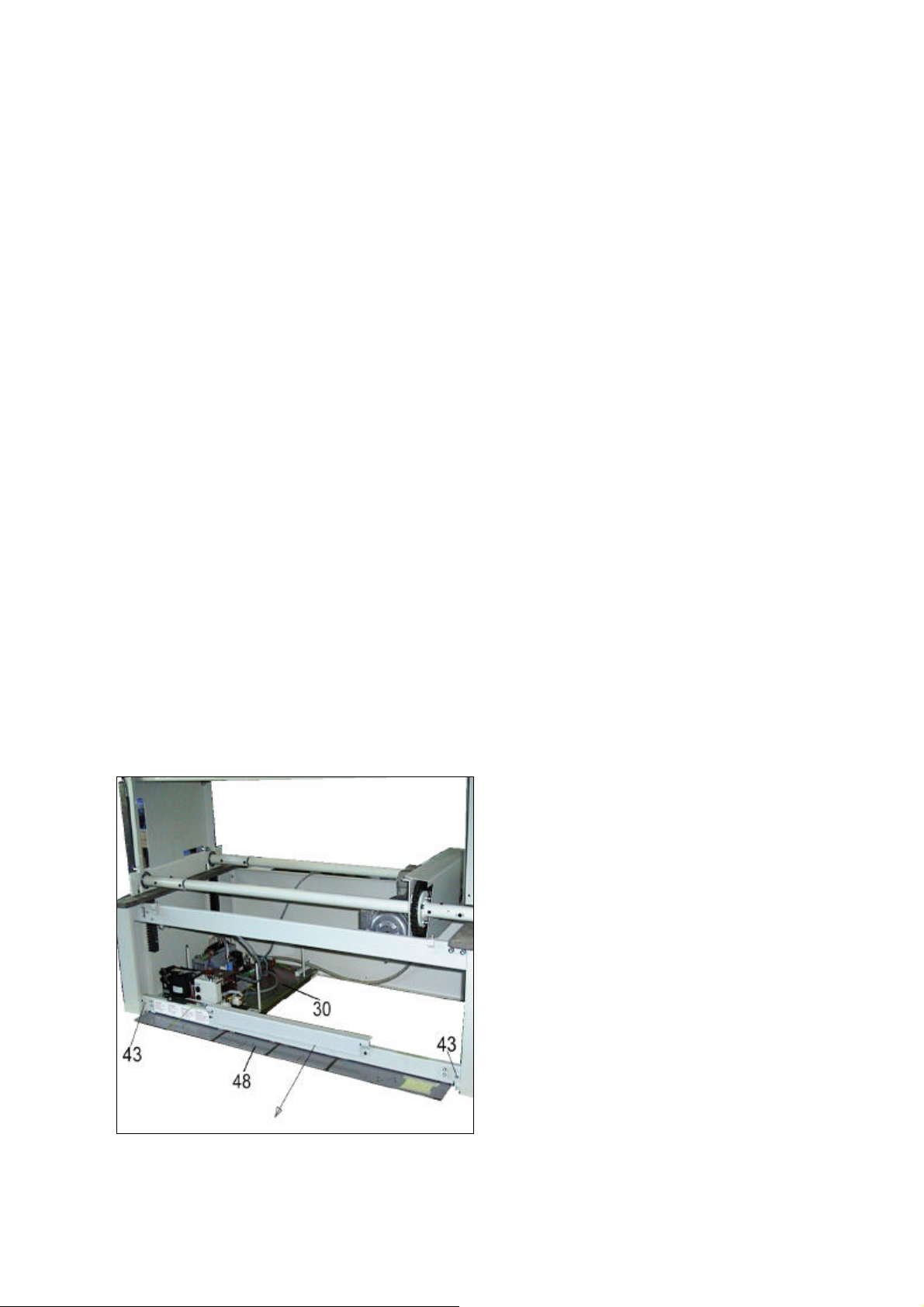
Toothed Racks, Drive Shafts, Pinions:
Switch on the unit. Run through entire travel range several times.
Listen for hard knocking noises. Switch-off the unit. Check the 8 racks
(Fig. 23/Item 25) and 4 pinions for wear. Use a mirror for visual
checking.
Any hard knocking running noise or visible damage ?
If not, regressed toothed racks and all bearings
If there are knocking noises or mechanical damage:
Remove the right and left plug.
Remove 4 socket cap screws on both sides (Fig. 24/Item 28).
Lift off table frame (Fig. 24/Item 29).
Remove plug (bottom of Bucky carriage) (wallside).
Remove plug on component board.
Remove cable strain relieve.
Lift off outer jacket (Fig. 22/Item ) by pulling upward uniformly. Do
not use force !
Caution: The Bucky carriage is not locked !
Remove 4 screws (Fig. 23/Item ) and bushings.
Crank up jacket support (Fig. 23/Item ) all the way up and lift it off
with drive assembly (Fig. 22/Item ). Arrange wooden bars (Fig. 22).
0627 7226 24 von 34 07/98
Rev. 02 © 1998 Hans Pausch Röntgengerätebau Graf-Zeppelin-Str. 1 D-91056 Erlangen ALL RIGHTS RESERVED Ru
Page 25
Place support / drive assembly on bars.
Continue to crank up the jacket until it can be removed from drive
assembly.
Toothed racks, pinions and drive are now fully accessible. Replace
defective parts.
Note:
Before removing the chain or the sprocket wheels, insert the index
pins (Fig. 22/Item ) into drilled holes (Fig. 22/Item ) on motor support
and sprocket wheel flange.
Do not forget to remove the index pins afterwards.
Reassemble:
Place the jacket support (Fig. 23/Item ) with toothed racks on to the
pinions.
Crank in the jacket support until a measure of í 12 mm (Fig. 26,
detail) is reached.
Attach complete support/drive assembly to toothed racks of table
base frame (Fig. 23).
Crank in assembly approx. 10 cm. Insert 4 bushings (Fig. X/Item 39)
and fasten 4 screws (Fig. 23/Item 33).
Component board:
Disconnect power (fuse).
Check with voltmeter that power is really off !
Tighten screws of all wire connections.
Check all components on firm seating. Tighten screws of necessary.
Note:
For better access the component board (Fig. 25/Item ) together with
the foot switches (Item ) can be pulled out.
For this, loosen 2 screws (Fig. 25/Item 43) and pull out forward (arrow)
the complete component group.
General: Reinstall covers
Clean the unit
Connect the power
Fig. 25
07/98 25 von 34 0627 7226
Rev. 02 ©1998 Hans Pausch Röntgengerätebau Graf-Zeppelin-Str. 1 D-91056 Erlangen ALL RIGHTS RESERVED Ru
Page 26

4.2 Functional Checks
Vertical Travel Mechanism:
- Turn on unit. Check performance of raising/lowering mechanism over entire
travel range:
- Automatic stop in bottom/top end positions as well as in pre-set exposure
position?
- Soft start and slow down of hoisting motor?
- Accurate performance of Foot switch ?
- Accurate performance of safety switch?
- Proper spring suspension of switches?
- No brushing of outer jacket against base panelling?
- No automatic lowering at load?
Table Top:
- Check performance of floating table top over entire travel range
both longitudinally and transversely:
- Moving smoothly? Running without noise?
- Buffered stops for longitudinal/lateral movements?
- No tendency to self-positioning?
- Accurate braking in working position?
- Accurate releasing of brake?
- Accurate performance of foot switch resp. of safety switch?
- Proper spring suspension of switches?
Bucky Carriage:
- Check performance of Bucky carriage over entire travel range.
- Moving smoothly?
- Running without noise?
- Accurate breaking in any working position?
- Accurate releasing of brake?
- Easy cassette insertion?
- Easy operation of cassette clamping device?
Exposure Release:
- Drive to exposure position. Be careful to observe radiation protection
measures.
- Trigger exposure.
- Exposure taken ?
- Change height to a position outside exposure position.
- Try exposure.
- No exposure?
0627 7226 26 von 34 07/98
Rev. 02 © 1998 Hans Pausch Röntgengerätebau Graf-Zeppelin-Str. 1 D-91056 Erlangen ALL RIGHTS RESERVED Ru
Page 27
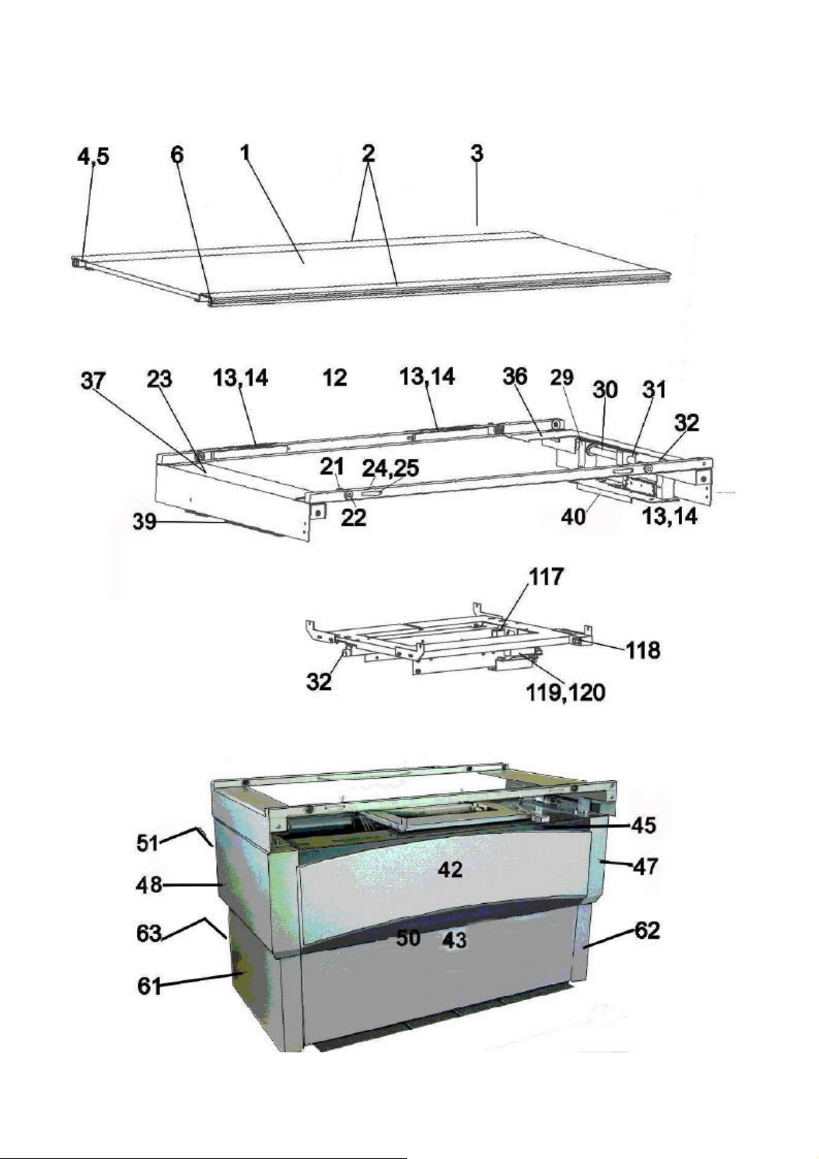
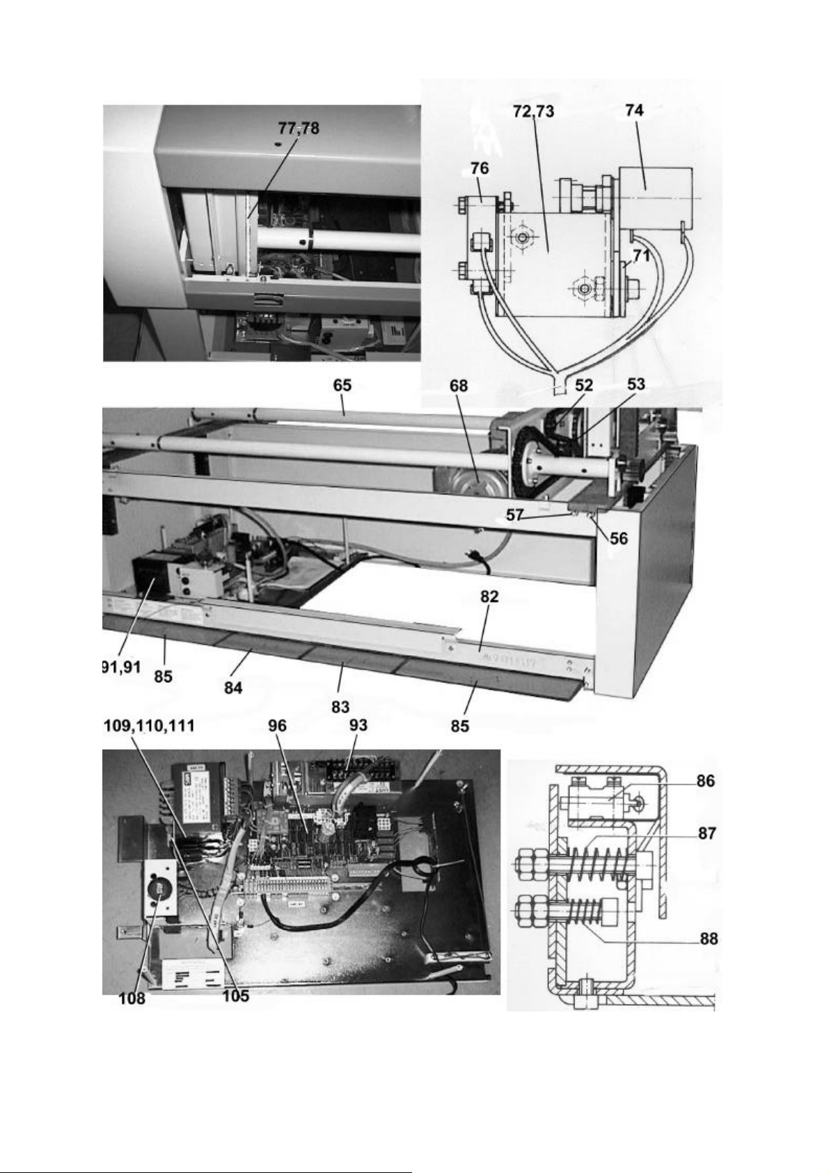
4.3 Spare Parts Table
07/98 27 von 34 0627 7226
Rev. 02 ©1998 Hans Pausch Röntgengerätebau Graf-Zeppelin-Str. 1 D-91056 Erlangen ALL RIGHTS RESERVED Ru
Page 28
0627 7226 28 von 34 07/98
Rev. 02 © 1998 Hans Pausch Röntgengerätebau Graf-Zeppelin-Str. 1 D-91056 Erlangen ALL RIGHTS RESERVED Ru
Page 29

4.4 Spare Parts List
Designation / Order No.
NOTE:
Defective parts must only be replaced by genuine spare parts as listed below. For
shipment of spare parts, always specify serial number of equipment and full ordering
number(s). Parts or part assemblies may only be replaced by the manufacturer or parties
expressly authorized. See also chapter on "Safety Procedures".
Item Designation Ordering No.
1 Table top 0622 0548
2 Profile rail 0622 0549
3 Frame 0622 0541
4 Stop 0622 0550a
5 Bumper 0005 0164g
6 Stop 0622 0550b
7
8
9
10
11
12 Frame 0622 0501
13 Solenoid 0006 0603
14 Laminated Spring 0622 0531
15
16
17
18
19
20
21 Bearing with bushing 0622 0556
22 Bearing with eccentric 0622 0555
23 Bearing with bushing 0622 0557
24 Shaft 0622 0515
25 Plastic roller 0622 0514
26
27
28
29 Bearing block 0622 0085a
30 Guide shaft 0622 0528
31 Bearing Block 0622 0522b
32 Bumper 0005 0108
33 Bearing LBAR 20 0005 0191a
34 Snap ring 32x1.5 DIN 471 2200 0223
35
36 Cover 0622 0523
37 Cover 0622 0526
38
07/98 29 von 34 0627 7226
Rev. 02 ©1998 Hans Pausch Röntgengerätebau Graf-Zeppelin-Str. 1 D-91056 Erlangen ALL RIGHTS RESERVED Ru
Page 30

Item Designation Ordering No.
39 Bridge 0627 0828a
40 Bridge 0627 0828b
41
42 Cover panel, Front 0627 0845
43 Cover panel 0627 0839a
44
45 Bridge, Front 0627 0834
46 Bridge, Rear 0627 0156a
47 Outer Side Panel 0627 0830a
48 Outer Side Panel 0627 0830b
49
50 Bridge, Front 0627 0835
51 Cover, rear 0627 0836
52 Track-connecting tool 0627 1244
53 Chain 2300 0027
54
55
56 Bearing with eccentric Bushing 0627 0119
57 Bushing 0627 0140
58 Cable Protection Cover 0627 1265
59
60
61 Side frame 0627 1155a
62 Side frame 0627 1155b
63 Back cover 0627 1152
64
65 Toothed Rack Drive II 0627 1200
66
67
68 Drive Motor (230 V) comp. 0627 1205
69
70
71 Terminal strip 0627 1334
72 Height measuring unit 0627 1130
73 Holder for Potentiometer 0627 1133
74 Potentiometer, Cpl. 0627 1136
75
76 Switch with lever 0006 0616ba
77 Rackholder 0627 1320
78 Toothed Rack 0627 1330
79 Crank Handle 0627 1325
80 Eccentric Bushing Comp. 0627 0034
81
82 Foot pedal switch, Comp. 0627 1140
83 Foot pedal switch, Short, "Up" 0627 1148
84 Foot pedal switch, Short, "Down"0627 1146
85 Foot pedal switch "Brake" 0627 1144
86 Switch 0006 0079a
87 D-spring 0005 0042s
88 D-spring 0005 0042t
89
0627 7226 30 von 34 07/98
Rev. 02 © 1998 Hans Pausch Röntgengerätebau Graf-Zeppelin-Str. 1 D-91056 Erlangen ALL RIGHTS RESERVED Ru
Page 31

Item Designation Ordering No.
90 Transformer (230 V) 0627 1470
91 Transformer (115 V) 0627 1465
92
93 Frequency Converter 0627 1461
94
95 Component board Cpl. 0627 1450
96 Relay Board 0627 1460
97
98 Motor Relay 0006 0667
99 Relay 0006 0286b
100
101
102
103
104
105 Push button 0006 0084a
106
107 Cable tie 0322 0076
108 Service Switch 0006 0260
109 Fuse holder 0006 0144
110 Cap for 5x20 fuse 0006 0152a
111 Cap for 6,3x32 fuse 0006 0152b
112
113
114 Bearing with eccentric 0632 0653
115 Bearing with bushing 0632 0657
116
117 Bridge plug 0632 0307
118 Brake complete 0632 0615
119 Magnet 0006 0603
120 Spring 0632 0418
07/98 31 von 34 0627 7226
Rev. 02 ©1998 Hans Pausch Röntgengerätebau Graf-Zeppelin-Str. 1 D-91056 Erlangen ALL RIGHTS RESERVED Ru
Page 32
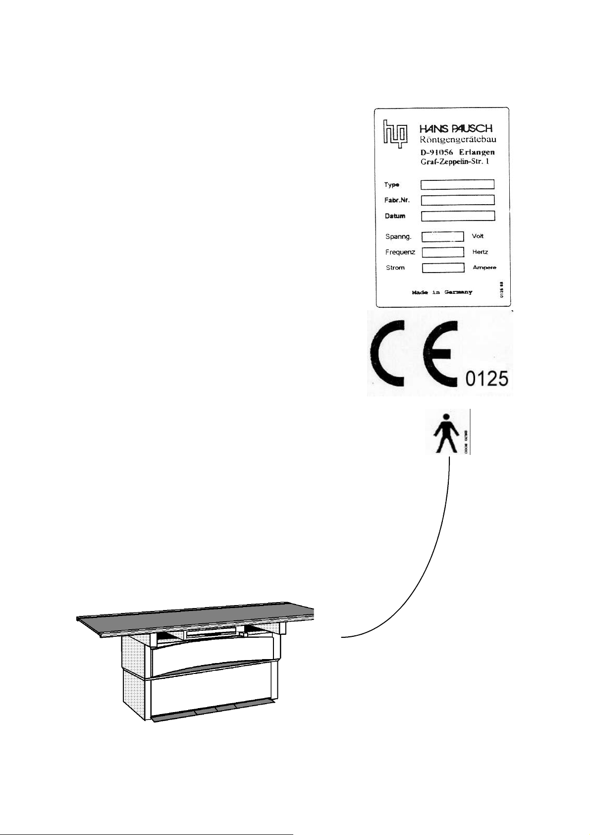
4.5 Name Plate Location:
0627 7226 32 von 34 07/98
Rev. 02 © 1998 Hans Pausch Röntgengerätebau Graf-Zeppelin-Str. 1 D-91056 Erlangen ALL RIGHTS RESERVED Ru
Page 33

4.6 Maintenance Documentation
The maintenance according to the attached maintenance instructions has been
carried out. Any parts replaced were original spare parts as shown on the list.
Replaced parts (List item no. only)
----------------------------------------------------------------------------------- Date Name of company Signature
Replaced parts (List item no. only)
----------------------------------------------------------------------------------- Date Name of company Signature
Replaced parts (List item no. only)
----------------------------------------------------------------------------------- Date Name of company Signature
Replaced parts (List item no. only)
---------------------------------------------------------------------------------- Date Name of company Signature
Replaced parts (List item no. only)
----------------------------------------------------------------------------------- Date Name of company Signature
Replaced parts (List item no. only)
---------------------------------------------------------------------------------- Date Name of company Signature
07/98 33 von 34 0627 7226
Rev. 02 ©1998 Hans Pausch Röntgengerätebau Graf-Zeppelin-Str. 1 D-91056 Erlangen ALL RIGHTS RESERVED Ru
Page 34

Subject to technical alterations TV / Ru
0627 7226 34 von 34 07/98
Rev. 02 © 1998 Hans Pausch Röntgengerätebau Graf-Zeppelin-Str. 1 D-91056 Erlangen ALL RIGHTS RESERVED Ru
 Loading...