

Page 1
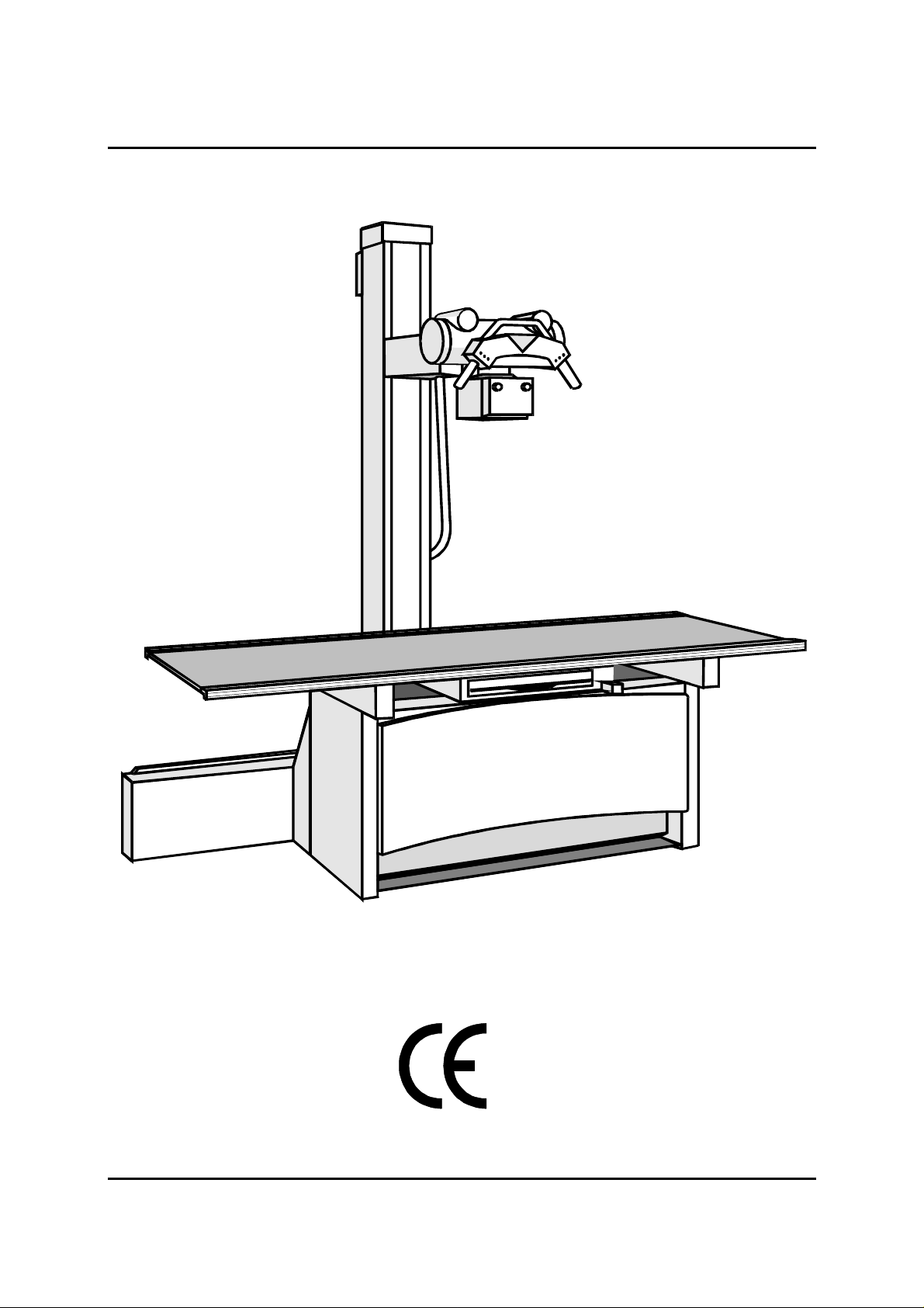
Mounting Instructions CS 2000
0125
English Edition
08/98 - 1 of 44- 0125 7221
Revision 02 © 1998 Hans Pausch Röntgengerätebau Graf-Zeppelin-Str. 1 D-91056 Erlangen ALL RIGHTS RESERVED Ru
Page 2

TABLE OF CONTENTS Sheet
1. Specification
1.1 General safety notes 3
1.2 Compatibility 3
1.3 Climatic conditions 3
1.4 Dimensions and weights 3
1.5 Component Designation 4
1.6 Dimensional Drawings 5
1.7 Dimensional Drawings/Floor Mounting 6
1.8 Installation of high tension cables 7
1.9 Constructional preparations 7
1.10 Necessary measuring means 7
1.11 Necessary special tools 7
1.12 Power supply data 7
1.13 Schematics 8
1.14 Component Numbers and Designation 14
2. Mounting of Unit
2.1 Unpack equipment parts 16
2.2 Assembly of the table and rail stand 17
2.3 Assembly of the column 18
2.4 Assembly of Bucky 19
2.5 Assembly of the table plate 20
2.5.1 Assembly of the table plate 21
2.6 Assembly of the tube and collimator 21
2.7 Assembly of the tube holding support 23
2.8 Assembly of the tube on tube holding support 23
2.9 Assembly of the control arm 24
2.10 Assembly and installation of the cable 25
2.11 Counterweight on the column 25
2.12 Function control 26
2.13 Assembly of covers 26
3. Adjustments
3.1 Adjustment of the column vertical 28
3.2 Adjustment of the column in direction of rotation 28
3.3 Adjustment of the rotational axis respectively the
supporting arm 29
3.4 Adjustment of the rotation detent (0° , 90 °) 29
3.5 Adjustment of the Bucky in table transverse direction 29
3.6 Adjustment of the vertical FFA switch 30
4.0 Technical Maintenance
4.1 Mechanical and electrical tests 31
4.2 Spare Parts Table 37
4.2.1 Spare Parts Column 38
4.3 Spare Parts List 40
4.4 Maintenance Documentation 43
4.5 Name Plate Location 44
0125 7221 - 2 of 44- 08/98
Revision 02 © 1998 Hans Pausch Röntgengerätebau Graf-Zeppelin-Str. 1 D-91056 Erlangen ALL RIGHTS RESERVED Ru
Page 3

1. Technical data
1.1 General safety notes
In the Federal Republic of Germany, the electrical installation of rooms for medical
purposes must conform to the provisions VDE Standard 0107. In all other countries
the national requirements have to be observed.
Check the installation layout plan.
During the installation it is important to check that all protective ground wire
connections provided by the manufacturer are properly made before the equipment is
started up.
The protective ground wires between the individual system components and the
power supply have to be connected as shown in the wiring diagram.
Regulation of professional associations concerning safety and accident prevention
has to be observed. No work may be performed on parts carrying a voltage higher
than 42 V. If it is necessary to turn on the power for execution of movements of the
equipment in the course of installation procedure, it must be shut down immediately
after completion of these movements.
1.2 Compatibility
This mounting instruction is valid for CS 2000 and all versions of them.
The table carries all customary in trade Bucky units.
A Bucky Wall stand can be installed on the right or left side of the table depending on
the user side.
1.3 Climatic conditions
During regular work:
Temperature: 10° C to 40° C
Humidity: 20% to 80%
Air pressure: 700 hPA to 1100 hPa
During transport:
Temperature: -25° C to 70° C
Humidity: 5% to 95%
Air pressure: 600 hPA to 100 h PA
1.4 Dimensions and weights
of components Dimensions of components Weights
Table 1400x770x750 mm 120 kg
Table top 2200x810x 40 mm 35 kg
Column 2320x470x302 mm 155 kg
Rail stand 2250x183x302 mm 80 kg
Tube stand with vertical carriage 600x500x200 mm 22 kg
of collies Dimensions of collies Weights
Table 1530x860x960 mm 155 kg
Table top 2320x930x200 mm 56 kg
Column
Rail stand 2400x780x760 mm 330 kg
Tube stand with vertical carriage
08/98 - 3 of 44- 0125 7221
Revision 02 © 1998 Hans Pausch Röntgengerätebau Graf-Zeppelin-Str. 1 D-91056 Erlangen ALL RIGHTS RESERVED Ru
Page 4
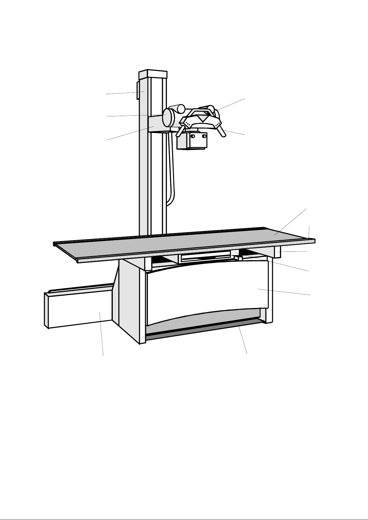
1.5 Component Designation
L
I
E
A
B
C
D
F G
A Table top, floating, manually movable, scratch-proof
B Profile rail with trim cover, smooth, accepts accessories
C Upper table frame
D Bucky unit, movable
E Table base, solid, vibration-free
F Guide rails for tube stand
G Foot treadle
H Vertical carriage with X-ray tube support arm
I Tube stand, rotatable
K X-ray tube
L Control arm
M Protractor
0125 7221 - 4 of 44- 08/98
Revision 02 © 1998 Hans Pausch Röntgengerätebau Graf-Zeppelin-Str. 1 D-91056 Erlangen ALL RIGHTS RESERVED Ru
Page 5
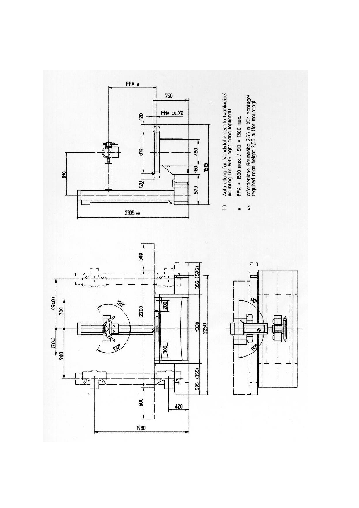
1.6 Dimensional Drawings
08/98 - 5 of 44- 0125 7221
Revision 02 © 1998 Hans Pausch Röntgengerätebau Graf-Zeppelin-Str. 1 D-91056 Erlangen ALL RIGHTS RESERVED Ru
Page 6
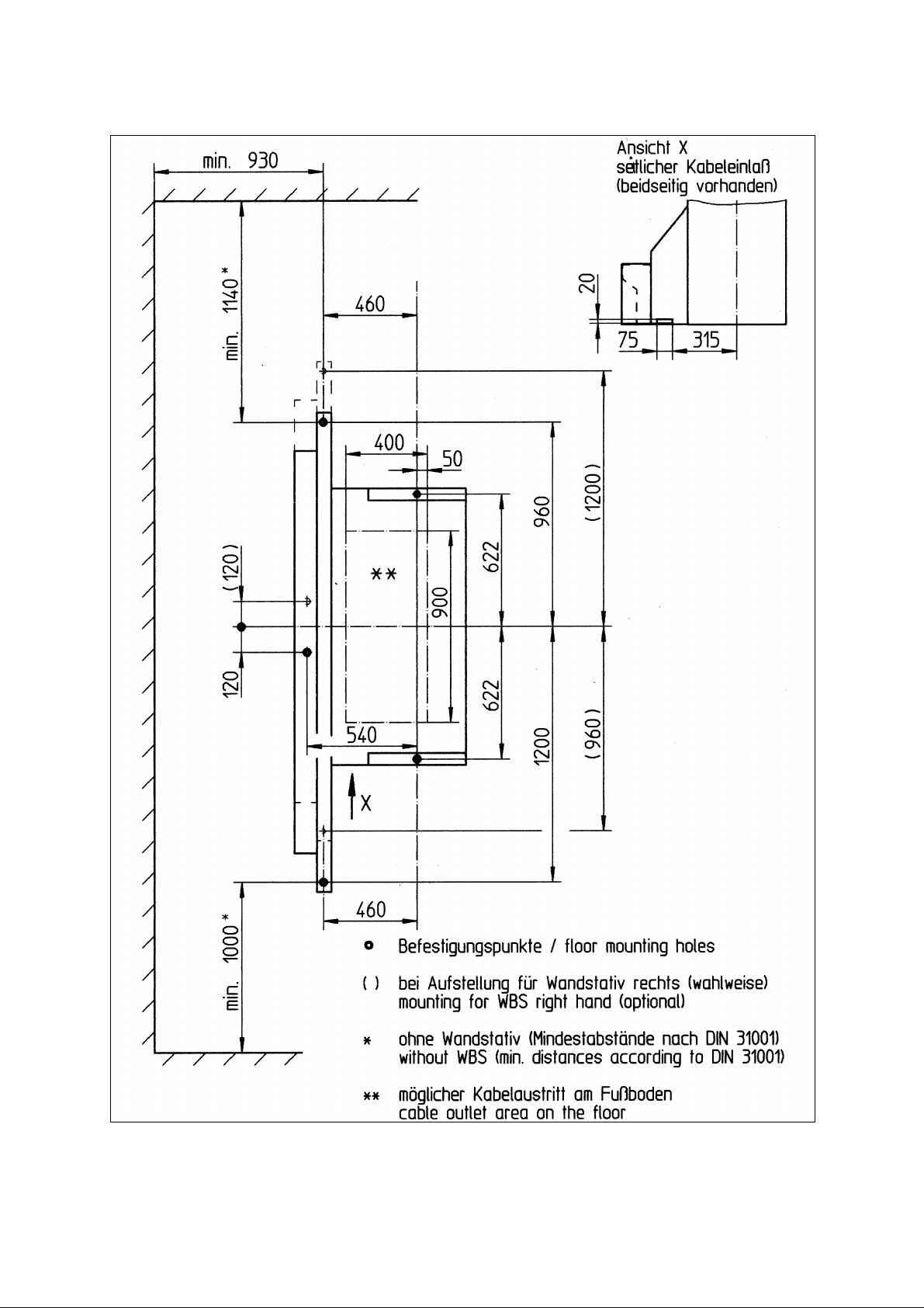
1.7 Dimensional Drawings/Floor Mounting
0125 7221 - 6 of 44- 08/98
Revision 02 © 1998 Hans Pausch Röntgengerätebau Graf-Zeppelin-Str. 1 D-91056 Erlangen ALL RIGHTS RESERVED Ru
Page 7
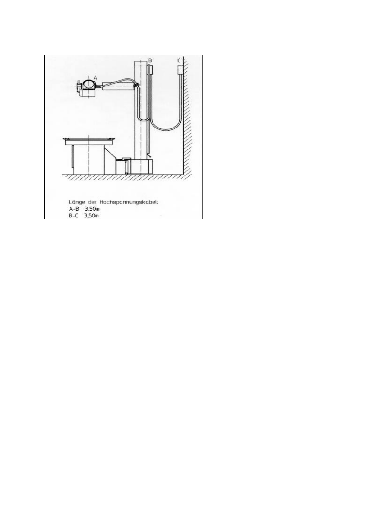
1.8 Installation of high tension cables
1.9 Constructional preparations
The electrical connection data have to correspond with the of the equipment supply
voltage.
For the CS 2000 is only a supply voltage of 115/230 V required and a corresponding
ground connection transmission. The mounting points of the CS 2000 have to support
a tractive power of 2500 N at each mounting point (concrete floor? B 150 DIN 1045
when using the included fastening material).
Prepare on the floor fastening bore-holes of 12 mm according to drawing 1.6., under
consideration of the construction.
The connection cable of the CS 2000, the Bucky and the detector has to be placed
constructional depending on the version until the terminal box in the table base or until
the Bucky according to the installation plan.
The optional ceiling- wall- terminal box can be mounted if required to the wall or
ceiling.
1.10 Necessary measuring means
Machine air level
1.11 Necessary special tools
Percussion bore machine
Rock drill 12 mm
Socket head cap key 6 mm and 4 mm shortened (is included)
1.12 Power supply data
Power supply: 115/230 V
Frequency: 50 / 60 Hz
Rated current: 2/1 A
Rated power supply voltage: 220 VA
08/98 - 7 of 44- 0125 7221
Revision 02 © 1998 Hans Pausch Röntgengerätebau Graf-Zeppelin-Str. 1 D-91056 Erlangen ALL RIGHTS RESERVED Ru
Page 8
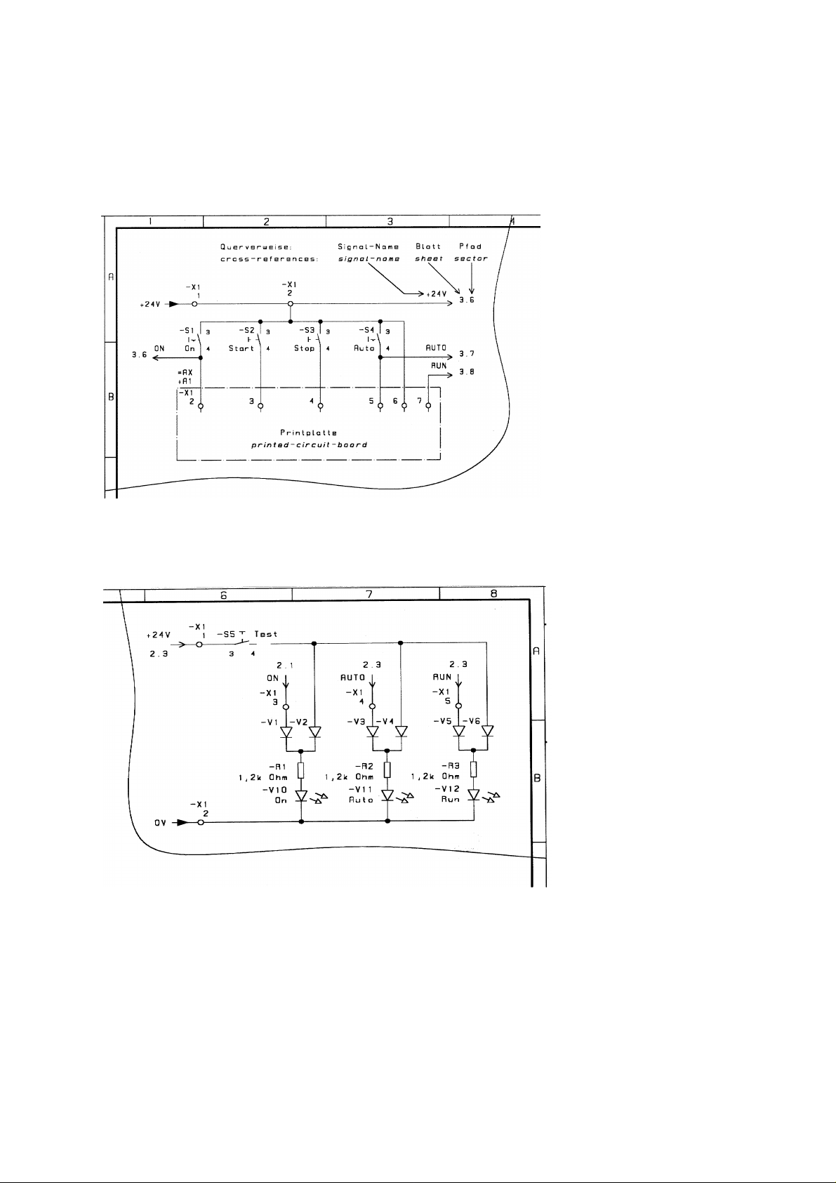
1.13 Schematics sheet 1
1.13.1 Description at Schematics
....... Schematics sheet 2
= AX control panel
= Unit, Indication
...... Schematics sheet 3
= AX control panel
= Unit, Indication
1.13.1 Table of contents at Schematics
Sheet 2 Schematics =AA
Sheet 3 Schematics =AB
Sheet 4 Schematics =AB
Sheet 5 Wiring diagram =AA
Sheet 6 Wiring diagram =AB
0125 7221 - 8 of 44- 08/98
Revision 02 © 1998 Hans Pausch Röntgengerätebau Graf-Zeppelin-Str. 1 D-91056 Erlangen ALL RIGHTS RESERVED Ru
Page 9
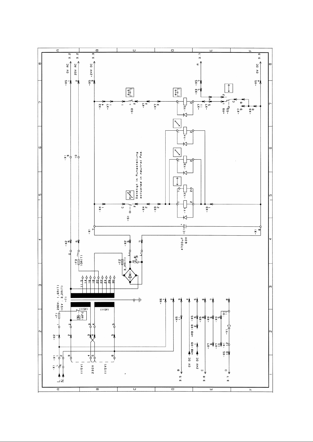
1.13 Schematics sheet 2
08/98 - 9 of 44- 0125 7221
Revision 02 © 1998 Hans Pausch Röntgengerätebau Graf-Zeppelin-Str. 1 D-91056 Erlangen ALL RIGHTS RESERVED Ru
Page 10
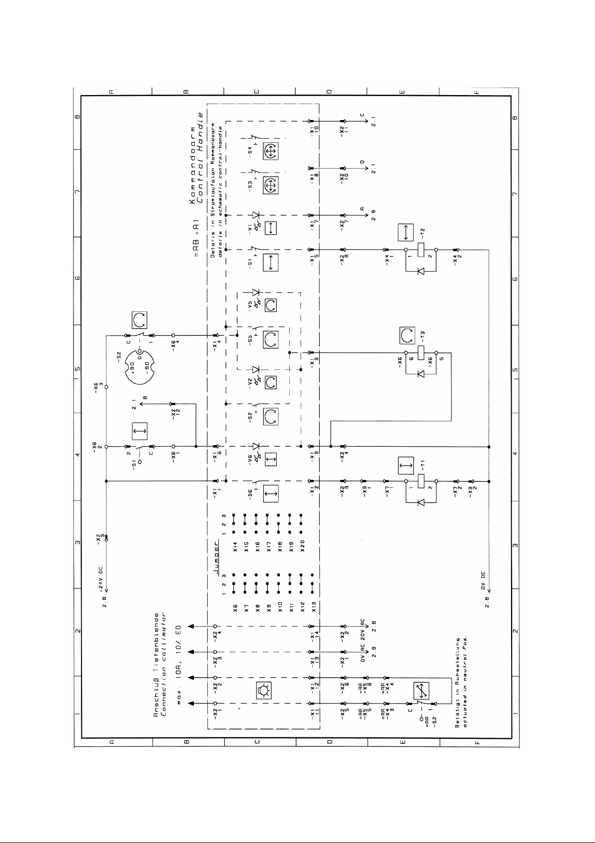
1.13 Schematics sheet 3
0125 7221 - 10 of 44- 08/98
Revision 02 © 1998 Hans Pausch Röntgengerätebau Graf-Zeppelin-Str. 1 D-91056 Erlangen ALL RIGHTS RESERVED Ru
Page 11
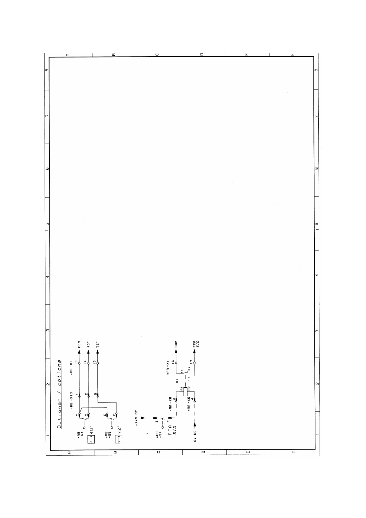
1.13 Schematics sheet 4
08/98 - 11 of 44- 0125 7221
Revision 02 © 1998 Hans Pausch Röntgengerätebau Graf-Zeppelin-Str. 1 D-91056 Erlangen ALL RIGHTS RESERVED Ru
Page 12
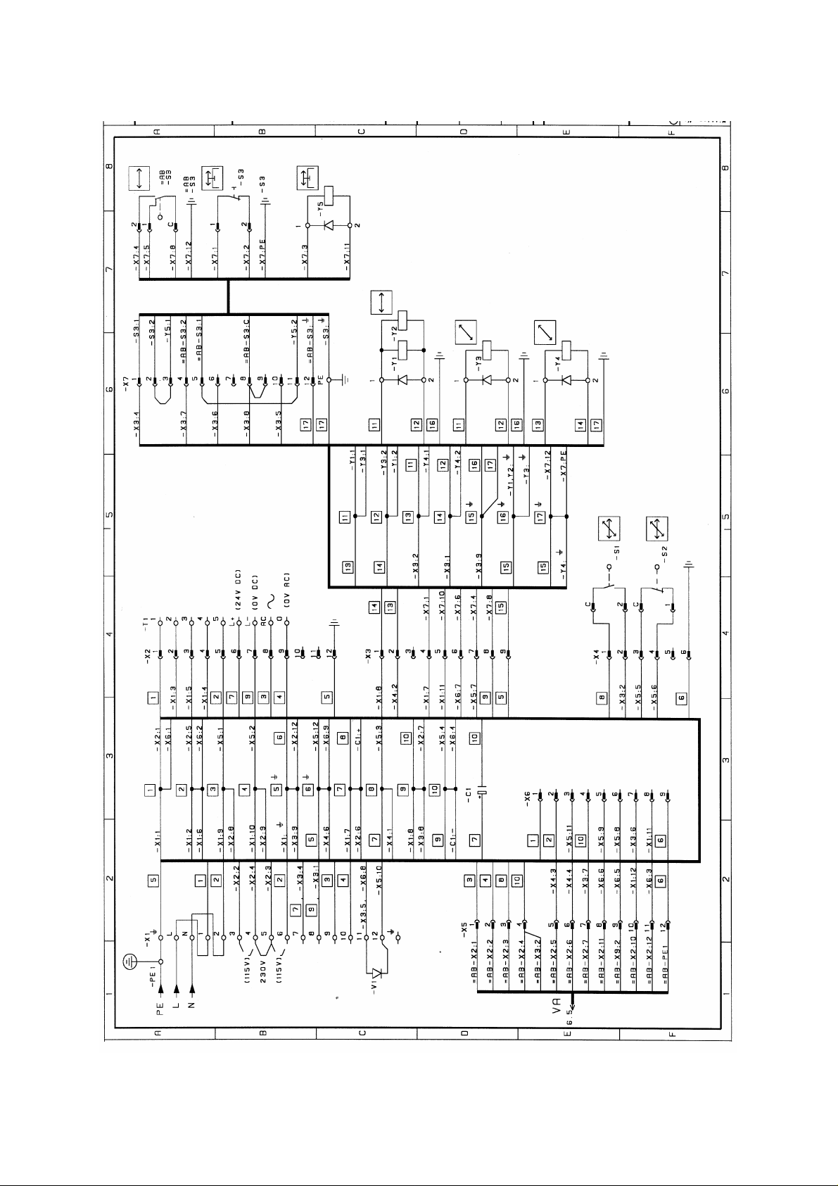
1.13 Wiring Diagram sheet 5
0125 7221 - 12 of 44- 08/98
Revision 02 © 1998 Hans Pausch Röntgengerätebau Graf-Zeppelin-Str. 1 D-91056 Erlangen ALL RIGHTS RESERVED Ru
Page 13
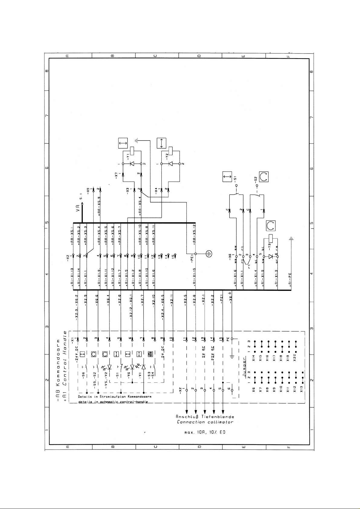
1.13 Wiring Diagram sheet 6
08/98 - 13 of 44- 0125 7221
Revision 02 © 1998 Hans Pausch Röntgengerätebau Graf-Zeppelin-Str. 1 D-91056 Erlangen ALL RIGHTS RESERVED Ru
Page 14

1.14 Description of components for circuit diagram sheet 1
=AA- Table
=AA-C1 By-pass condenser 24V DC
=AA-F1 Circuit fuse
=AA-F2 Fuse 24V DC
=AA-F3 Fuse 20VAC
=AA-PE1 Main earthing bolt
=AA-S1 Foot control brake release table top
=AA-S2 Foot control for collimator light
=AA-S3 Switch release Bucky brake
=AA-T1 Mains transformer
=AA-V1 Uncoupling diode
=AA-X1 Terminal strip
=AA-X2 Plug in connection power pack
=AA-X3 Plug in connection brake solenoid table top
=AA-X4 Plug in connection foot control
=AA-X5 Plug in connection Column
=AA-X6 Plug in connection Tomo
=AA-X7 Plug in connection Bucky brake
=AA-Y1 Brake solenoid table top longitudinal
=AA-Y2 Brake solenoid table top longitudinal
=AA-Y3 Brake solenoid table top transverse left
=AA-Y4 Brake solenoid table top transverse right
=AA-Y5 Brake solenoid for Bucky brake
=AB- Stand
=AB+A1 Control Arm
=AB+A1-X1 Plug-in connection control arm
=AB+A1-X2 Terminal strip for collimator
=AB+A1-X3 Terminal strip for option
=AB+A1-S1 Switch for horizontal brake release
=AB+A1-S2 Switch for rotational break release
=AB+A1-S3 Switch release all brakes
=AB+A1-S4 Switch release all brakes
=AB+A1-S5 Switch for rotational break release
=AB+A1-S6 Switch for vertical brake release
=AB+A1-V1 LED Stand - Bucky centring
=AB+A1-X2 LED - rotation angle 0°, +/-90°
=AB+A1-X3 LED - option
=AB+A1-X4 LED - option
=AB+A1-X5 LED - rotation angle 0°, +/-90°
=AB+A1-X6 LED - vertical FFD
0125 7221 - 14 of 44- 08/98
Revision 02 © 1998 Hans Pausch Röntgengerätebau Graf-Zeppelin-Str. 1 D-91056 Erlangen ALL RIGHTS RESERVED Ru
Page 15

1.14 Description of components for circuit diagram sheet 2
=AB-K1 Relay for optional FFD
=AB-PE Main earthing bolt Stand
=AB-S1 FFD switch vertical
=AB-S2 Switch tube rotation 0°, +/-90°
=AB-S3 Switch Bucky engaged
=AB-S4 FFD switch horizontal 40“
=AB-S5 FFD switch horizontal 72“
=AB-X2 Plug-in connection for tube support arm
=AB-X3 Plug-in connection for vertical brake
=AB-X4 Plug-in connection for horizontal brake
=AB-X5 Plug-in connection for collimator
=AB-X6 Terminal strip in the tube support arm
=AB-X7 Plug-in connection in vertical brake
=AB-X9 Plug-in connection for =AC-S3
=AB-X10 Plug-in connection for =AB-S4, -S5
=AB-Y1 Vertical brake
=AB-Y2 Horizontal brake
=AB
08/98 - 15 of 44- 0125 7221
Revision 02 © 1998 Hans Pausch Röntgengerätebau Graf-Zeppelin-Str. 1 D-91056 Erlangen ALL RIGHTS RESERVED Ru
Page 16
2. Mounting
2.1 Unpack equipment parts
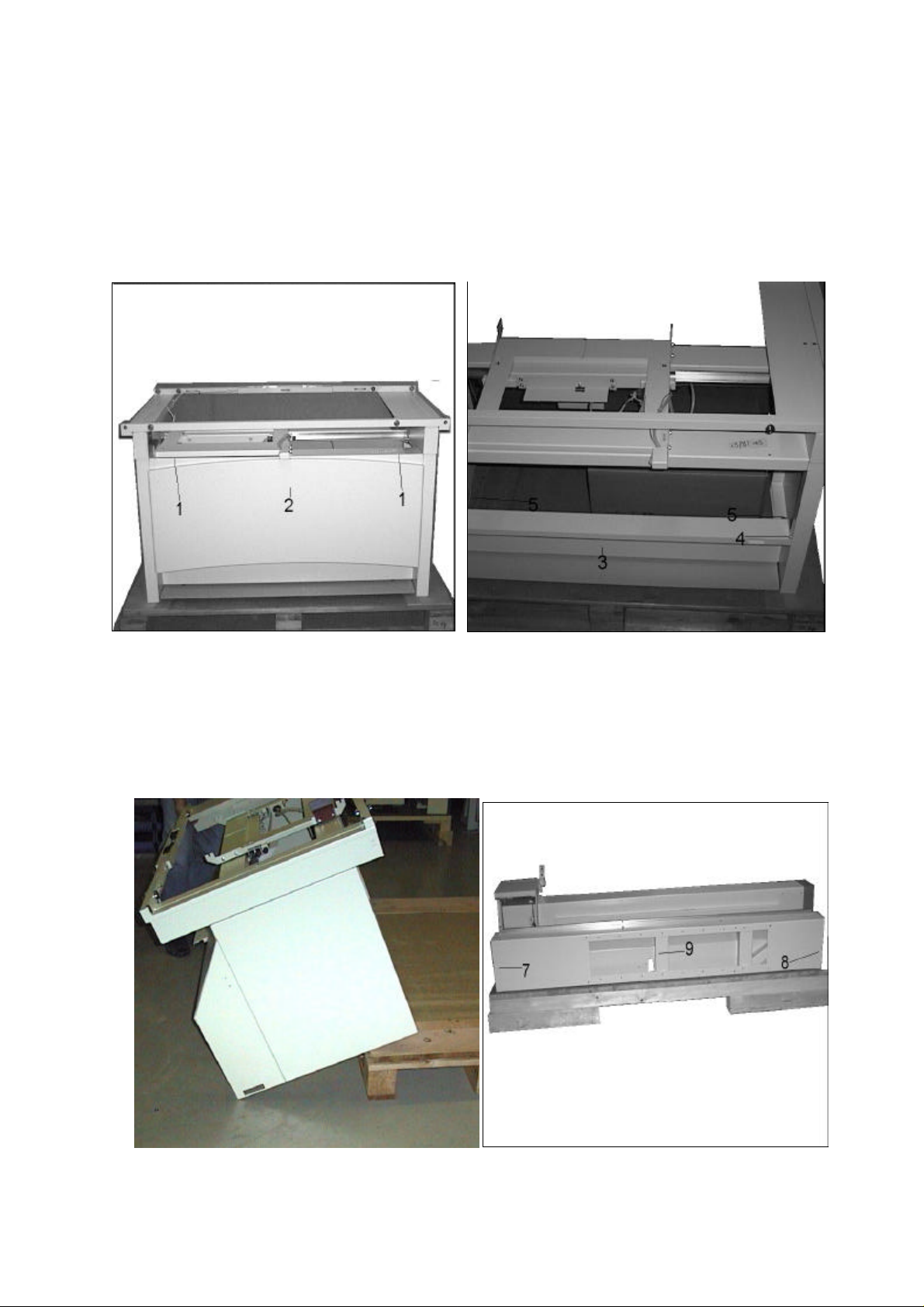
Remove table from the palette
In addition:
Remove both artificial caps (Fig. 1 Pos. 1) and loosen beneath the socket head cap
screw. Tilt front plate „above“ (Pos. 2) carefully to the outside and then take out from
underneath. Take out accessory box from the table.
Fig. 1 Fig. 2
Dismount the below placed table cover (Fig. 2/Pos. 3) with both screws (Pos.4).
Loosen both transport screws (Fig.2/Pos. 5) from the palette and push to the bottom.
Push the table to the back from the palette (Fig. 3). Tilt table to the back, pull out
palette to the front and take off the table carefully.
Fig. 3 Fig. 4
0125 7221 - 16 of 44- 08/98
Revision 02 © 1998 Hans Pausch Röntgengerätebau Graf-Zeppelin-Str. 1 D-91056 Erlangen ALL RIGHTS RESERVED Ru
Page 17
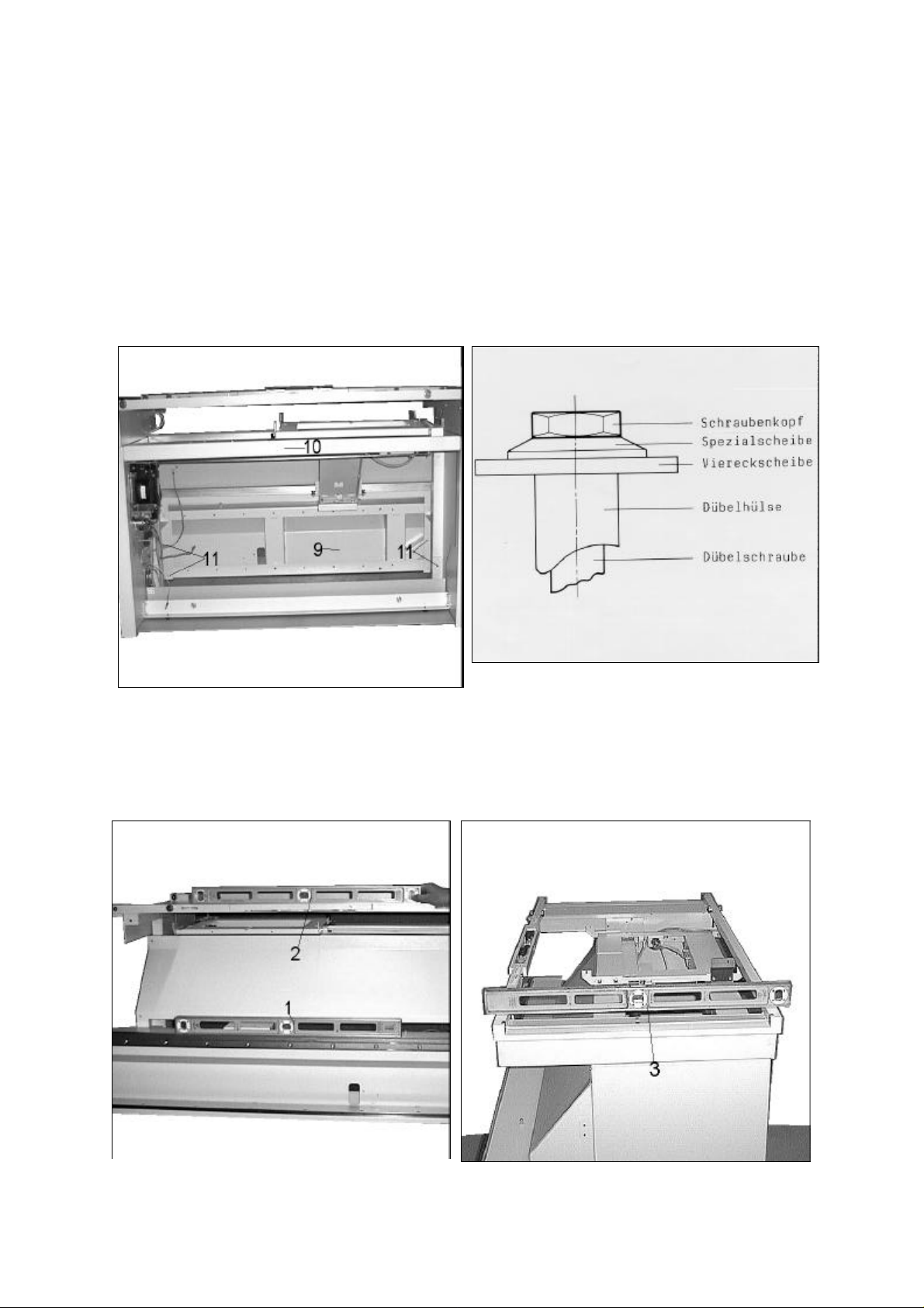
Dismount both closing caps (Fig. 4/Pos. 7 and 8) and loosen the transport security
screws of the rail stand, then push to the bottom. Remove rail stand from the palette
and take to the assembly area. Dismount transport security plates of the column.
(Leave column on the palette until assembly). Unpack equipment parts and check for
completeness according to shipping list respectively order. Check complete delivery
upon damage before assembly start.
2.2 Assembly of the table and rail stand
Take the table to assembly area. Place the rail stand behind the table. Align the rail
stand (Fig. 5/Pos.9) to the right or left side of the table (Pos. 10) depending on the
way of assembly (according to drawing for installation of a Bucky wall stand left or
right).
Fig. 5 Fig. 6
Fasten the rail stand with 4 screws (Pos. 11) to the table. Push table with rail stand
over the fastening bore-holes at the assembly place. Respectively align the table at
the assembly place, mark the 5 fastening bore-holes and bore. Insert the included set
pin (Fig. 6) and insert screws and washers.
Fig. 7 Fig. 8
08/98 - 17 of 44- 0125 7221
Revision 02 © 1998 Hans Pausch Röntgengerätebau Graf-Zeppelin-Str. 1 D-91056 Erlangen ALL RIGHTS RESERVED Ru
Page 18
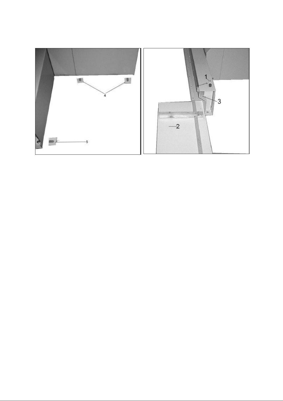
Align table with rail stand according to air level (Fig. 7 Pos. 1,2 and Fig. 8/Pos. 3). If
necessary, align with washers (Fig. 9/Pos. 4 and 5). Fasten all screws tightly.
Fig. 9 Fig. 10
2.3 Assembly of the column
The column will be shipped with inserted counterweights. The counterweight in the
column is secured for the transport with two screws.
Attention:
Remove transport security not before assembly of the tube and collimator.
To insert the column into the rail stand easily, an assembly plate is included to the
shipment. It is constructed so that it can slide on a normal floor easily.
Dismount limit stop (Fig. 10 Pos. 1) from the rail stand.
Set up (Fig. 11/Pos. 1) and place on the assembly plate (Pos. 2). Push the assembly
plate to the rail stand and align (Fig. 11/Pos. 2). Insert the column from the assembly
plate into the rail stand.
Remark:
When inserting pay attention the bearing and brake magnet.
Mount the limit stop (Fig. 10/Pos. 1) again to the rail stand.
0125 7221 - 18 of 44- 08/98
Revision 02 © 1998 Hans Pausch Röntgengerätebau Graf-Zeppelin-Str. 1 D-91056 Erlangen ALL RIGHTS RESERVED Ru
Page 19
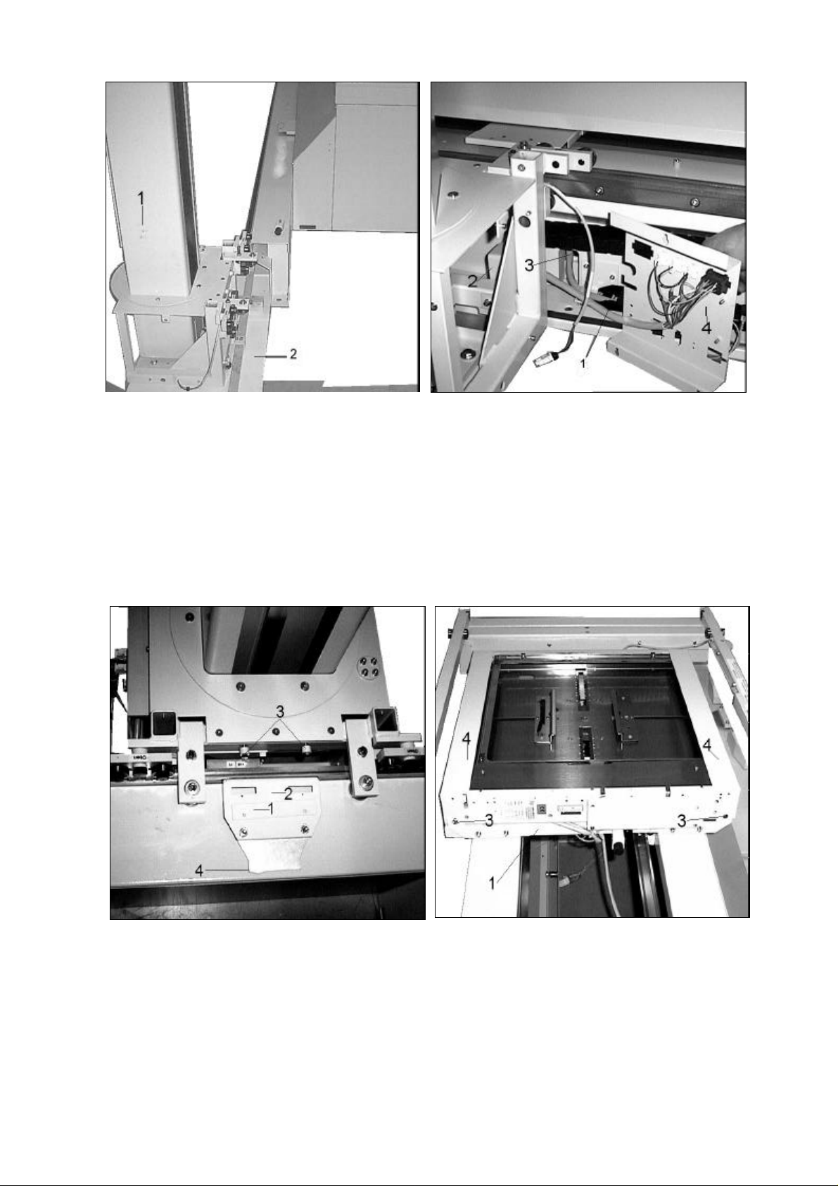
Fig. 11 Fig. 12
Mount the cable guide chain (Fig. 12/Pos. 1) to the rail stand - back wall - and to the
column carriage (Pos. 2). Insert the end of the cable (Pos. 3) into the table. Mount the
distributing plate (Pos. 4) to the column carriage.
Dismount cover (Fig. 13/Pos. 1) from the catch (Pos. 2). Loosen both screws (Pos. 3)
and mount the catch.
Attention: The catch has to be adjusted in height direction so that the switch nose
(Pos. 4) is centred to the switch spring of the column Bucky coupling.
.
Fig. 13 Fig. 14
2.4 Assembly of Bucky
Remark:
Buckys of different manufacturers can be installed. The equipment will be prepared
according to the order and the necessary fastening materials will be included to the
shipment.
08/98 - 19 of 44- 0125 7221
Revision 02 © 1998 Hans Pausch Röntgengerätebau Graf-Zeppelin-Str. 1 D-91056 Erlangen ALL RIGHTS RESERVED Ru
Page 20
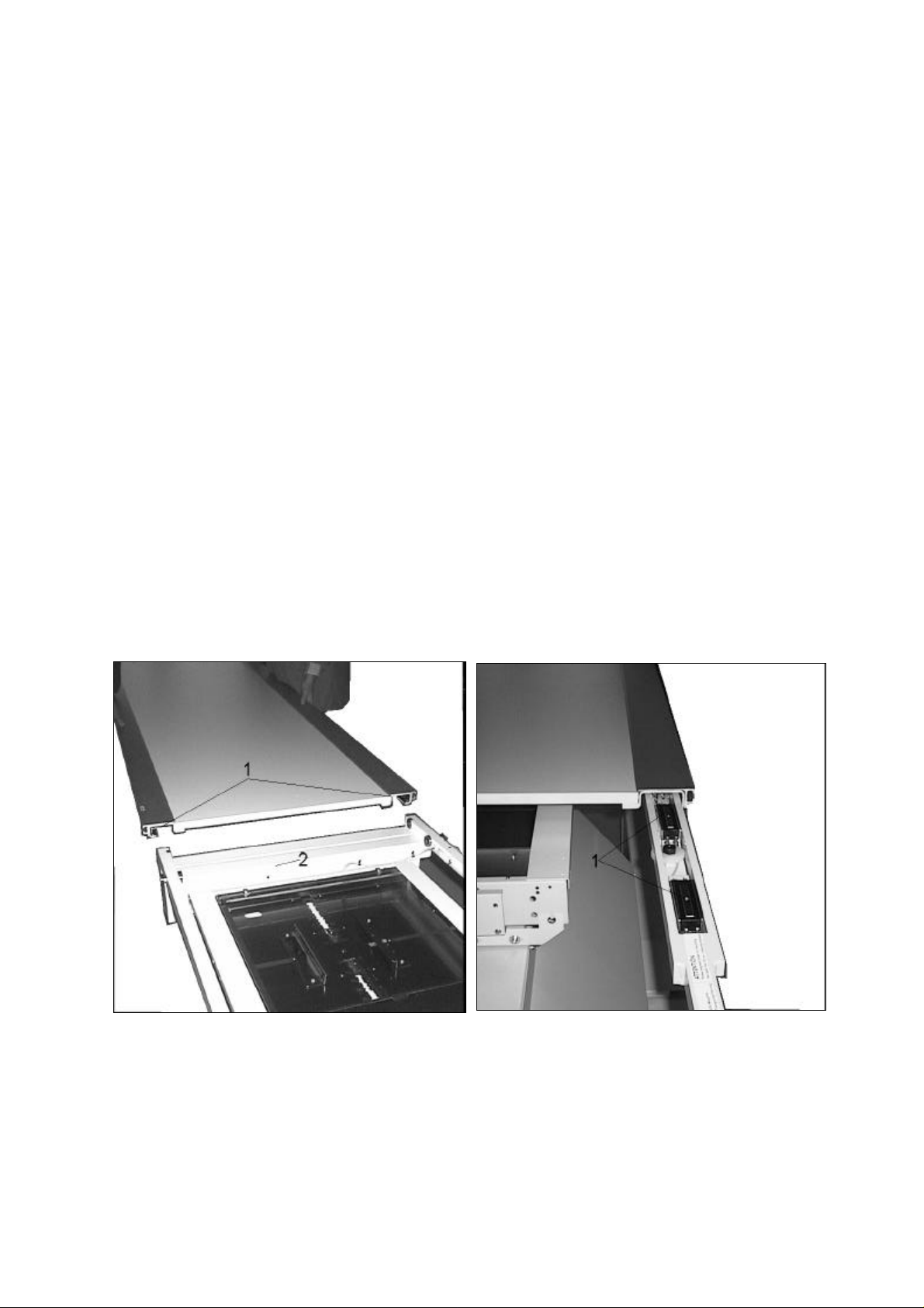
Insert the Bucky (opening of cassette to the front) in the Bucky carriage
(Fig.14/Pos.1).
Install connection cable and detector cable according to the instructions of the
manufacturer.
Bucky P
Fastening with 2 screws each (Fig. 14/Pos. 3) left and right lateral. Put at the top the
cover angle with the longer side (Fig. 14/Pos. 4) to user- and back side and fasten
above with 3 screws each and U-washer.
Philips
Fastening with 2 screws (Fig. 14/Pos. 3) left and right lateral. Put at the top the cover
angle with the longer side (Fig. 14/Pos. 4) to user- and back side and fasten above
with 3 screws each.
Siemens
Fastening with 2 screws each (Fig. 14/Pos. 3) left and right lateral.
2.5 Assembly of the table plate
Remark:
If there are less than 2900 mm from the mid of table to a wall available, please mount
the table plate according to section 2.5.1.
Remove table plate out of packing.
Dismount on one grinding the limit stop (Fig. 18/Pos. 1) and push the table top (Fig.
15/Pos. 2) on the transverse carriage.
Fig. 15 Fig. 16
Attention: Pay attention to the brake magnets while inserting the table top.
Remount limit stops (Fig. 18/Pos. 1)
0125 7221 - 20 of 44- 08/98
Revision 02 © 1998 Hans Pausch Röntgengerätebau Graf-Zeppelin-Str. 1 D-91056 Erlangen ALL RIGHTS RESERVED Ru
Page 21
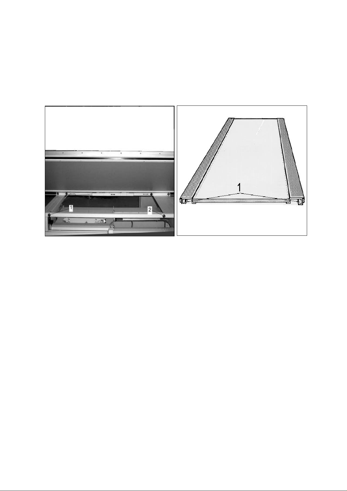
Put the included pasteboard of the table top packing on the table top during assembly
to avoid any damages.
2.5.1 Assembly of the table top in small rooms
Dismount on both grindings the limit stops Fig. 18/Pos. 1). Dismount the bearings (Fig.
17/Pos. 1 and 2) which are in the front.
.
Fig. 17 Fig. 18
Put the table top on the table frame and lift the table top on the user side about 45°.
Put meanwhile the table top rail from behind over the Polyamid roll and bearings.
Lower the table top carefully. Move the table top longitudinal and remount the
dismounted bearings. Readjust the regulations of the eccentric. Remount the limit
stops (Fig. 18/Pos. 1).
Put the included pasteboard of the table top packing on the table top during assembly
to avoid any damages.
2.6 Assembly of the tube and collimator
Siemens
Dismount the intermediate ring (Fig. 19/Pos. 59). Mount the window flange (Pos. 58)
between the adjusted flange at the factory (Fig. 19/Pos. 57) and mount to the tube
housing.
Collimat
Dismount the intermediate ring (Fig. 20/Pos. 1) out of the collimator (Pos. 2). Mount
the window flange (Fig. 20/Pos. 3) with the control arm to the tube housing. Put the
collimator (Pos. 4) onto the intermediate ring (Pos. 5) and fasten with fixing plates.
08/98 - 21 of 44- 0125 7221
Revision 02 © 1998 Hans Pausch Röntgengerätebau Graf-Zeppelin-Str. 1 D-91056 Erlangen ALL RIGHTS RESERVED Ru
Page 22
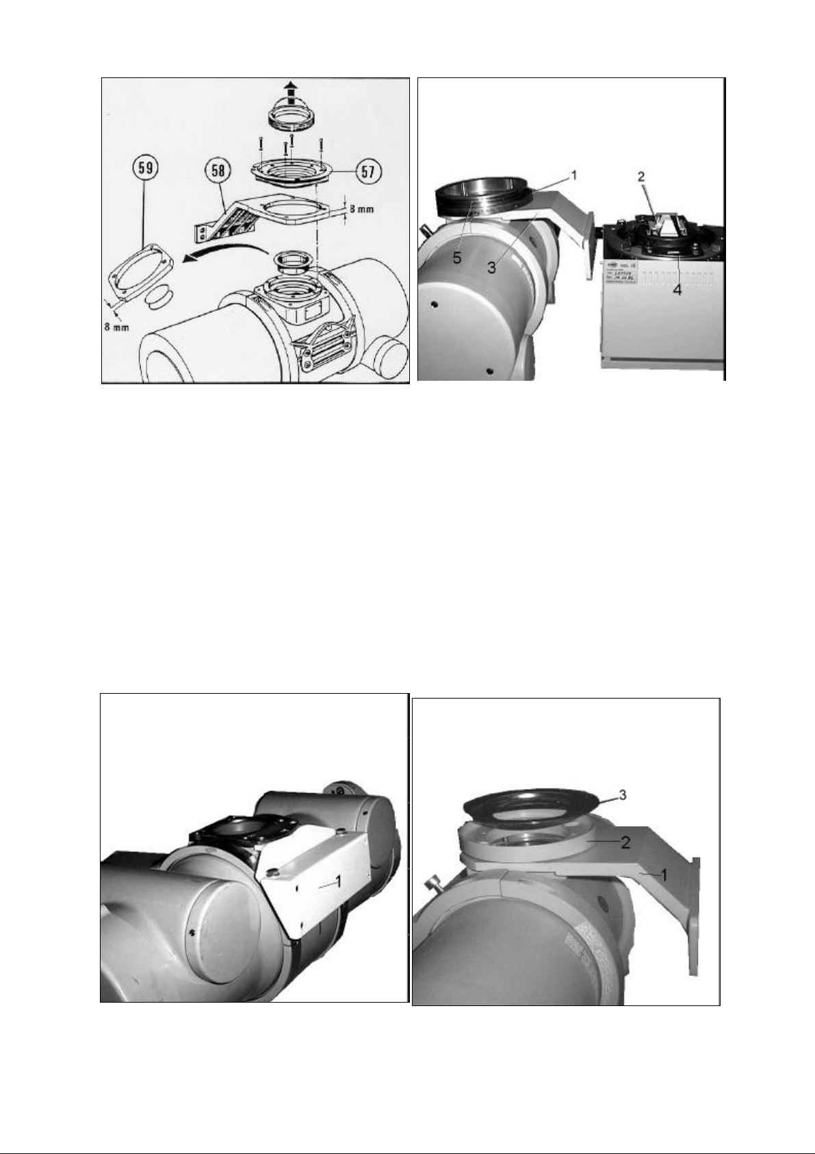
Fig. 19 Fig. 20
Philips
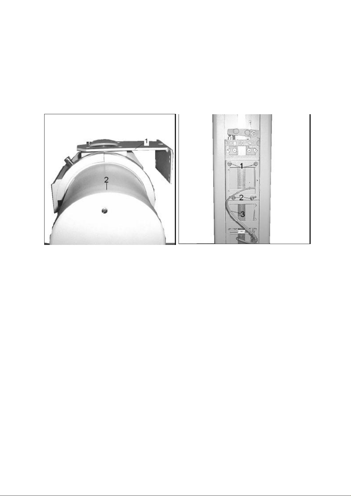
Mount the control arm with the Z-angle (Fig. 21/Pos. 1) to the Rotalix.
Other manufacturer
Fasten the control arm (Fig. 22/Pos. 1) with the window flange (Pos. 3) onto the tube
housing and mount the collimator.
USA version
Mount the control arm (Fig. 22/Pos. 1) with the support angle (Pos. 2) between tube
housing and collimator.
Fig. 21 Fig. 22
0125 7221 - 22 of 44- 08/98
Revision 02 © 1998 Hans Pausch Röntgengerätebau Graf-Zeppelin-Str. 1 D-91056 Erlangen ALL RIGHTS RESERVED Ru
Page 23
2.7 Assembly of the tube holding support
Remove the above screws (Fig. 23/Pos. 1) and loosen the lower screws (Pos. 2)
approx. 10 mm. Remove the cover of the tube holding support (Fig. 25/Pos. 1).
Put the tube holding support to the carriage support and insert the cable for the SID
switch (Fig. 24/Pos. 3) in the tube holding support. Put in over the lower screws and
fasten with the upper screws (Fig. 24/Pos. 1) the tube holding support to the vertical
carriage.
Fig. 23 Fig. 24
Fasten the lower screws (Fig. 24/Pos. 4). Lift the tube holding support slightly, then
push on safety brake (Fig. 26/Pos. 1) and lower the tube holding support slowly.
Tighten the rope and the tube holding support is suspended to the rope. Install cable
for SID switch in support arm.
2.8 Assembly of the tube on tube holding support
Move the gravity centre of the tube/collimator/control board unit into the rotation axis
by displacing the unit vertically (in direction of x-rays) on the compensating plate (Fig.
25/Pos. 1). Insert spacer plate (Pos. 2) if necessary.
08/98 - 23 of 44- 0125 7221
Revision 02 © 1998 Hans Pausch Röntgengerätebau Graf-Zeppelin-Str. 1 D-91056 Erlangen ALL RIGHTS RESERVED Ru
Page 24
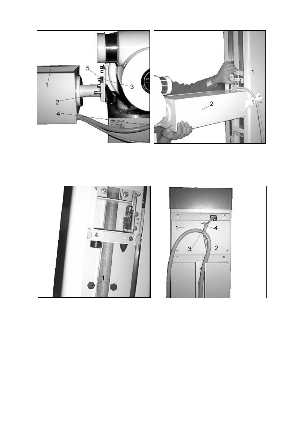
Fig. 25 Fig. 26
Note: The compensating plate must in any case be installed as distance plate, even if
the centre of gravity lies in the rotation axis.
Fig. 27 Fig. 28
Remove transport security screws (Fig. 27/Pos. 1) and insert in the head part the nuts
(Fig. 31 /Pos. 1).
2.9 Assembly of the control arm
Dismount the cover (Fig. 30/Pos. 1) on the control arm (Pos. 2). Remove the 4 screws
(Pos. 3) and mount the cover onto the control arm fastening. Cut in the cable (Fig.
25/Pos. 3) into the control arm and bring it to the cover. Then fasten with the 4 screws
(Pos. 3).
0125 7221 - 24 of 44- 08/98
Revision 02 © 1998 Hans Pausch Röntgengerätebau Graf-Zeppelin-Str. 1 D-91056 Erlangen ALL RIGHTS RESERVED Ru
Page 25
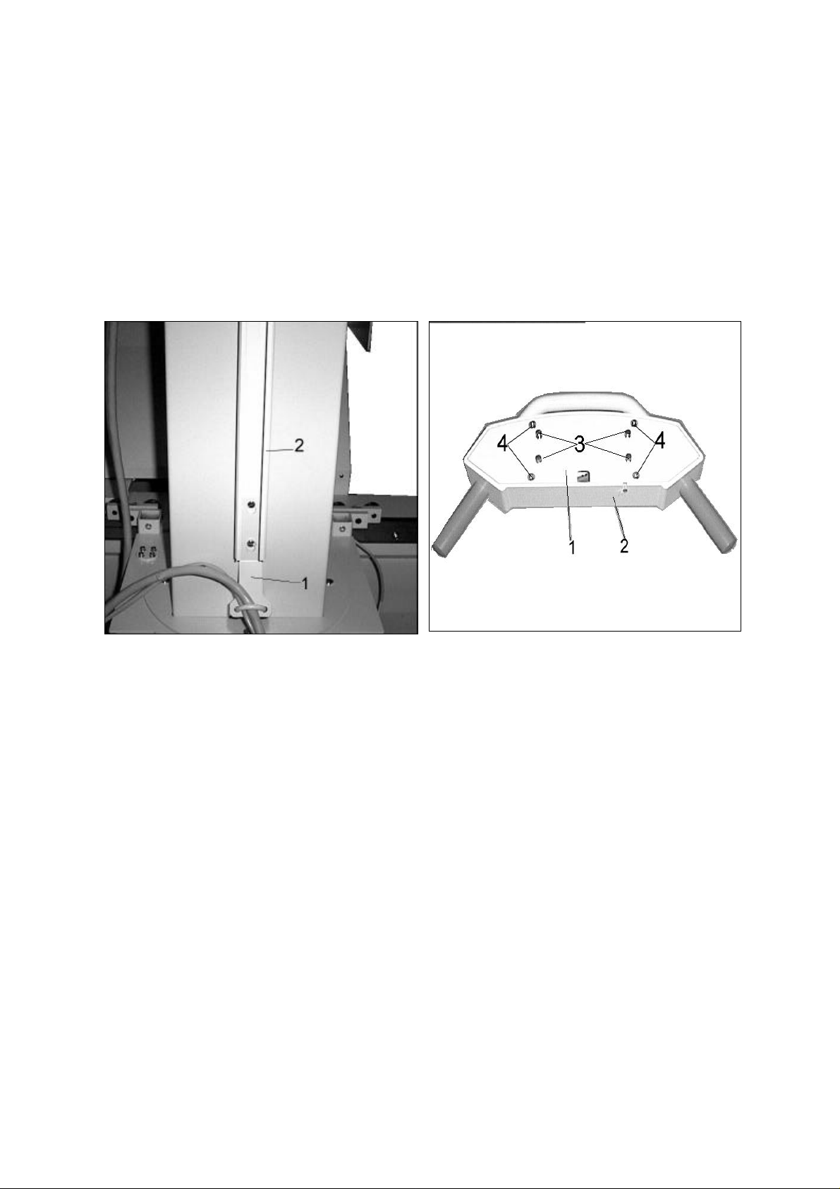
2.10 Assembly and installation of the cable
Mount the cable box (Fig. 28/Pos. 1) to the head of the column. Remove the cover of
the cable tunnel.
Insert the cable in the cable tunnel (Pos. 2) on the backside of the column. Screw
down the cable collar in the cable tunnel (Fig. 29/Pos. 1). Plug in the plugs in the
distributor plate (Fig. 12/Pos. 4). Tighten the cable to the cable box (Fig. 28/Pos. 1)
and fasten with cable binder (Pos. 2). Install cable for vertical brake and earth cord in
head part. Put cover onto the cable tunnel. Install the high-voltage cable to the tube.
Place cable over the cable collar of the vertical carriage to the cable box on the
backside of the column.
Fig. 29 Fig. 30
Leave enough running noose to the wall terminal box or ceiling terminal box (option).
Place the cables further to the x-ray generator and install according to the installation
plan of the x-ray generator.
2.11 Counterweight on the column
The tube holding support has to be counterbalanced with the installed cables. Loosen
brake and check the counterweight.
If there is a ascending force of the tube holding support remove weight plates out of
the counterbalance box.
If there is a descending force of the tube holding support put in weight plates in the
counterbalance box.
Note:
Determine the weight difference with the spring balance. Drive column beside table
and pull the tube holding support to the bottom. Secure counterbalance box with the
security screw Fig. 28/Pos. 1). Lift the tube holding support (Fig. 26/Pos. 2) some
cms. The tube holding support is suspended in the falling brake and the robe is not
fixed.
08/98 - 25 of 44- 0125 7221
Revision 02 © 1998 Hans Pausch Röntgengerätebau Graf-Zeppelin-Str. 1 D-91056 Erlangen ALL RIGHTS RESERVED Ru
Page 26
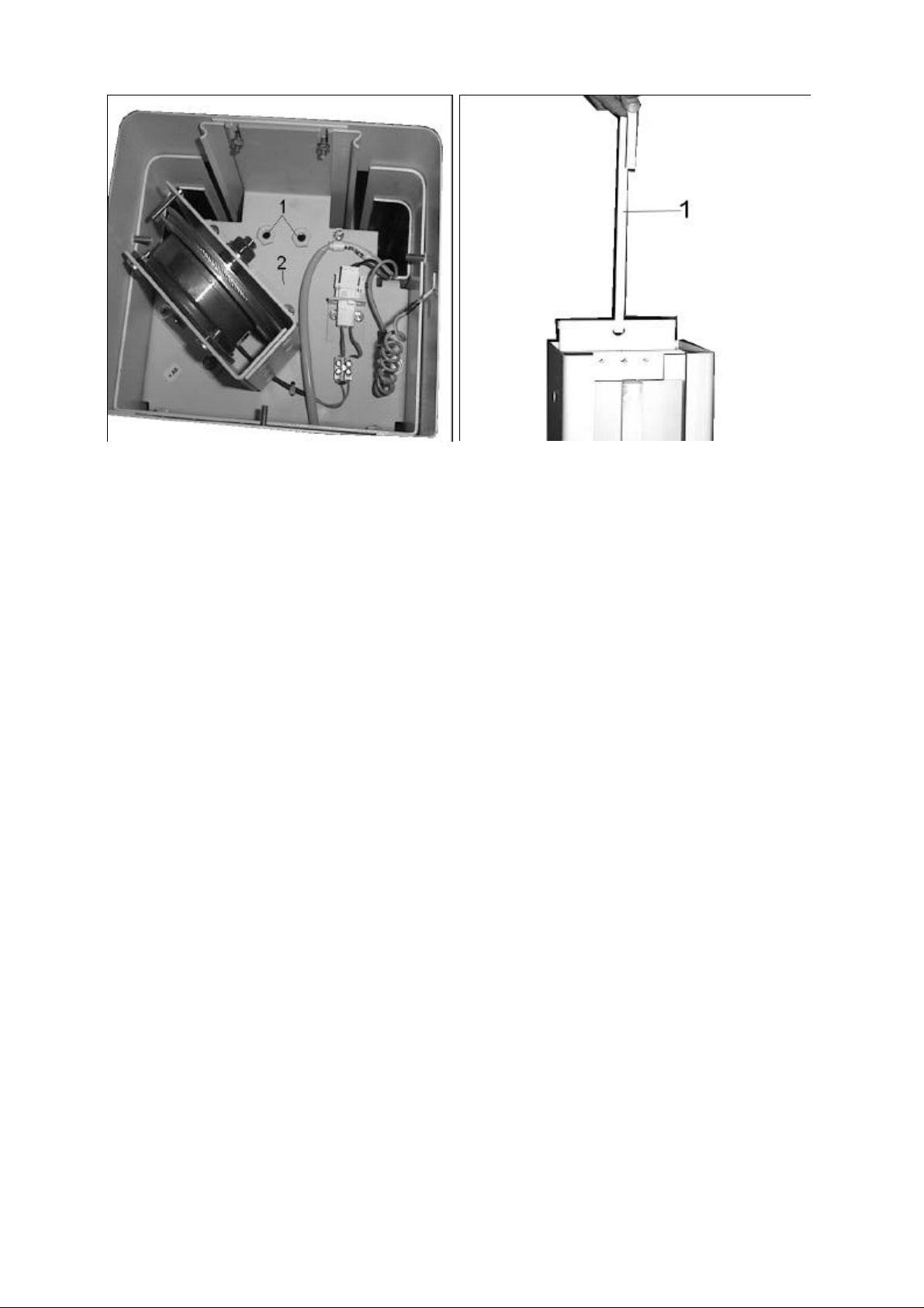
Fig. 31 Fig. 32
Lift the head part (Fig. 31/Pos. 1) with the rope pulley and secure with a cord. Balance
the calculated weight difference. Remount the head part.
Push the tube holding support slightly to the falling brake (Fig. 28/Pos. 1) and lower
slowly the tube holding support.
2.12 Function control
Switch in x-ray generator and check all functions. If necessary perform corrections
according to chapter 3. Adjustment.
2.13 Assembly of covers
Mount the lower table cover (Fig. 33/Pos. 1) with both screws (Pos. 2). Put in the front
plate (Fig. 34/Pos. 1) with bracket in the gap (Fig. 33/Pos. 3). Fasten carefully with
both socket head cap screw to table frame (Fig. 34/Pos. 2). Lock both bore-holes (Fig.
34/Pos. 3) with artificial cap.
.
0125 7221 - 26 of 44- 08/98
Revision 02 © 1998 Hans Pausch Röntgengerätebau Graf-Zeppelin-Str. 1 D-91056 Erlangen ALL RIGHTS RESERVED Ru
Page 27
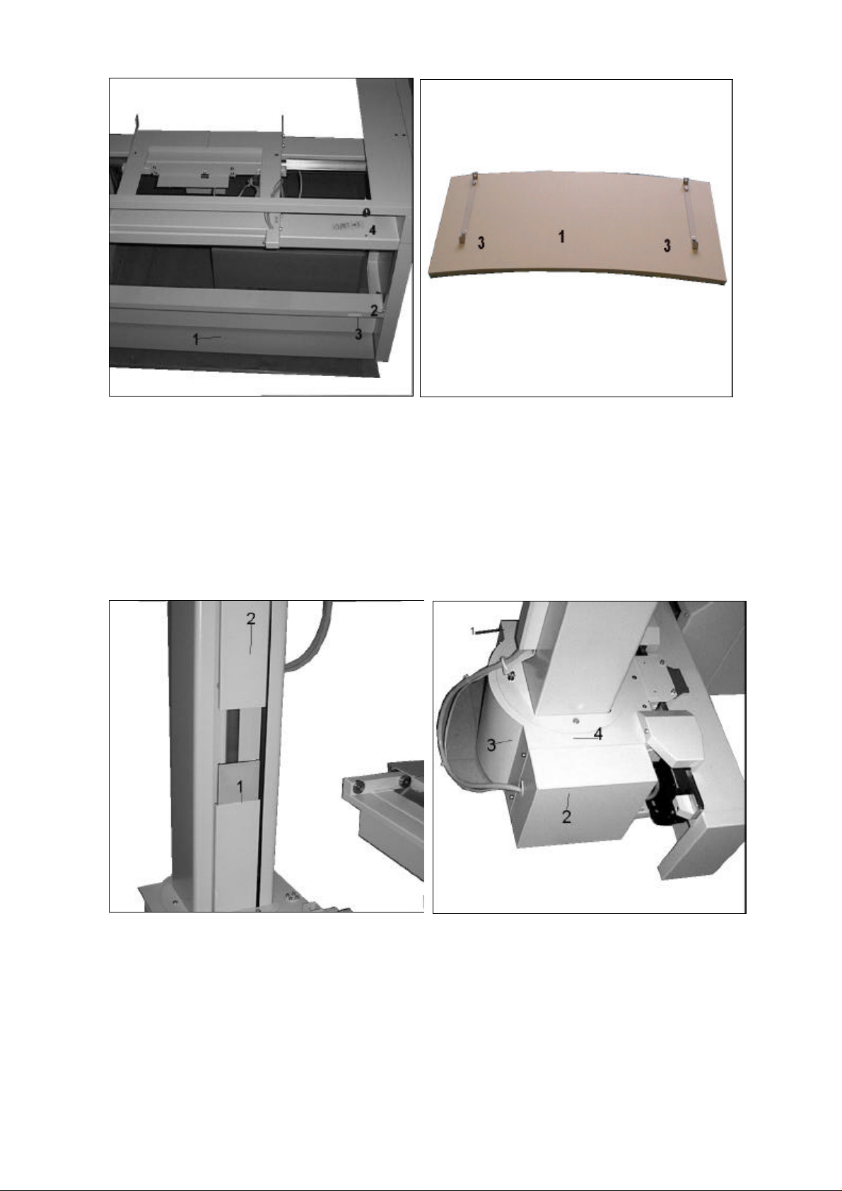
Fig. 33 Fig. 34
Drive vertical carriage to the head side and insert lower center cover (Fig. 35/Pos. 1).
Drive vertical carriage carefully down.
Attention: The lower center cover has to be carried from the coulisse. Stick the upper
center cover (Fig. 35/Pos. 2) to the lower center cover (Pos. 1). Drive the vertical
carriage to the head side and fasten the center cover with the front border (Pos. 4).
Fig. 35 Fig. 36
Mount the left cover (Fig. 36/Pos. 1), the right cover (Pos. 2) and the cap (Pos. 3) to
the column carriage (Pos. 4)
Clean equipment afterwards with a smooth cleansing agent.
08/98 - 27 of 44- 0125 7221
Revision 02 © 1998 Hans Pausch Röntgengerätebau Graf-Zeppelin-Str. 1 D-91056 Erlangen ALL RIGHTS RESERVED Ru
Page 28
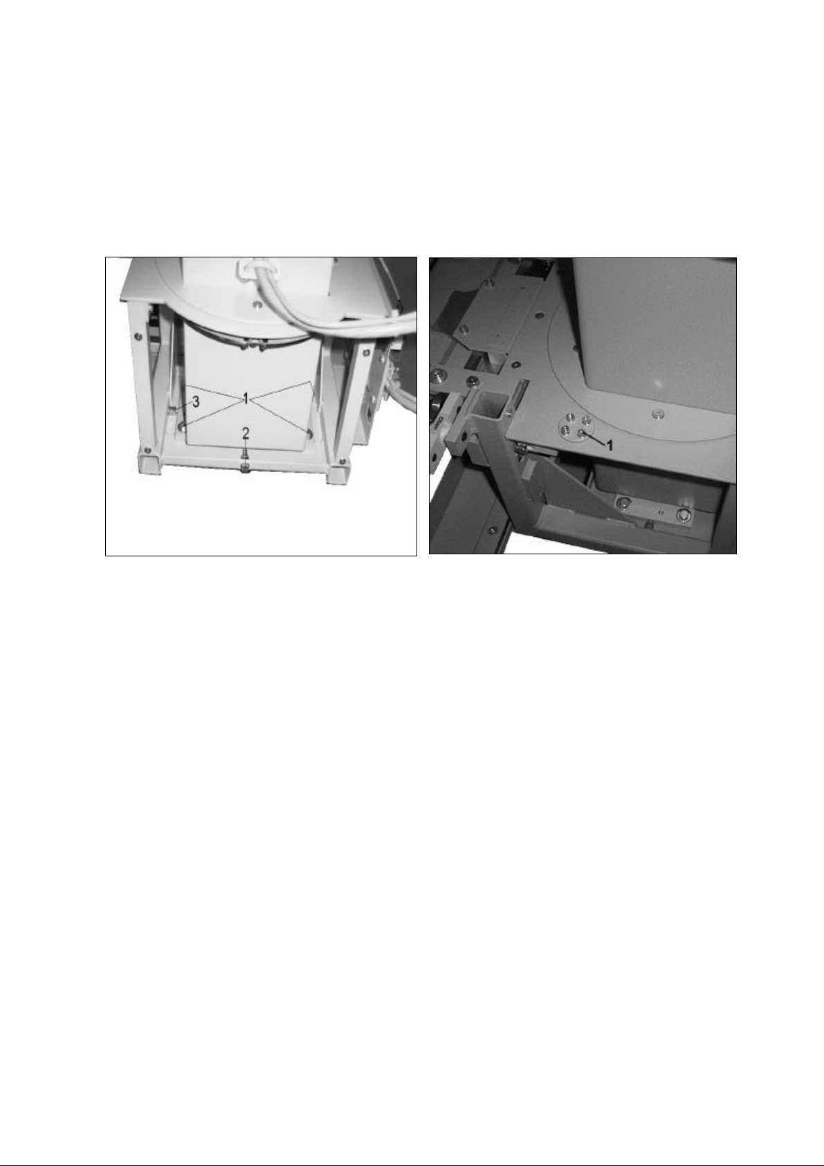
3 Adjustment
3.1 Adjustment of the column vertical
The column has been aligned constructional. If the alignment is not vertical after
assembly please align the column.
Fig. 37 Fig. 38
Remark: Remove the covering plates (Fig. 36/Pos. 1-3) from the column carriage
(Pos. 4). Loosen the 4 screws (Fig. 37/Pos. 1). Bring the column in the right position
with the corresponding adjusting screw (Pos. 2 or Pos. 3). Fasten again the 4 screws
(Pos. 1) and mount the covering plates again.
3.2 Adjustment of the column in direction of rotation
The tube holding support has been aligned constructional. If the alignment is not
correct after assembly please align.
Remark:
Loosen the 4 screws (Fig. 38/Pos. 1) slightly. Adjust the column in the corresponding
direction. Fasten the 4 screws afterwards tightly.
0125 7221 - 28 of 44- 08/98
Revision 02 © 1998 Hans Pausch Röntgengerätebau Graf-Zeppelin-Str. 1 D-91056 Erlangen ALL RIGHTS RESERVED Ru
Page 29
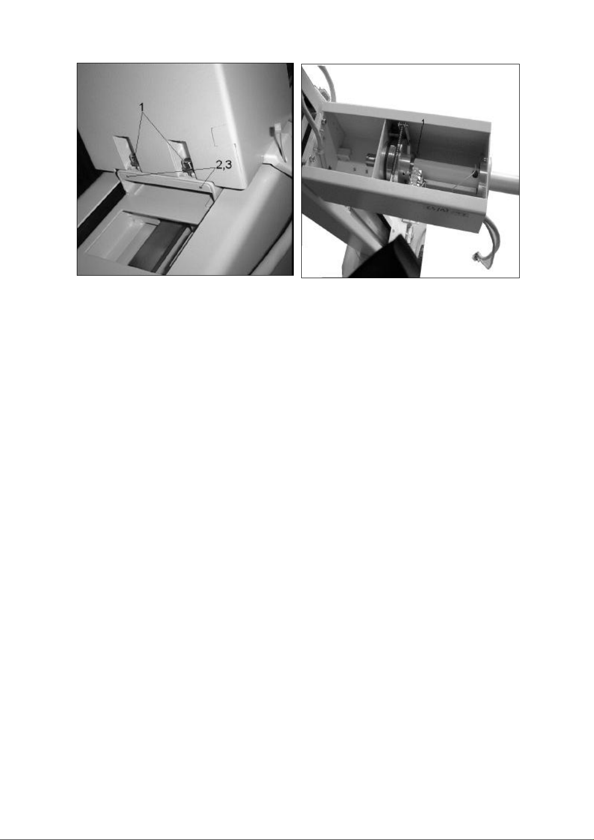
Fig. 39 Fig. 40
3.3 Adjustment of the rotational axis respectively the supporting arm
The rotational axis has been aligned constructional. If the alignment is not correct
after assembly please align.
Remark:
Loosen both lower fastening screws (Fig. 39/Pos. 1) with the shortened 6mm socket
head cap key and both security screws (Fig. 39/Pos. 2). Perform adjustment with both
adjustment screws (Fig. 39/Pos. 3) and the shortened 4 mm socket head cap key.
Fasten afterwards the fastening screws and security screws.
3.4 Adjustment of the rotation detent (0° , 90 °)
The rotational axis has been aligned constructional. If the alignment is not correct
after assembly please align.
Remark:
Loosen the nut (Fig. 40/Pos. 1) from catch. Adjust the X-ray tube assembly and fasten
afterwards the nut.
3.5 Adjustment of the Bucky in table transverse direction
Loosen the screws (Fig. 41/ Pos. 1) from the four fastening strips. Adjust the Bucky
transversely and fasten afterwards the four screws again.
08/98 - 29 of 44- 0125 7221
Revision 02 © 1998 Hans Pausch Röntgengerätebau Graf-Zeppelin-Str. 1 D-91056 Erlangen ALL RIGHTS RESERVED Ru
Page 30
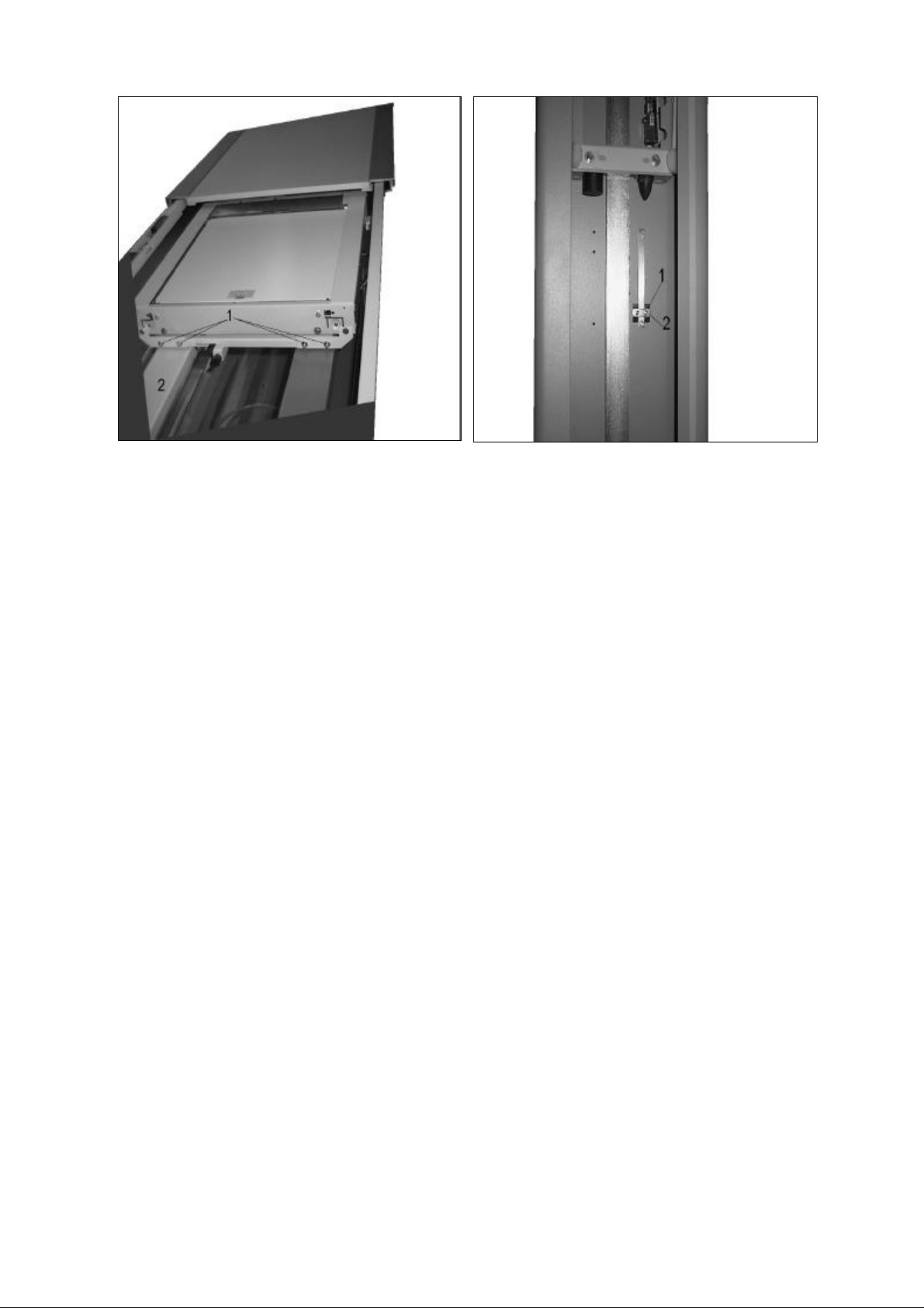
Fig. 41 Fig. 42
3.6 Adjustment of the vertical FFA switch
Loosen and displace the trip cam (Fig. 42/Pos. 1) with both screws (Pos. 2). If
necessary transpose the rail by one hole division. Tighten all screw again.
0125 7221 - 30 of 44- 08/98
Revision 02 © 1998 Hans Pausch Röntgengerätebau Graf-Zeppelin-Str. 1 D-91056 Erlangen ALL RIGHTS RESERVED Ru
Page 31
4 Technical Maintenance
4.1 Mechanical and electrical tests
The maintenance schedule described below is to be accomplished at 12-month intervals. If
functional tests require power, switch off power immediately afterwards.
Defective parts must be replaced by genuine spare parts according to spare part lists. Use
only non-acid grease for maintenance. Do not grease or oil ball bearings with sealing
washers.
Preliminary work: Check column of damages or missing parts.
Check all cables upon damage especially on the fastening points.
If necessary replace or repair as far as possible after consultation with
the customer.
Check cable loop of sufficient length.
Check all covers. If necessary replace damaged parts respectively
arrange exchange.
Check range of equipment movements on blocked objects. When
collision danger appears inform the user of all risks.
Tools: Usual assembly tools, standing ladder, torque balance key, air level,
spring balance, feeler, cleansing agent, grease, wooden lath.....cm lg.,
Preparations: Switch off equipment
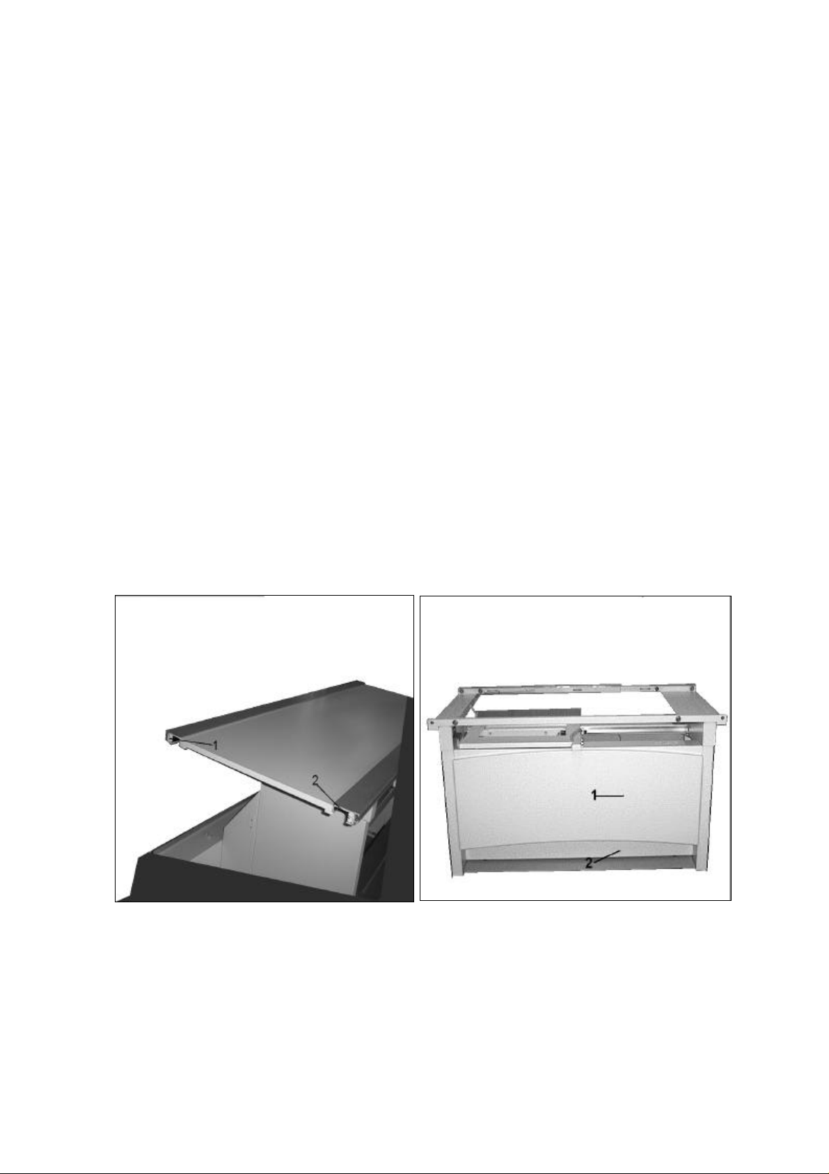
Dismount bumper and stop (Fig.45/Pos. 1+2) at either end of the table
top from profile rail (lateral).
Fig. 45 Fig. 46
Take out table top and lay aside securely.
Dismount front cover (Fig. 46/Pos. 1+2).
Remove cover left and right (Fig. 47/Pos. 1).
Dismount front border and center cover (Fig. 48/Pos. 1).
08/98 - 31 of 44- 0125 7221
Revision 02 © 1998 Hans Pausch Röntgengerätebau Graf-Zeppelin-Str. 1 D-91056 Erlangen ALL RIGHTS RESERVED Ru
Page 32
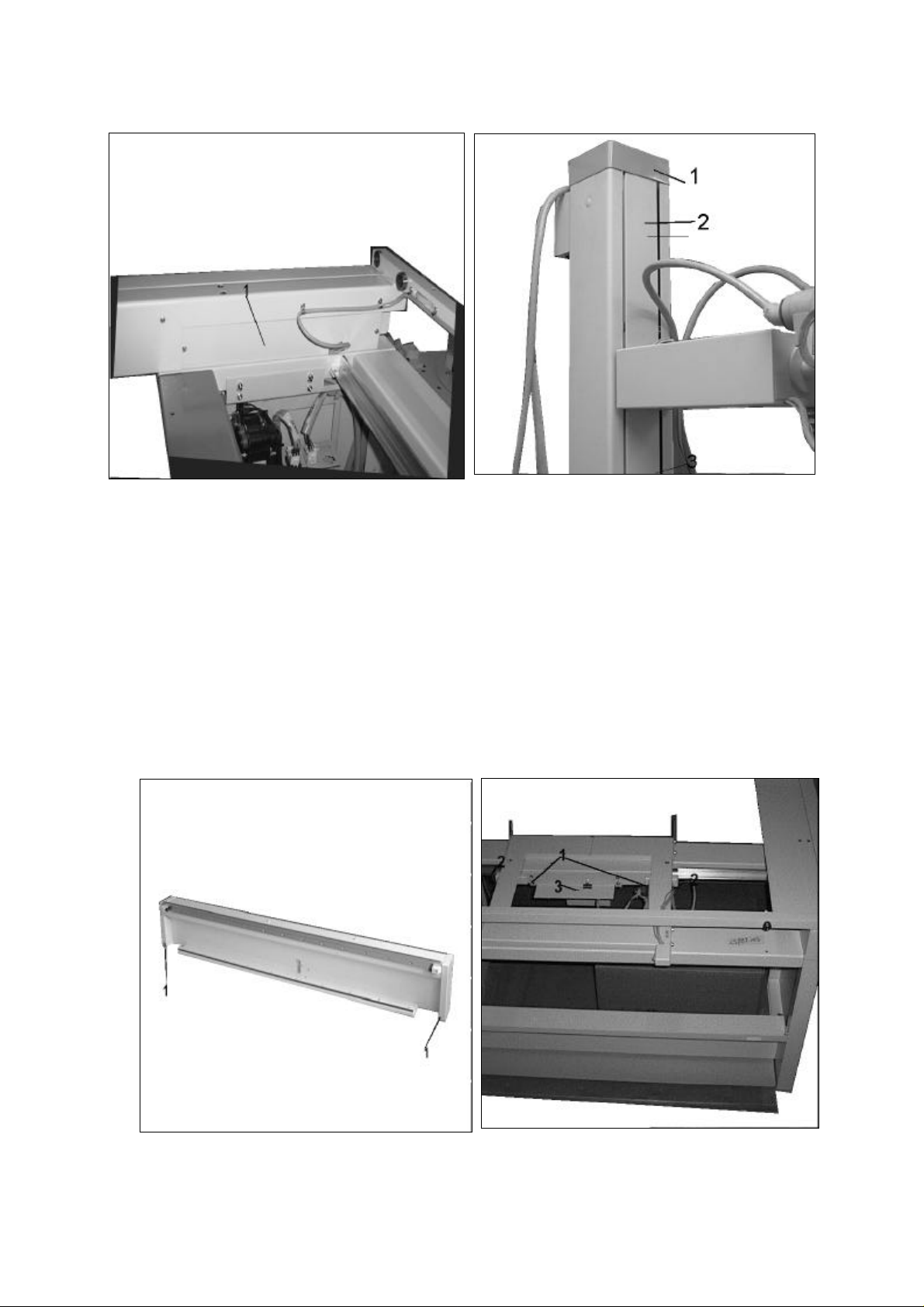
Dismount cover cap (Fig. 49/Pos. 1) on the left and right side of the rail
stand.
Fig. 47 Fig. 48
Floor mounting: Check firmness of dowel bolts. Tighten if loose. Torque wrench 50 Nm
(5.0 mkp).
Bucky carriage: Check on smooth running over total travel range. Running noise ?
Determine defective bearings. Replace if necessary.
Clean guide rail and bearings and grease lightly.
Check and if necessary adjust eccentric bearing (Fig. 50/Pos. 1).
Correct adjustment: The bearings can still be rotated by hand.
Check bumpers (Fig. 50/Pos. 2) on firmness and damage.
Switch-on equipment. Check brake (Fig. 50/Pos. 3) and adjust if
necessary.
Fig. 49 Fig. 50
0125 7221 - 32 of 44- 08/98
Revision 02 © 1998 Hans Pausch Röntgengerätebau Graf-Zeppelin-Str. 1 D-91056 Erlangen ALL RIGHTS RESERVED Ru
Page 33
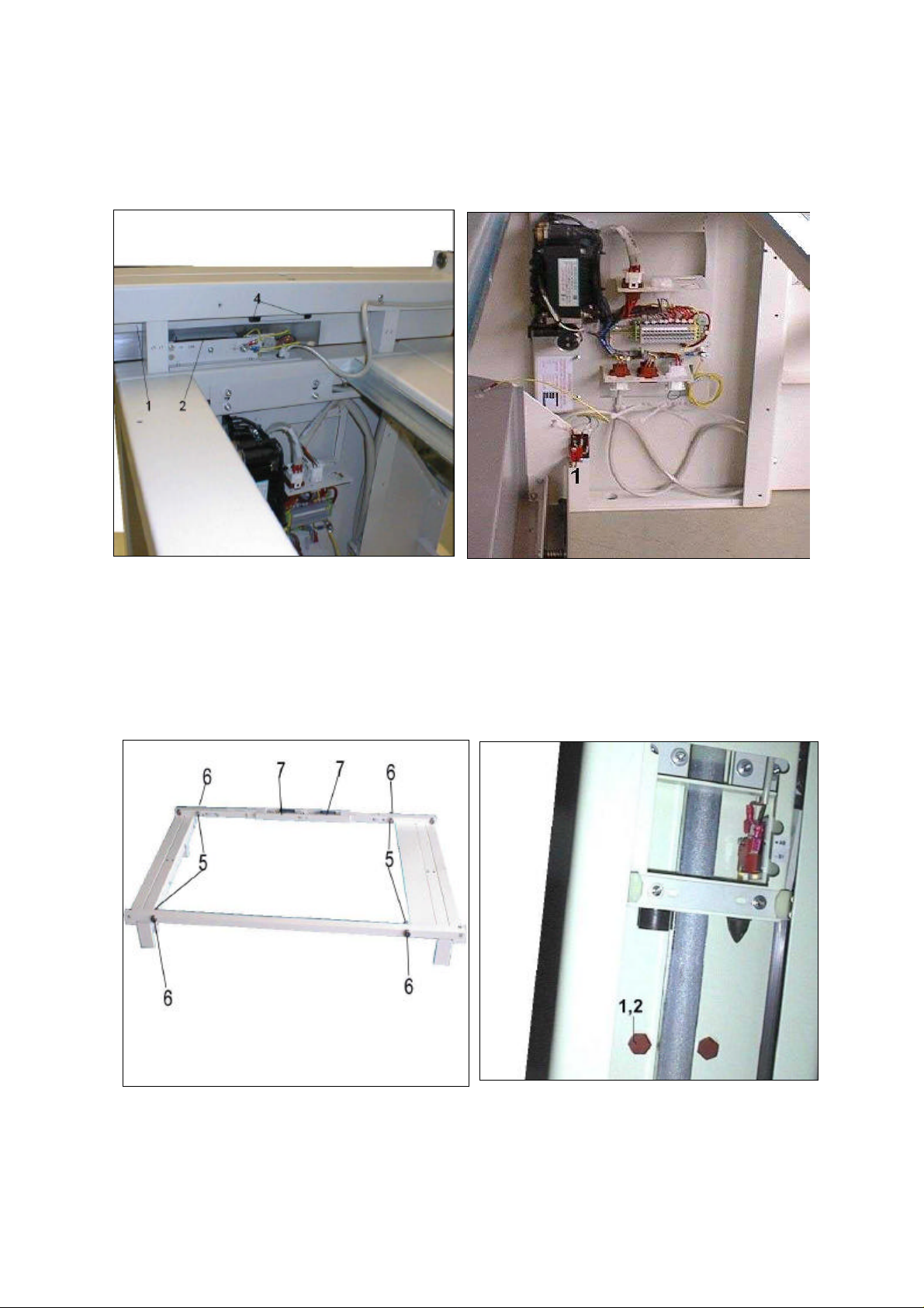
Table frame: Clean left and right guide shafts (Fig. 51/Pos. 1) and grease lightly.
Switch-on equipment. Check performance brakes for transverse
movement (Fig. 51/Pos. 2). Adjust if necessary.
Check bumpers on both sides (Fig. 51/Pos. 4) on firmness and
damage.
Fig. 51 Fig. 52
Remount the caps on the left and right side (Fig. 47/Pos. 1).
Table top: Check plastic rollers (Fig. 51/Pos. 5) for trace of wear. Replace and
grease if necessary.
Clean and check all ball bearings for table top movements on smooth
running and damage. Replace and grease if necessary.
Fig. 53 Fig. 54
Clean guide profiles of the table top.
Insert table top. Move over total travel range.
Running noise ? Smooth running ? Adjust bearings with eccentric (Fig.
51/Pos. 6) if necessary.
08/98 - 33 of 44- 0125 7221
Revision 02 © 1998 Hans Pausch Röntgengerätebau Graf-Zeppelin-Str. 1 D-91056 Erlangen ALL RIGHTS RESERVED Ru
Page 34
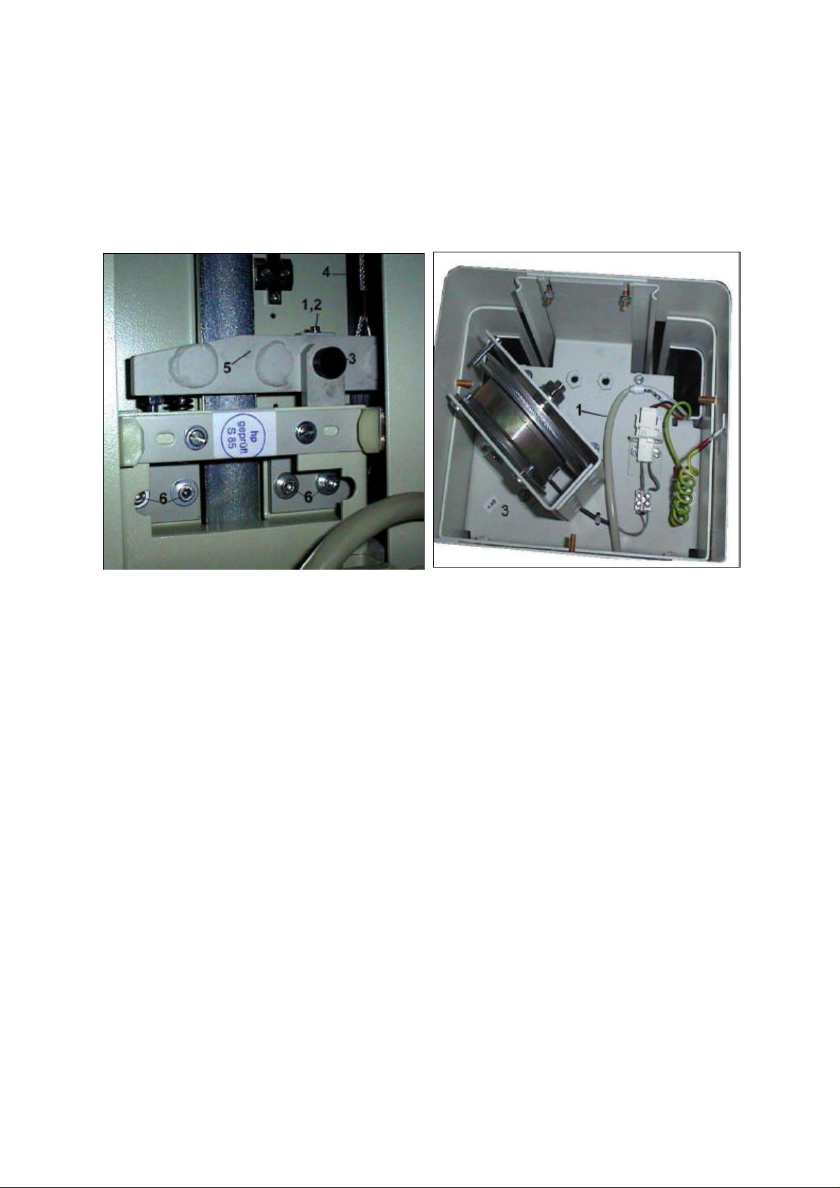
Switch on equipment. Check performance of brake (Fig. 51/Pos. 7).
Replace brake magnet if necessary .
Remount bumper and stop (Fig. 45/Pos. 1+2) at either end of the table
top to profile rail sides.
Foot Treadle: Check on smooth operation and contact point. Adjust switch (Fig.
52/Pos. 1) if necessary.
Check connections of the switches.
Grease lightly both spring axis and bearing axis.
Fig. 55 Fig. 56
Vertical carriage: Clean guide rail of the column and runners of the vertical carriage.
Check on damage and grease lightly. Check on smooth running over
entire travel range. Running noise ? Determine defective bearing.
Replace if necessary.
Check performance of safety brake.
Note: Drive vertical carriage fully down until the threaded bore-hole
(Fig. 53/Pos. 1) of the counterbalance is coincide with bore-hole in the
column. Tighten counterbalance with screws M8 (Fig. 53/Pos. 2) and c
corresponding washers. Lift vertical carriage some cms and release
only if vertical carriage is suspended to the safety brake. Lift vertical
carriage again, pull through safety brake, loosen on rope (Fig. 53/Pos.
4) to thehead side. Release slowly vertical carriage. Dismount screws
(Fig. 55/Pos. 2).
Clean steel rope (do not use fat solvents) and check upon damage.
Check on smooth running over entire travel range. At the slightest sign
of damage - (if there are 12 or more broken single lodes of the rope up
to 100 mm or 3 and more single lodes up to 10 mm or a single lode
broken) - inform the user directly. Further use of the equipment could
endanger the security of patient and user. Do not use the equipment
until the defective rope has been replaced.
Attention: The exchange of the rope has to be done at least every 3 years
Note: Drive vertical carriage fully down until the threaded bore-hole
(Fig. 53/Pos. 1) of the counterbalance is coincide with bore-hole in the
column. Tighten counterbalance with screws M8 (Fig. 53/Pos. 2) and
corresponding washers. Lift vertical carriage approx. 30 cms and
0125 7221 - 34 of 44- 08/98
Revision 02 © 1998 Hans Pausch Röntgengerätebau Graf-Zeppelin-Str. 1 D-91056 Erlangen ALL RIGHTS RESERVED Ru
Page 35
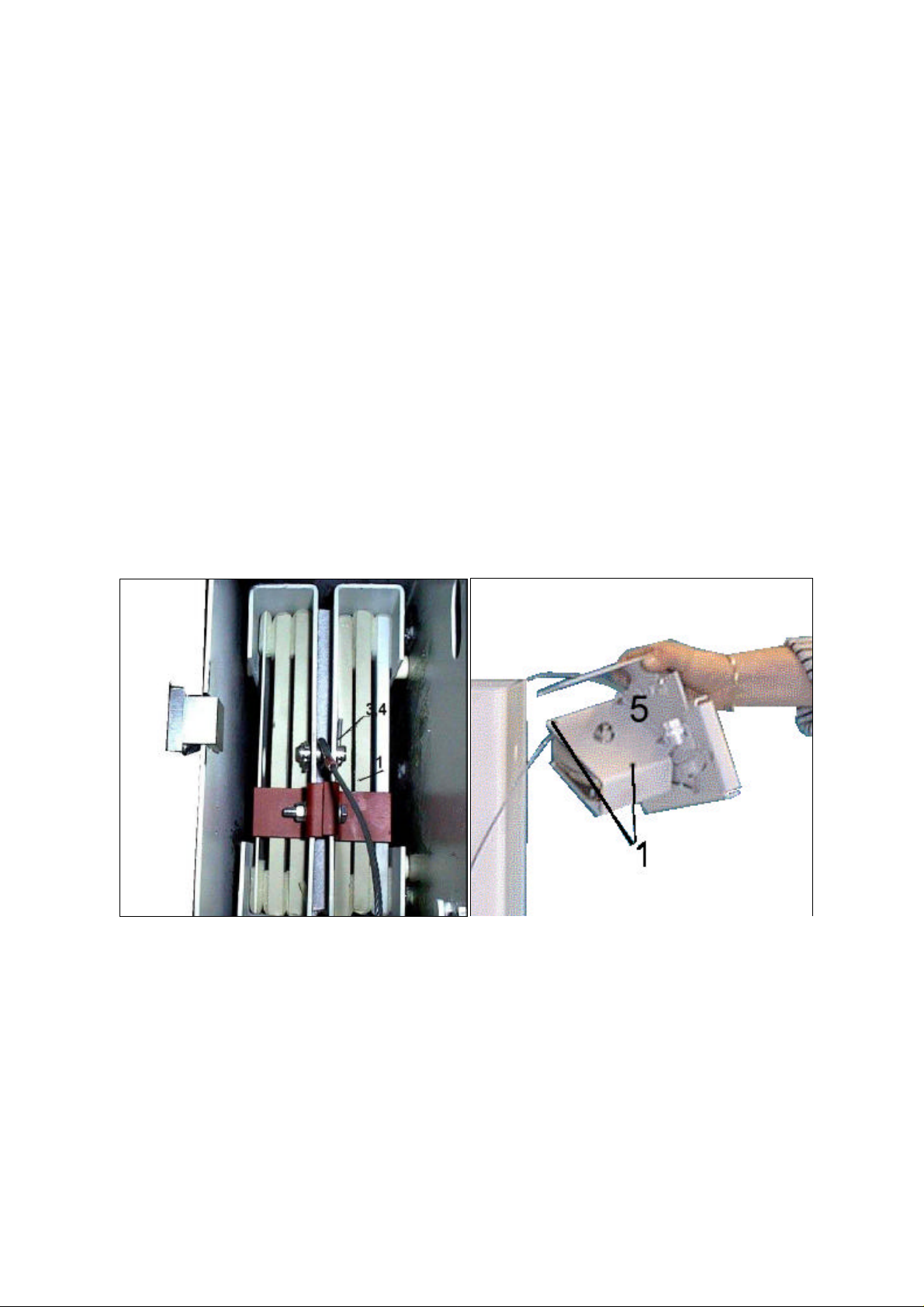
release only if vertical carriage is suspended to the safety brake. Lift
head part (Fig. 54/Pos. 1) to the top and tighten with a cord to the
column. Dismount steel rope of the counterbalance (Fig. 55/Pos. 1)
after careful removal of the security washers (Fig. 55/Pos. 3) and bolts
(Pos. 4). Support vertical carriage with the wooden lath. Remove
screws (Fig. 56/Pos. 1) and security plate (Pos. 2). Release the lever of
the safety brake (Fig. 4) in direction of the compression spring and pull
out to the front the bolt (Pos. 3). Release rope from the safety brake.
Remove from the head part the safety ring with safety nippers and
dismount rope after removal of both security screws (Fig. 56/Pos. 1).
Insert new rope in the head part and fasten to safety brake and
counterbalance. Insert again the head part, pay attention to correct
fitting. Remount lever of the safety brake to vertical carriage. Lift again
the vertical carriage slightly while pulling through safety brake of the
rope to the frontal side respectively releasing while pushing the safety
brake against the compression spring. Then let off vertical carriage
slowly. Dismount screws (Fig. 53/Pos. 2).
Check bearing play of the runners.
Note: Put a paper strip (thickness of 0,1 mm) between guide surface
and opposite bearing. If necessary press the opposite bearing with a
screw turner after removal of the screw (Fig. 57/Pos. 1) and tighten the
screw again.
Remark: The opposite bearings must be rotatable by hand over the
entire travel range.
Fig. 57 Fig. 58
Vertical brake: Remove abrasion of the magnet brake (Fig. 56/Pos. 3). Check air gap
of the magnetic clutch with feeler (Fig./Pos.). Nominal value: 0,4 - 0,5
mm. Check brake power over the entire travel range. Should be min.
150 N. The air gap can be adjusted when adding or removing washers.
Note: Drive vertical carriage fully down until the threaded bore-hole
(Fig. 53/Pos. 1) of the counterbalance is coincide with bore-hole in the
column. Tighten counterbalance with screws M8 (Fig. 53/Pos. 2) and
corresponding washers. Lift vertical carriage approx. 30 cms and
release only if vertical carriage is suspended to the safety brake. Lift
head part (Fig. 54/Pos. 1) to the top and tighten with a cord to the
column. Dismount steel rope of the counterbalance (Fig. 55/Pos. 1)
08/98 - 35 of 44- 0125 7221
Revision 02 © 1998 Hans Pausch Röntgengerätebau Graf-Zeppelin-Str. 1 D-91056 Erlangen ALL RIGHTS RESERVED Ru
Page 36
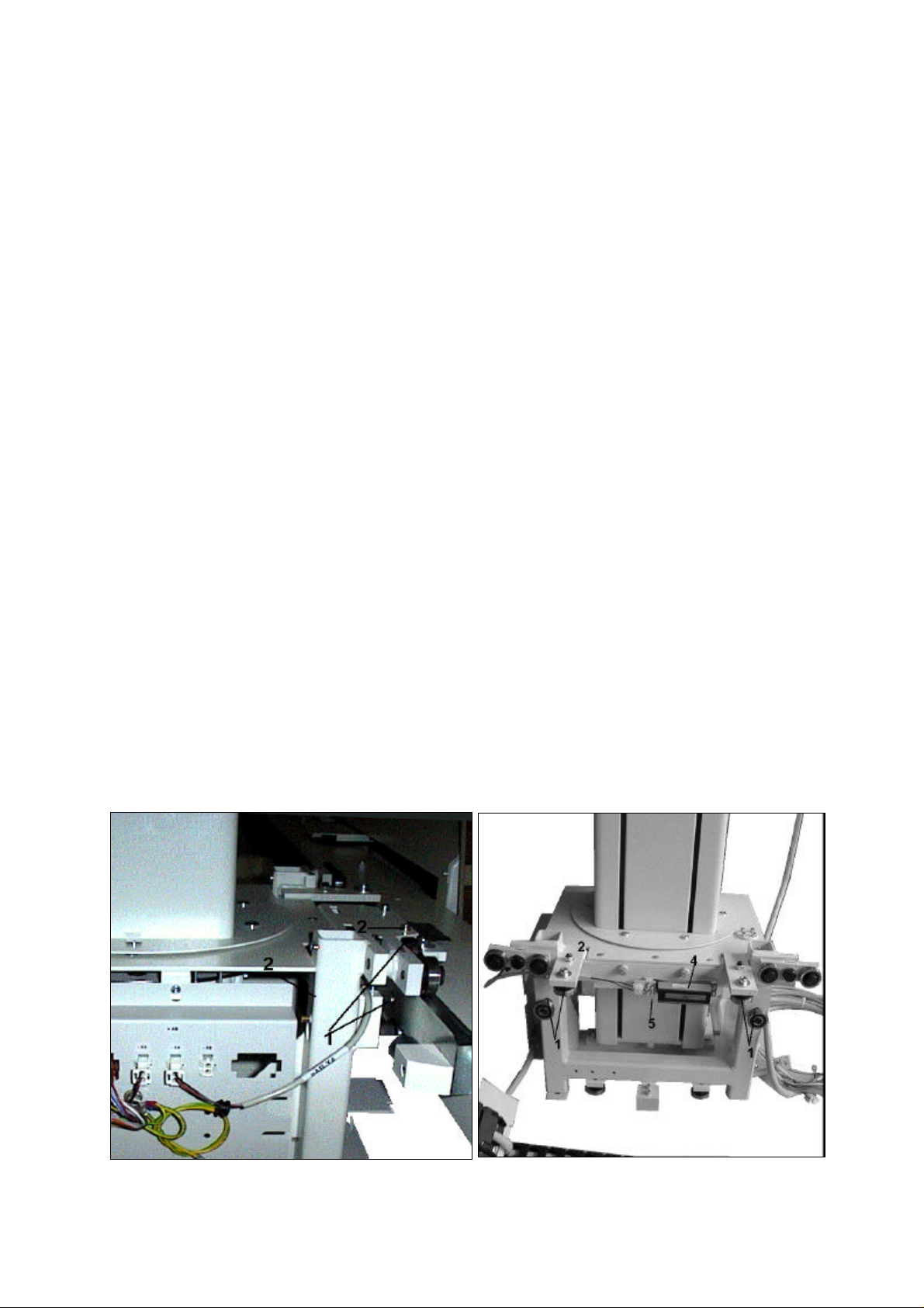
after carefully removal of the security washers (Fig. 55/Pos. 3) and
bolts (Pos. 4). Dismount steel rope after removal of both security
screws (Fig. 56/Pos. 1). Dismount guide block (Pos. 5) and adjust
difference with washers. Remount guide block. Insert head part, pay
attention to correct fitting. Lift again the vertical carriage slightly while
pulling through safety brake of the rope to the frontal side respectively
releasing while pushing the safety brake against the compression
spring. Then let off vertical carriage slowly. Dismount screws (Fig.
53/Pos. 2).
Column carriage: Clean runners of column carriage. Check upon damage and grease
slightly.
Check smooth running over entire travel range. Running noise ?
Determine defective bearing. Replace if necessary.
Check bearing play of the runners.
Note: Put a paper strip (thickness of 0,1 mm) between guide surface
and opposite bearing. If necessary press the opposite bearing with a
screw turner after removal of the screw (Fig. 58/Pos. 1) and tighten the
screw again (Fig. 58/Pos.2).
Remark: The opposite bearings must be rotatable by hand over the
entire travel range.
Switch on equipment. Check function of brake (Fig. 58/Pos. 4). Adjust if
necessary.
Note: Loosen screws (Fig. 58/Pos. 5) and displace magnet angle until
the play between brake rail and magnet is 0,2 mm. Tighten screws
again.
Rail stand: Clean upper and lower guide rail. Check on damage and grease
slightly. Check end stops on damage and check fitting. Check column
stand with air level over the entire travel range. Adjust variations while
adding spacers under or between.
Cleaning: Dirt accumulation which are not accessible for the cleaning stuff must
be removed during maintenance work.
Steep contrast agent with water and remove.
After completion of the maintenance work clean all dirt accumulations.
Fig. 59 Fig. 60
0125 7221 - 36 of 44- 08/98
Revision 02 © 1998 Hans Pausch Röntgengerätebau Graf-Zeppelin-Str. 1 D-91056 Erlangen ALL RIGHTS RESERVED Ru
Page 37
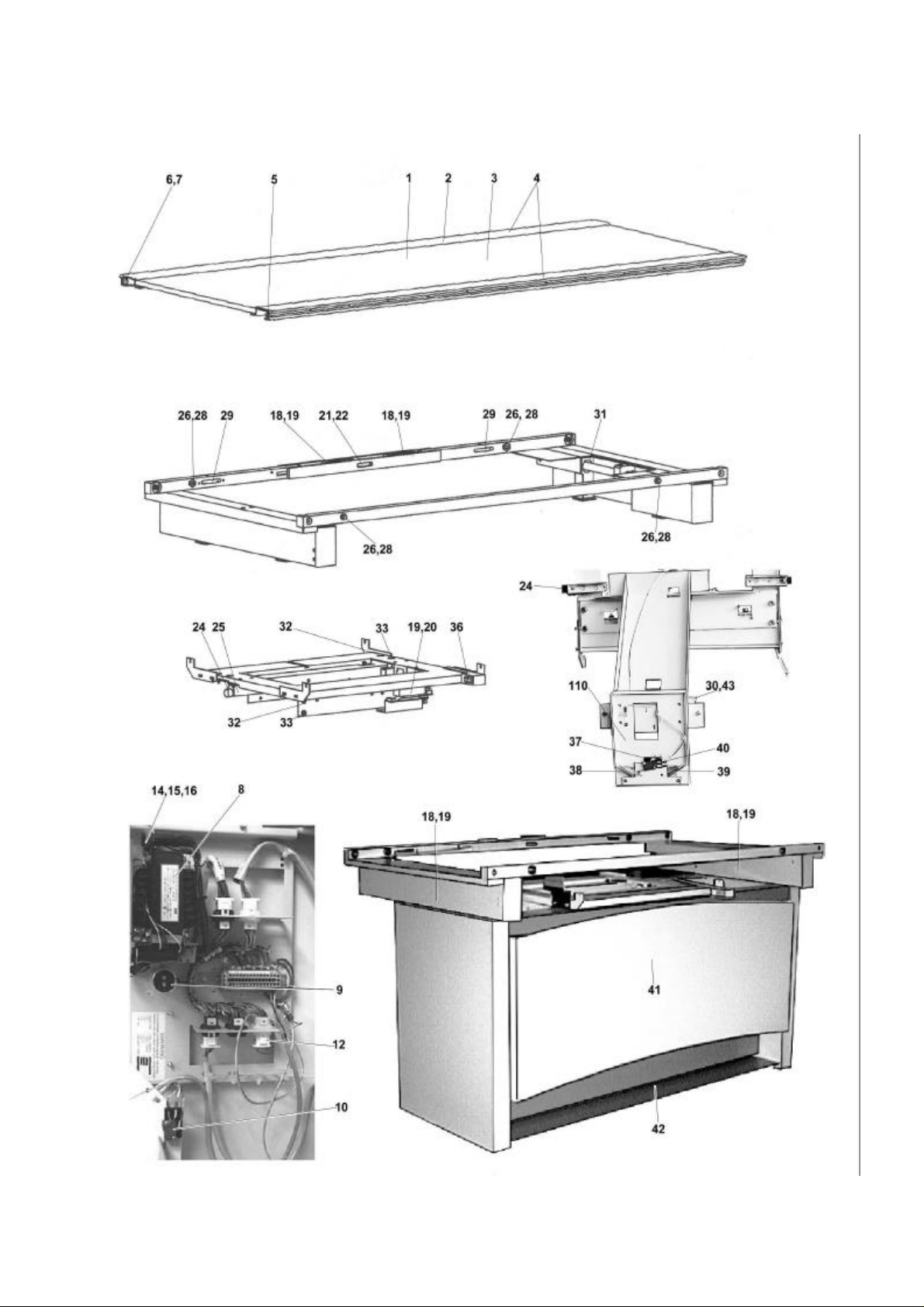
4.2 Spare Parts Table
08/98 - 37 of 44- 0125 7221
Revision 02 © 1998 Hans Pausch Röntgengerätebau Graf-Zeppelin-Str. 1 D-91056 Erlangen ALL RIGHTS RESERVED Ru
Page 38
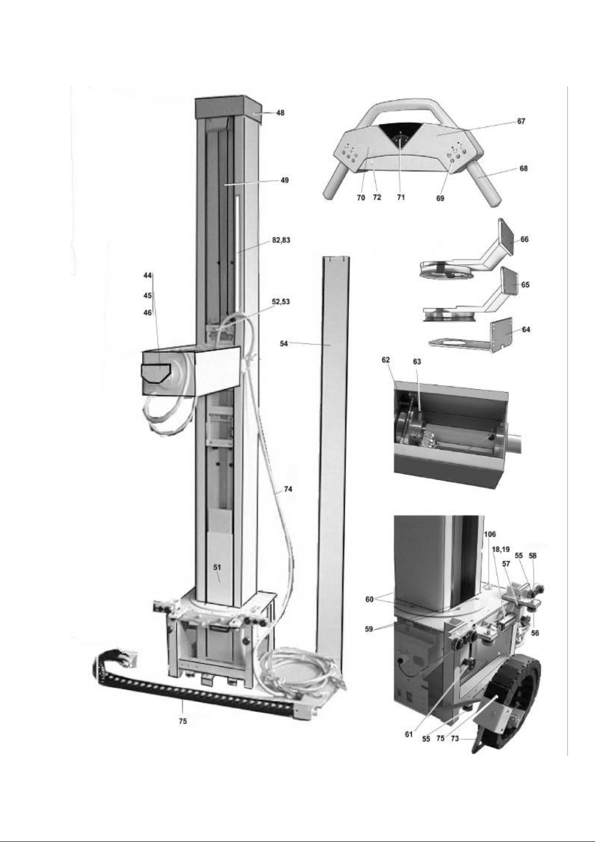
4.2.1 Spare Parts Column sheet 1
0125 7221 - 38 of 44- 08/98
Revision 02 © 1998 Hans Pausch Röntgengerätebau Graf-Zeppelin-Str. 1 D-91056 Erlangen ALL RIGHTS RESERVED Ru
Page 39
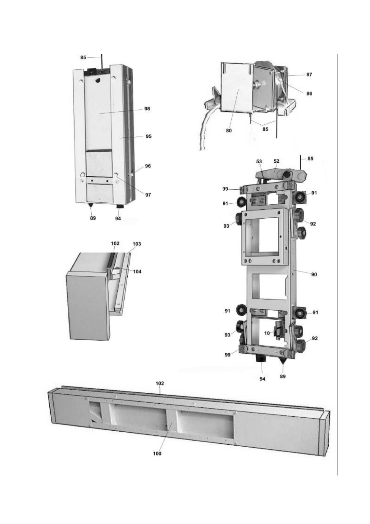
4.2.1 Spare Parts Column sheet 2
08/98 - 39 of 44- 0125 7221
Revision 02 © 1998 Hans Pausch Röntgengerätebau Graf-Zeppelin-Str. 1 D-91056 Erlangen ALL RIGHTS RESERVED Ru
Page 40

4.3 Spare Parts List
Description / Order No.
Note:
Defective parts must only be replaced by genuine spare parts as listed below. When
ordering please always specify the serial number of the unit and the full order number of the
part.
Parts or part assemblies may only be replaced by the manufacturer or parties expressly
authorised. See also chapter on „Safety Procedures“.
Pos. Description Order-No.
1 Table top complete 0622 0540a
2 Table top frame 0622 0541
3 Table top 0622 0548
4 Profile rails 0622 0549
5 Stop 0622 0550a
6 Stop 0622 0550b
7 Bumper 0005 0164g
8 Power supply 0006 0449
9 Capacitor 3110 0028
10 Switch 0006 0184
11
12 Bridge plug 0632 0306
13
14 Fuse plug 1,6A 0006 0308b
15 Fuse plug 3,2A 0006 0308g
16 Fuse plug 10A 0006 0308k
17
18 Laminated spring 0632 0418
19 Brake solenoid 0006 0603
20
21 Guide pulley 0632 0420
22 Eccentric 0632 0421
23
24 Bumper 0005 0108
25 Bumper support 0622 0620
26 Bearing with eccentric 0622 0555
27
28 Bearing with bushing 0622 0556
29 Guide pulley 0632 0422
30 Bearing 2400 0013
31 Bearing 0005 0191a
32 Eccentric axis 0632 0659
33 Bearing axis 0632 0657
36 Button 0006 0720a
37 Switch 0006 0079a
38 Catch lever 0322 0637b
39 Catch lever 0322 0637a
0125 7221 - 40 of 44- 08/98
Revision 02 © 1998 Hans Pausch Röntgengerätebau Graf-Zeppelin-Str. 1 D-91056 Erlangen ALL RIGHTS RESERVED Ru
Page 41

Pos. Description Order-No.
40 Switch lever 0006 0450
41 Trough complete 0632 0160
42 Pedal 0632 0125
43 Eccentric axis 0632 0610
44 Tube support arm 100 mm 0125 0815a
45 Tube support arm 127 mm 0125 0815b
46 Tube support arm GE 0125 0815d
47 Tube support arm Toshiba 0125 0815e
48 Head piece weld 0125 0580
49 Strip 0125 0550
50 Tube saddle 0125 0780
51 Cover bottom 0370 0138
52 Spring 0005 0159
53 Safety brake II 0125 0733
54 Cover top 0125 0570
55 Bearing with bolt 0125 0374
56 Bearing with eccentric 0125 0369a
57 Bearing with bushing 0125 0369b
58 Bolt 0125 0383
59 Bearing with bolt 0125 0376
60 Bearing with eccentric 0125 0377
61 Bearing with eccentric 0125 0373
62 Solenoid bracket 0006 0687
63 Detent quick release ass. 0125 0880
64 Control housing 0322 0629
65 Control housing 0322 0270
66 Control housing 0322 0273
67 Control handle assembly 0125 1000a
68 Handle 0125 1008
69 Button
70 Print board 0125 1020
71 Angle indicator 0125 1010
72 Table measure 0125 1019
73 Cable table 0125 1607a
74 Cable column 0125 1606
75 Timing Belt 0006 0686
76 Spring 0005 0042f
77 Pulley 0322 0118
78
79
80 Column top assembly 0125 0650
81
82 Scale cm 0008 0106
83 Scale inch 0008 0107
84
85 Wire rope 0125 0662
86 Wire rope pulley 0125 0659
87 Solenoid bracket 0323 0555
88
89 Parabolic spring 0005 0103a
08/98 - 41 of 44- 0125 7221
Revision 02 © 1998 Hans Pausch Röntgengerätebau Graf-Zeppelin-Str. 1 D-91056 Erlangen ALL RIGHTS RESERVED Ru
Page 42

Pos. Description Order-No.
90 Vertical carriage 0125 0701
91 Sole plate 0125 0725
92 Bearing balance 0125 0720a
93 Bearing balance 0125 0720b
94 Bumper 0005 0164h
95 Counterweight 0125 0601b
96 Glide block 0125 063
97 Glide block 0125 063
98 Weight plate 0125 0623
99 Profile 0370 0137
100 Rail assembly 0125 0115
101
102 Rail 0125 0202
103 Floor guide rail 0125 0136
104 Stop 0125 0137
105
106 Detent quick release ass. 0125 0340
107
108 Catch 0125 1243
109
110 Coupling assembly 0125 1210
112 Switch 0006 0184
113 Wiper 0322 0131
114 Guide for wiper 0322 0130
0125 7221 - 42 of 44- 08/98
Revision 02 © 1998 Hans Pausch Röntgengerätebau Graf-Zeppelin-Str. 1 D-91056 Erlangen ALL RIGHTS RESERVED Ru
Page 43
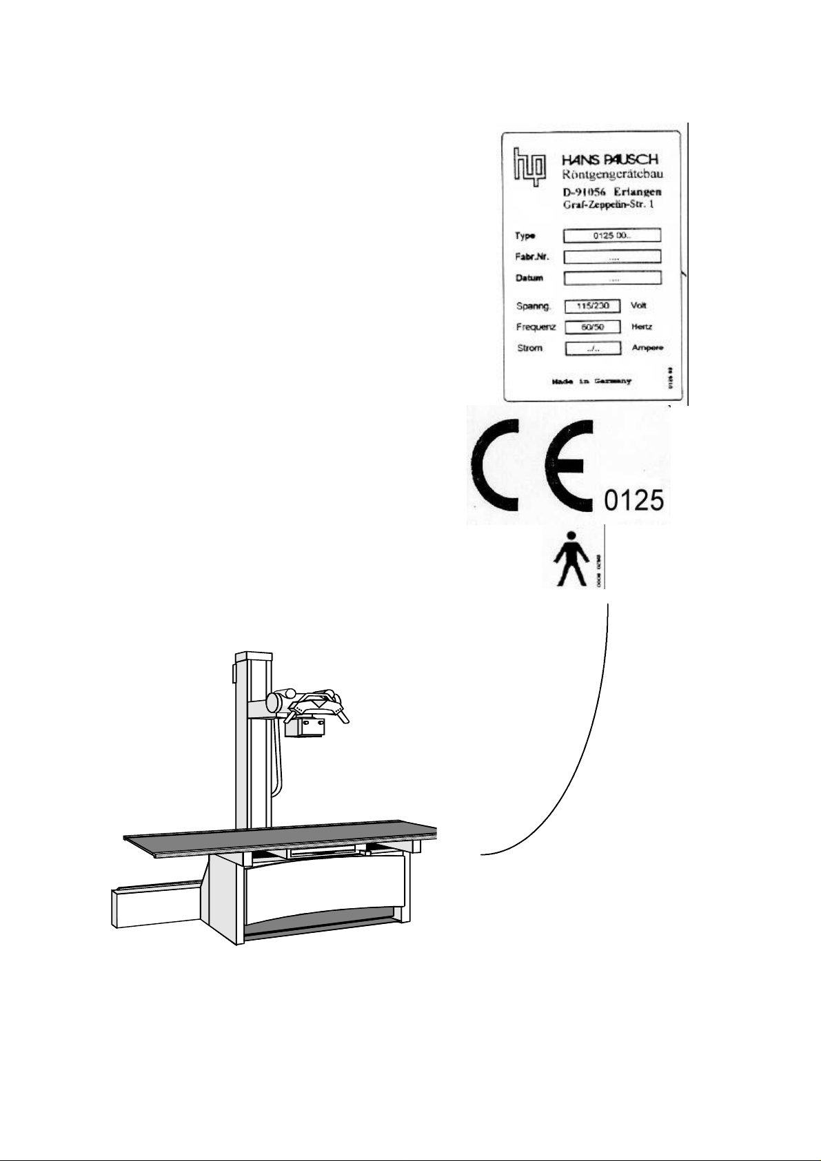
Name Plate Location:
08/98 - 43 of 44- 0125 7221
Revision 02 © 1998 Hans Pausch Röntgengerätebau Graf-Zeppelin-Str. 1 D-91056 Erlangen ALL RIGHTS RESERVED Ru
Page 44

4.5 Maintenance Certificate
The maintenance according to the attached maintenance instructions has been carried
out. Any parts replaced were original spare parts as shown on the list.
Replaced parts (List item no. only)
----------------------------------------------------------------------------------- Date Name of company Signature
Replaced parts (List item no. only)
----------------------------------------------------------------------------------- Date Name of company Signature
Replaced parts (List item no. only)
----------------------------------------------------------------------------------- Date Name of company Signature
Replaced parts (List item no. only)
---------------------------------------------------------------------------------- Date Name of company Signature
Subject to technical alterations TV/Ru
0125 7221 - 44 of 44- 08/98
Revision 02 © 1998 Hans Pausch Röntgengerätebau Graf-Zeppelin-Str. 1 D-91056 Erlangen ALL RIGHTS RESERVED Ru
 Loading...