

pauly CPV1038 01 Series, CPV1038 Operating Instructions Manual
Fotoelektrik Pauly – Light barriers
pauly
Features
Functionalities
Cat. 2, PL=c, SIL 1
in acc. with EN ISO 13849 and
EN 62061
Two optical systems in one
enclosure
Two adjustable independent
clearance distances
Clearance distance up to 50 m
High performance in terms of
detection
Pollution warning/ Anti Sabotage
system
Integrated test system – a highly
dynamic process reproduces the
light reflected by the reflector
Safe mounting of reflectors
o Collision protection
o Distance monitoring
Only for cranes that run on a common crane
track or rail.
Revision Index:
2019
-29
Revision date:
12.04.2019
Processed by:
tb
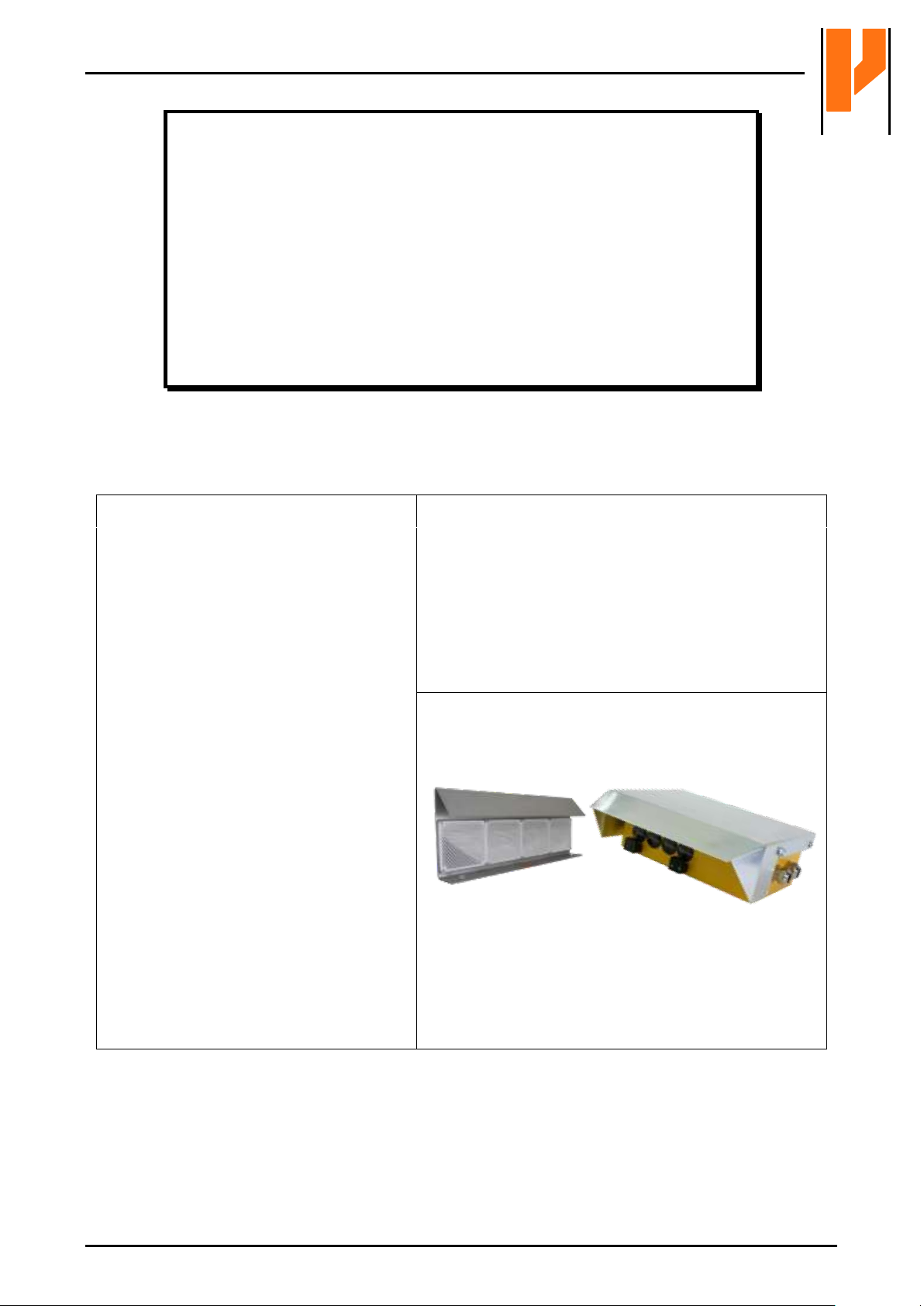
Operating instructions
Optical Anti-Collision Device
Type CPV1038
E_52692.pdf
E_52692 Ref. 2019-29 1/24
Fotoelektrik Pauly GmbH, Wahrbrink 6, D-59368 Werne, T: +49 2389/402 27-70, F: +49 2389/402 27-77
http://www.fotoelektrik-pauly.de, eMail: info@fotoelektrik-pauly.de

Fotoelektrik Pauly – Light barriers
Table of Contents
1. Identification / General Remarks 3
1.1 Product versions / Plates representations 3
1.2 Name and address of the manufacturer 3
1.3 Applied standards and technical specifications: 4
1.4 Definition of symbols: 4
2. Product description 4
2.1 Product mark 4
2.2 Intended use, general function and area of application 5
2.3 Incorrect use and foreseeable misuse 5
2.4 Safety information 6
3. Definitions – technical data 7
4. Operating instructions 9
4.1 Information on this technical description 9
4.2 Device description 9
4.3 Description of function 10
4.3.1 Triangulation triangle 10
4.3.2 Approach movement 11
4.3.3 Continually self-testing 12
4.3.4 Possible movement of the crane 12
4.3.5 Movement of the crane is stopped 12
4.4 Pollution control function 13
4.4.1 Principle 13
4.4.2 Pollution example 13
4.4.3 Pollution Indicator – meaning of the different circuit states 14
4.5 Assembly 15
4.5.1 Horizontal arrangement of the triangulation triangle 15
4.5.2 Distance monitoring accuracy 16
4.5.3 Taking the tolerances into consideration with respect to clearance distance 17
4.6 Information on assembly 18
4.7 Adjustment using the “light beam method” 19
4.8 Electrical connection 20
4.9 Applicable documents 22
5. Maintenance and cleaning 22
6. Contents of the EU Declaration of Conformity 23
7. Decommissioning 24
8. Spare parts 24
E_52692 Ref. 2019-29 2/24
Fotoelektrik Pauly GmbH, Wahrbrink 6, D-59368 Werne, T: +49 2389/402 27-70, F: +49 2389/402 27-77
http://www.fotoelektrik-pauly.de, eMail: info@fotoelektrik-pauly.de
Fotoelektrik Pauly – Light barriers
Bezeichnung
General description
Optical Anti-Collision Device
Typ
Type
CPV1038
CPV1038 /R/2M20/i/… 5269x…
0393
Seriennummer
Serial number
Baujahr
Year of manufacture
Reichweite
Range
0,5…25/50m
Versorgung
Supply
Schutzart
Protection mode
IP65
Reaktionszeit
Response time
80ms
Fotoelektrik Pauly
59368 Werne / Germany
www.fotoelektrik-pauly.de
Bescheinigungsnummer
Certificate number
HSM 09 079
Sicherheits-Integritätslevel
Safety Integrity Level
1
gemäß DIN EN 62061
according to DIN EN 62061
Sicherheitskategorie
Safety category
2
Performance
Level
c
MTTFd [a]
86
gemäß DIN EN ISO 13849-1
according to DIN EN ISO 13849 -1
Bezeichnung
General description
Optical Anti-Collision Device
Typ
Type
CPV1038*01
CPV1038*01 /R/2M20/i/… 5269M01x…
0393
Seriennummer
Serial number
Baujahr
Year of manufacture
Reichweite
Range
1…25m
Versorgung
Supply
Schutzart
Protection mode
IP65
Reaktionszeit
Response time
80ms
Fotoelektrik Pauly
59368 Werne / Germany
www.fotoelektrik-pauly.de
Bescheinigungsnummer
Certificate number
HSM 09 079
Sicherheits-Integritätslevel
Safety Integrity Level
1
gemäß DIN EN 62061
according to DIN EN 62061
Sicherheitskategorie
Safety category
2
Performance
Level
c
MTTFd [a]
86
gemäß DIN EN ISO 13849-1
according to DIN EN ISO 13849 -1
1. Identification / General Remarks
1.1 Product versions / Plates representations
CPV1038
CPV1038*01
1.2 Name and address of the manufacturer
Fotoelektrik Pauly GmbH
Wahrbrink 6
59368 Werne, Germany
E_52692 Ref. 2019-29 3/24
Fotoelektrik Pauly GmbH, Wahrbrink 6, D-59368 Werne, T: +49 2389/402 27-70, F: +49 2389/402 27-77
http://www.fotoelektrik-pauly.de, eMail: info@fotoelektrik-pauly.de
Fotoelektrik Pauly – Light barriers
EN ISO 13849
Safety of machinery – Safety-Related Parts of Control
Systems
EN 62061
Safety of machinery - Functional safety of safety-related
electrical, electronic and programmable electronic control
systems
Must follow – Critical information
This symbol describes safety warning of dangerous situations and indicates
necessary measures and / or appropriate precautionary measures.
Failure to comply can result in death or property damage.
Must know – Important information
This symbol describes e.g. situations that could damage the product or
devices in its vicinity, and accordingly provide appropriate action.
The sign identifies particularly important passages.
1.3 Applied standards and technical specifications:
1.4 Definition of symbols:
2. Product description
2.1 Product mark
CPV1038 und CPV1038*01: high performance reflex light barriers for distance monitoring tasks
using the triangulation method.
E_52692 Ref. 2019-29 4/24
Fotoelektrik Pauly GmbH, Wahrbrink 6, D-59368 Werne, T: +49 2389/402 27-70, F: +49 2389/402 27-77
http://www.fotoelektrik-pauly.de, eMail: info@fotoelektrik-pauly.de

Fotoelektrik Pauly – Light barriers
2.2 Intended use, general function and area of application
Acknowledgement of the contents of these operating instructions forms part of the intended use.
Notes and safety information must be observed in particular.
The Model CPV1038 System is
a mechanism for collision protection or distance monitoring exclusively for stationary power
driven cranes that run on a common crane track. The reflector centre on the other crane must
be situated at the optical device (lens) level.
intended for use in weatherproof applications where the direct influence of the weather is
prevented
exclusively intended for use in machinery within the meaning of the scope of EN 60204-32
(Electrical Equipment of Cranes), EN 15011 (Bridge and gantry cranes) and EN 12077-2
(Limiting devices).
When used as collision protection device, the moving crane is prevented from colliding e.g. brought
to a standstill in reference to the other crane (opposite crane).
When used as a distance monitoring device, a risk triggering approach of cranes is detected.
At least one device is required for each crane and the corresponding reflector is positioned at the
opposite wall/crane.
2.3 Incorrect use and foreseeable misuse
It is not permissible to use the device in any manner that deviates from the contents of the
operating instructions or operate it outside the prescribed areas of application.
The CPV1038 is not suitable for operation in
areas with significant challenging environmental requirements (e. g. potentially explosive
areas).
areas of excessive pollution influence where a proper function may not be ensured, despite
regular cleaning of the optical elements.
applications where normal operation due to excessive fog, excessive steam or excessive
smoke cannot be guaranteed.
systems where disconnecting the current does not lead to a safe mode.
collision protection and distance monitoring for cranes which run on a curved crane/rail track.
collision protection and distance monitoring for cranes which do not run on a common
crane/rail track.
collision protection of e.g. Industrial trucks or similar transport equipment.
use without reflector (please refer section 3)
Any technical alteration will result in cancellation of the product warranty!
E_52692 Ref. 2019-29 5/24
Fotoelektrik Pauly GmbH, Wahrbrink 6, D-59368 Werne, T: +49 2389/402 27-70, F: +49 2389/402 27-77
http://www.fotoelektrik-pauly.de, eMail: info@fotoelektrik-pauly.de
Fotoelektrik Pauly – Light barriers
System-related movement tolerances of crane system components and the possible
associated effects on the switching behaviour of the distance monitoring system
must be taken into consideration when planning crane systems.
A correct assembly and alignment of the system are essential for the correct
operation of the system’s safety function.
The set clearance distance could be reduced, e.g. by fog, steam or smoke.
During limited vision, e.g. caused by fog, steam or smoke, the function of the
distance monitoring system must be checked by moving the cranes together.
The light beam on the system must not be interrupted, for example by obstructions
or suspended objects. It is essential that proper attention is paid to this during
assembly and operation of the system.
Before commencement of work, the system’s safety function must be checked by
moving the cranes together (daily functional check).
The installation of the light barriers may only be performed by authorized technical
personnel who have the requisite professional expertise to install electrical devices on
crane systems.
The device must be immediately taken out of operation in the event of damage or leaks in
the housing, cable or line entries.
Requirements resulting from provisions relating to cranes must be applied under all
circumstances.
All different components with safety functions must be taken into account of the safety
parameters (PL, PFHd, MTTFd), e.g. an optionally required additional external power supply
or output side follow-up circuit.
Further or supplementary protective measures may be required on the basis of risk
assessments for special areas of application, e.g. restart inhibit. According to
EN ISO 13849, an automatic restart may only take place, if no hazardous situation exists.
The distancing system may not be bridged.
The crane operator and/or the crane manufacturer must be aware and comply to the
information that applies to his area of deployment; this also applies to the product, cables
and lines installation
If condensation on the reflector surface cannot be excluded for an application with high air
humidity or/and abrupt change in temperature then an anti-fogging coated reflector version
must be used. A suitable reflector type will be model 4R100BLAF or model 18R100BLAF
(see catalog of applicable documents in section 4.9).
If the device is operated in conjunction with other components such as control systems or
sensors, the corresponding user instructions must be heeded.
2.4 Safety information
E_52692 Ref. 2019-29 6/24
Fotoelektrik Pauly GmbH, Wahrbrink 6, D-59368 Werne, T: +49 2389/402 27-70, F: +49 2389/402 27-77
http://www.fotoelektrik-pauly.de, eMail: info@fotoelektrik-pauly.de
Fotoelektrik Pauly – Light barriers
CPV1038
CPV1038*01
Certificate no.
HSM 09 079
Safety ratings of complete system
in acc. with EN 62061 respectively
EN ISO 13849-1
Safety Integrity Level (SIL)
SIL 1 in acc. with
EN 62061
Performance Level (PL)
PL c in acc. with
EN ISO 13849-1
Category
Cat. 2 in acc. with
EN ISO 13849-1
DC [%]:
60 in acc. With
EN ISO 13849-1
Safety ratings of the electronic
device
in acc. with EN ISO 13849-1
PFHd [h-1]:
6,61 x 10⁻⁷
MTTFd [a]:
86
nop [n/a]
8760
CCF
95
Mission time TM [a]
20
Maximum clearance distance
50 m
25 m
Optical systems
2
Safety-related tolerance of the
systematically distancing
accuracy
Maximum 9%
(in accordance with diagram fig. 4.4.3)
Safety-related tolerance of the
distancing accuracy due to
environmental influences
Additional 8%
(by reason of environmental influences,
e.g. fog, steam, smoke)
Power supply / output or current
consumption
(: Option)
230VAC ± 10 %
/ 16VA
115VAC ± 10 %
/ 16VA
42…48VAC ± 10 %
/ 16VA
24VDC + 20 % / - 10 %
/ ~ 700mA
Connection
2 x cable glands; terminal strip
Switching outputs
Main contact (to switch off the
crane movement)
for each optical system: 2 x relay NO contacts;
supervised and force guided
Status message
for each optical system: 1 x relay NC contact
Pollution warning
1 x relay change-over contact
3. Definitions – technical data
E_52692 Ref. 2019-29 7/24
Fotoelektrik Pauly GmbH, Wahrbrink 6, D-59368 Werne, T: +49 2389/402 27-70, F: +49 2389/402 27-77
http://www.fotoelektrik-pauly.de, eMail: info@fotoelektrik-pauly.de

Fotoelektrik Pauly – Light barriers
CPV1038
CPV1038*01
Switching capacity
Min. switching current
10 mA @ > 5 V
Main contact (to switch off the
travel movement)
AC1: 5 A @ 230 VAC DC1: 6 A @ 24 VDC
AC15: 2 A @ 230 VAC DC13: 1 A @ 24 VDC
Status message
AC1: 5 A @ 230 VAC DC1: 6 A @ 24 VDC
AC15: 1 A @ 230 VAC DC13: 1 A @ 24 VDC
Pollution warning
AC1: 6 A @ 250 VAC DC1: 6 A @ 24 VDC
AC15: 2 A @ 250 VAC DC131: 1 A @ 24 VDC
Electrcal life
DC1: > 1 x 10⁶ @ max. switching capacity
AC1, AC15, DC13:> 2 x 10⁵ @ max. switching capacity
Switching rate
3 / s
Access time
≤ 80 ms
Switching displays
Switch indicator
for each optical system: 2 x LED green
Level indicator (for sighting
reflector)
for each optical system: 4 x LED red (DIANA)
Transmitted light
850 … 880 nm, invisible
Steady light resistance
> 80 k lux
Operating mode
Alternating light, dynamic, continually self-testing
Signal mode
Dark switching
Housing
Cast aluminum
Protection mode
IP65 – protection against dust and jets of water
Weight
~ 5000 g (without adjustment flange)
Operating temperature
- 25 °C … + 60 °C, non-condensing
Climatic conditions
in acc. with EN 60721-3-3:1995, table 1
max. relative humidity (d): 95%;
max. solar radiation (j): 700W/m²;
Condensation (m): none;
Wind-driven precipitation (n): none;
Formation of ice and frost (including freeze-thaw) (p): none
Special functions
Exterior test system
The safety-related switching outputs will be switched off and
the movement of the crane will be halted if there is
insufficient detection capacity
Sabotage protection
Covering of light barriers is detected and will lead to the
switching off of the safety-related switching outputs and the
crane movement will be halted
Pollution warning
The light signal level is evaluated continuously
Accessories
Reflectors
(intended use as per the clearance distance)
4R100BL
0.5 … 25 m
1 … 25 m
4R100BLAF
0.5 … 25 m
1 … 25 m
18R100BL
0.5 … 50 m
1 … 25 m
18R100BLAF
0.5 … 50 m
1 … 25 m
Adjustment flange
JF57S
1
Regarding CPV1038*01: Device without optical sensing behaviour in range 1 to 6 m.
With spark suppressor only, see Section Fehler! Verweisquelle konnte nicht gefunden werden.
E_52692 Ref. 2019-29 8/24
Fotoelektrik Pauly GmbH, Wahrbrink 6, D-59368 Werne, T: +49 2389/402 27-70, F: +49 2389/402 27-77
http://www.fotoelektrik-pauly.de, eMail: info@fotoelektrik-pauly.de
 Loading...