


Thank You for purchasing the LG4X Remote Control!
Please call us if you need any assistance.
The LG4X Remote Control is a PAUL C. BUFF, INC. product.
Paul C. Buff, Inc. 2725 Bransford Avenue Nashville, TN 37204 USA
Toll Free Customer Service Line: 1-800-443-5542 or 1-877-714-3381
The LG4X Wired Remote is designed to provide wired
remote control operation for photographic flash units
manufactured by Paul C. Buff, Inc., including all AlienBees
flash units and ringflash units; White Lightning UltraZAP, Ultras
and X-Series units; and Zeus Flash Heads / Power Packs.
The LG4X Remote Control
Operation Instructions
2
PRODUCT DESCRIPTION
The
The LG4X is designed to provide wired remote operation for up to four Paul
C. Buff, Inc. flash units or power packs. These flash units / power packs are
each equipped with a modular, four-conductor RJ11 telephone jack, located
on the control panel. Each flash unit / power pack in your setup may be con-
nected from this jack to the corresponding modular telephone jack on the
front of the LG4X via the four 25-foot, color-coded cables included with the
remote. As each unit is connected to the remote, the number underneath the
jack
jack on the remote indicates which slider will be used to operate that indi-
vidual flash unit or flash head(s) via the power pack. Note: The sync voltage
from the LG4X is 5 volts, safe for digital cameras.
FUNCTIONS
• individual, continuously variable control of flashpower over a 5 f-stop
range, from Full down to 1/32 power in whole f-stops and in between
• common selection of modeling lamp mode with three setting options:
(1) Full (the modeling lamp in all connected lights will remain on
full brightness, regardless of flashpower adjustment);
(2) Off (the modeling lamp in all connected lights will remain off,
regardless of flashpower adjustment); or
(3) Track (each individual modeling lamp will track the changes
made with the slider control corresponding to that light)
• flash testing of all connected lights with the fire button
• common sync connection to all lights from a single mini-plug sync
input located on top of the LG4X unit, which connects directly to your
camera or your camera’s hot shoe adaptor (the appropriate sync cord
is the 15-foot sync cord provided with each remote control)
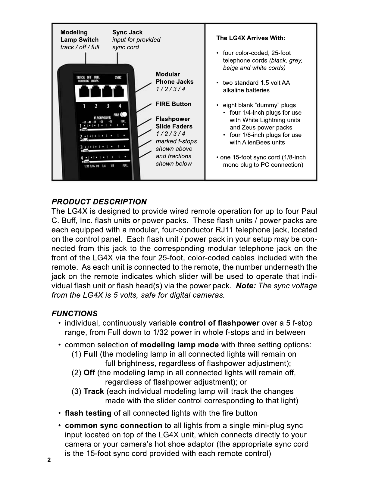
Modular
Phone Jacks
1 / 2 / 3 / 4
FIRE Button
Flashpower
Slide Faders
1 / 2 / 3 / 4
1 / 2 / 3 / 4
marked f-stops
shown above
and fractions
shown below
Modeling
Lamp Switch
track / off / full
Sync Jack
input for provided
sync cord
The LG4X Arrives With:
• four color-coded, 25-foot
telephone cords (black, grey,
beige and white cords)
• two standard 1.5 volt AA
alkaline batteries
•
• eight blank “dummy” plugs
• four 1/4-inch plugs for use
with White Lightning units
and Zeus power packs
• four 1/8-inch plugs for use
with AlienBees units
• one 15-foot sync cord (1/8-inch
mono plug to PC connection)

3
POWER
The LG4X is powered by two 1.5 volt AA alkaline batteries that are housed
in a snap compartment on the back of the unit. In normal use, the batteries
will last approximately 1000 hours before requiring replacement.
ON / OFF / “SLEEP MODE”
The
The LG4X does not have a traditional ON / OFF switch, but instead has a
Sleep Mode which will power down the unit after 3 hours of inactivity. When
the unit receives a sync command or a test command with the Fire button,
the Sleep Mode timer will reset. When in Sleep Mode, the sliders will not
control the flashpower or the modeling lamp. To begin your shoot, push the
fire button once to “wake” your remote.
TESTING
The
The FIRE button serves as a convenient way to test fire all flash units and
power packs connected to the LG4X. This test confirms that all units are cor-
rectly connected and correctly receiving commands while additionally testing
the battery condition and general functioning of the remote unit. Each time
the FIRE button is pressed, the red LED indicator on the remote should
briefly light (this LED is located next to the number 4 under the telephone
jack connections on the front panel of the LG4X). The red light indicates that
the
the battery is charged to an acceptable level and indicates that a diagnostic
test of the remote unit’s major internal components has been successfully
performed. The same diagnostic routine is carried out when the remote unit
has been fired via the built-in slave or sync jack. The LG4X need not be con-
nected to the flash units to be tested.
GETTING STARTED
To begin using the LG4X, you will need to have your flash units and flash
heads / power packs (with their various accessories) in place, with the indi-
vidual units connected to an AC power source.
1. In order to utilize the Modeling Lamp Switch on the LG4X, the
Modeling Lamp switch must first be engaged on the flash unit or
power pack. Ensure that each connected unit has the modeling
lamp turned ON.
2. Move the LG4X Modeling Lamp switch (located on the top of the
remote) to the “TRACK” position. This will provide a What-You-
See-Is-What-You-Get preview, where the modeling lamp in each
unit will track the changes that you make in flashpower. The lamp
will dim as the flashpower is lowered, and brighten as the flash-
power is raised. Should you wish to turn the modeling lamps off,
or keep them on full brightness throughout the shoot, you can
move this switch to change the setting at any time once your remote
control is in use.

4
GETTING STARTED continued...
3. To connect the first flash unit / power pack to the
remote control, plug one end of one of the
provided telephone cables into the telephone
jack on the unit’s control panel, and plug
the other end into the telephone jack on
the LG4X that is labeled with the number 1.
The first flash unit / power pack connected will
be “Unit 1.” The first slider control on the LG4X
that is labeled with a 1 will now control the
flashpower and modeling lamp settings of Unit 1.
4. Follow these same steps to connect up to three
additional units (Unit 2, 3 and 4). The color-
coded cables will visually indicate which unit in
your setup is connected to each labeled port.
5. Once your units are connected to the remote,
connect the remote to your camera with the
provided sync cord. This connection will give
the remote its cue to fire the connected unit when
your shutter is pressed.
6. With your flash units / power packs connected to
the remote and the remote connected to your
camera, you are ready to turn each unit ON and
begin shooting.
Note:
Note: While the remote connection will cue for your
flash units / power packs to fire as your camera shutter
is pressed, any other flashes of light in the area may still
trip your units. If you will be working around other pho-
tographers, use the provided “dummy” plugs to disen-
gage the built-in slave tripper on each connected unit.
The slave can be disengaged by inserting a dummy
plug into the sync jack on the unit’s control panel. With
the slaves disengaged, the units will only take their cue
to fire from the remote / your camera.
1/8”
1/4”
CONTROLS
When a flash unit or power pack is connected to the LG4X, control of the unit’s
Flashpower and Modeling Lamp Mode (Full, Off or Tracking) becomes a
function of the LG4X, regardless of the settings on the unit’s control panel.
When the LG4X is in Sleep Mode (or disconnected), control of these param-
eters reverts back to the individual unit’s control panel settings.

5
The controls and settings listed below for
each flash unit / power pack below are
not remotely operable and must be set
on the control panel for the individual unit:
AlienBees Flash Units (B400, B800 and
B1600) and Ringflashes (ABR800):
• the Power ON / OFF switch
• the Power ON / OFF switch
• the white MODEL LAMP ON switch
• the MODEL LAMP TRACK switch
• the MODEL LAMP CYCLE switch
White Lightning X-Series Flash Units
(X800, X1600 and X3200):
• the Power ON / OFF switch
• the Power Mode RANGE switch
• the Power Mode RANGE switch
• the white MODEL switch
• the Model = READY switch
White Lightning UltraZAP Flash Units
(UZ800 and UZ1600):
• the Power ON / OFF switch
• the white MODEL switch
• the Model = READ
• the Model = READY switch
White Lightning Ultra Flash Units:
• the Power ON / OFF switch
• the MODEL (tracking / full / off) switch
• the white Model switch
• the Relative Model switch
>> Note on using the LG4X with the
retired White Lightning Ultra units:
If sync voltage is an issue with using
your digital camera and the Ultra units,
the LG4X remote control can be used
as a safe sync between your digital
camera and the Ultra units. While the
Ultra Series units have a sync voltage
of 9.5 volts, the LG4X remote has a
sync voltage of only 5 volts.
Zeus Power Packs:
• the ON / OFF switch
• the POWER DISTRIBUTION switch
• the white MODEL ON / OFF switch
• the grey MODEL Cycle Monitor switch
• the blue
• the blue AUDIO Cycle Monitor switch
These controls / settings must be set to
the desired positions on each individual
unit. The unit must be turned ON before
remote operation can begin.
AlienBees ABR800 Ringflashes
AlienBees Flash Units
X-Series and UltraZAP Flash Units
Ultra Series Flash Units
Zeus Z1250 and Z2500 Power Packs

6
OPTIONS AND CUSTOM CONFIGURATIONS
If you would like longer cables for operation at further distances:
If
If you need to increase the distance between the flash units / power packs
and the remote, off-the-shelf modular telephone cables may be purchased at
local hardware stores and used. Make sure that these cables have four
internal wires, as cables with only two wires will not work. You may also use
two short cables to make one long cable by using an In-Line Cord Coupler.
The LG4X has been tested with wire runs up to 100-feet without problems.
If you wish to
If you wish to control more than four flash units with your LG4X:
If
If you would like to control more lights, an additional LG4X may be used to
control up to four more lights. Please note that multiple remotes may not be
wired to each other from one telephone jack on an LG4X to another tele-
phone jack on the additional LG4X. This will present a short circuit condition,
resulting in battery failure and possibly causing damage to the unit itself. If
you are using multiple remotes, only one needs to be synced directly to your
camera. The second set of remote-operated lights may then be adjusted
using
using your additional remote, but fired via their built-in slave trippers when
your camera sync orders the first set of lights to flash.
If you wish to control multiple units from one channel:
Another popular custom connection is to mount several lights in a large
overhead light bank and configure them to function as a single unit from
one channel of the LG4X. This can be achieved using modular adaptor that
allows multiple cables to be connected to a single phone jack (one IN,
multiple OUT), and may be purchased at a local hardware store. All flash
units linked to that channel will assume that channel’s slider setting.
If
If you plan to fabricate your own custom cables, keep in mind that standard
modular telephone cables require a reversal of the wire order on alternate
ends of each male-to-male connecting cable. Failure to follow this orienta-
tion will not harm the LG4X or the lights, but will prevent proper operation of
the system. Regardless of the configuration, your lights should always be
plugged into grounded, three-pronged power outlets. We recommend
against defeating the third-wire ground on Paul C. Buff, Inc. units, or any
other such equipment, for safet
other such equipment, for safety.
Please contact our Customer Support Team if you have questions about dif-
ferent setup options or custom configurations and would like assistance.
In-Line Cord Coupler:
A 4-conductor in-line
cord coupler may be
used to combine two
line cords (available at
local hardware stores).
Modular Adaptor:
4-conductor modular
adaptors (available at
local hardware stores
as 2-in-1 and 3-in-1
adaptors) may be used
to convert a single jack
to convert a single jack
to two or three jacks.

7
TROUBLESHOOTING
PROBLEM: the LED indicator does not light red
The
The LED indicator on the LG4X lets you know the status of the remote. A diag-
nostic test of the remote’s internal components is performed each time that the
unit is first used and a lit LED indicates successful results of this test. It also
indicates that the batteries are appropriately charged. When test flashing from
the LG4X using the Test button, if the LED indicator does not light red, first
check the batteries. The batteries that ship with the remote should last for
approximately 1000 hours before requiring replacement. To replace the batter-
ies, you will need two standard 1.5 volt AA alkaline batteries. You can use
rechargeable batteries, but they must be AA alkaline rechargeable batteries.
Always use batteries from a reputable manufacturer. After replacing the bat-
teries, if the LED still will not flash, an unlikely internal defect is indicated. If this
should occur, you will need to contact our Customer Support Team.
PROBLEM: the modeling lamp does not respond
If
If the modeling lamp on your flash unit does not respond with the remote, first
ensure that your modeling lamp is turned ON on the unit’s control panel. If the
modeling light is turned on but still does not respond and you hear a clicking
noise when you press the FIRE button, turn your flash unit off and disconnect
the remote. Ensure that the modeling lamp button is depressed on the flash
unit’s back panel, and move the Modeling Lamp switch on the remote control
to the “TRACK” position. Should you wish to turn the modeling lamps off, or
keep
keep them on full throughout the shoot, you can move this switch to change
the setting at any time once your remote is in use. The remote control
modeling lamp switch must begin in this “TRACK” position before a flash unit
is connected in order to function properly.
PROBLEM: sporadic flashing
Powering your light on multiple circuits can create problems, as different
circuits from different outlets may have different grounding or AC line noise. If
you have units in your setup connected to more than one power outlet, you
may see sporadic flashing when you connect the units to the LG4X. To prevent
this, keep all of the units plugged in to one power outlet, using a power strip.
This will ensure that the grounding for all connected units is the same.
Replacing the LG4X Batteries:
On the back side of the remote control is the
battery encasement. Slide the cover off and
remove the exhausted batteries. Replace the
exhausted batteries with two standard 1.5 volt
AA alkaline batteries or two standard AA alkaline
rechargeable batteries.
rechargeable batteries. Always use batteries
from a reputable manufacturer.

Typical LG4X Remote Control Setup
*It is best to use power sources that operate on a single
circuit. If the power outlets in the room are on multiple
circuits, try using a powerstrip to plug all of your units into
a power source operating on a single circuit. Powering
your units on multiple circuits can create grounding
problems and/or AC line noise.
60-Day Absolute Satisfaction Guarantee
2-Year Factory Warranty
This equipment is covered under a 2-year factory warranty. This warranty
is limited to the repair or replacement of a unit which fails during the period
stated. The warranty shall exclude the replacement of batteries, as these
will become exhausted over time based on normal use. Should warranty
will become exhausted over time based on normal use. Should warranty
service be required, you should first contact our Customer Service Team.
Toll Free Customer Service Line: 1-800-443-5542 or 1-877-714-3381
(Monday through Friday, from 9:00am to 5:00pm, CST)
 Loading...