

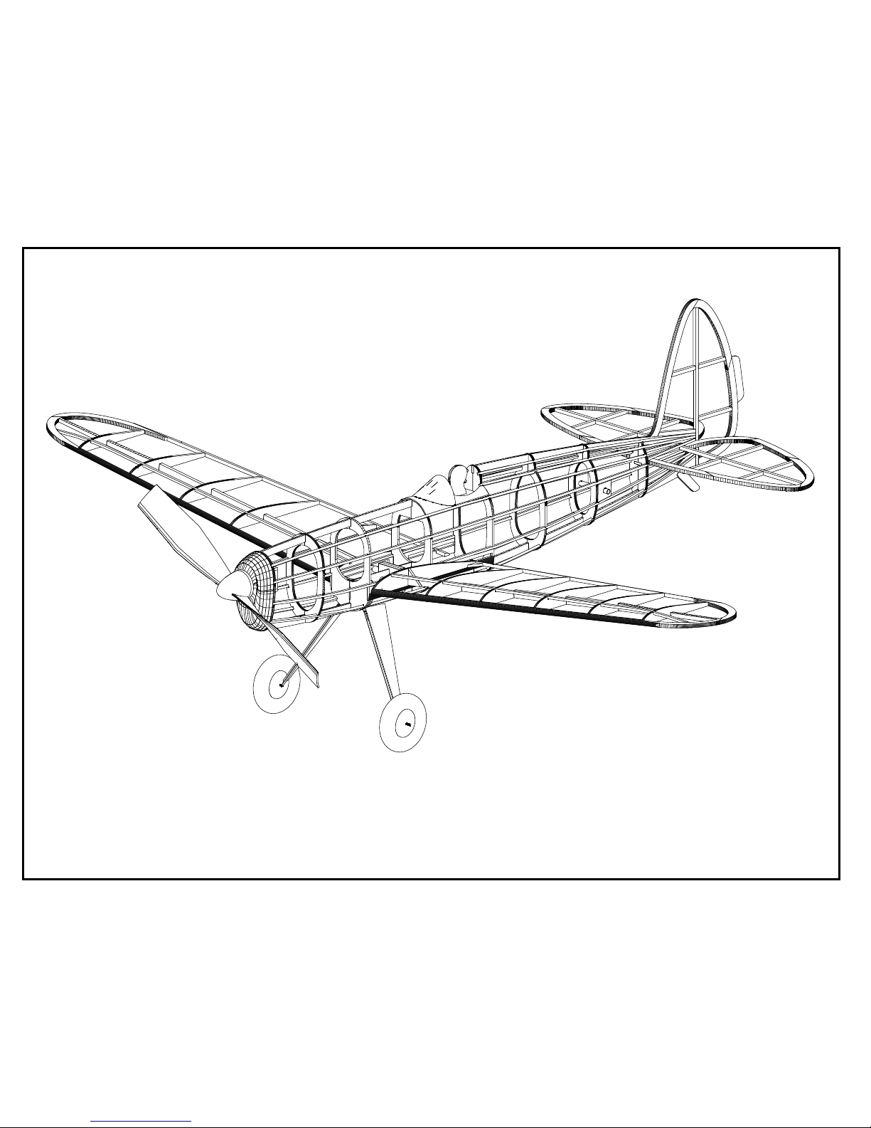
COMET SENIOR DART
REPRODUCTION
BY PAUL BRADLEY
ASSEMBLY GUIDE
JANUARY 2018
A RUBBER POWERED
24" WING SPAN MODEL
CHANGES MADE TO THE ORIGINAL
The following changes were made to the original Comet kit structural design. Most of the original kit design has been retained. The
changes made are intended to improve strength, make it easier to wind the model in a winding stooge, and in general take advantage of
techniques commonly used when building current day models.
1. The nose block has been set up for 3/32" blasa laminations rather than solid block.
2. The wing is set up to be removable rather than perminately attached to the fuselage. The ability to move the wing fore and aft hs been
retained.
3. A stab platform has been added to improve the strength and accuracy of the stab alignment.
4. 1/16" square sub spars have been added to the top of the wing to improve strength and to help reduce tissue sag between the ribs.
5. A motor peg has been used to anchor the rear end of the rubber motor as opposed to the method shown on the original kit plan. Sheet
balsa motor peg supports have been added.
6. Piano wire landing gear legs are used rather than straight pins through balsa legs. Retention of the landing gear legs has also been
strengthened.

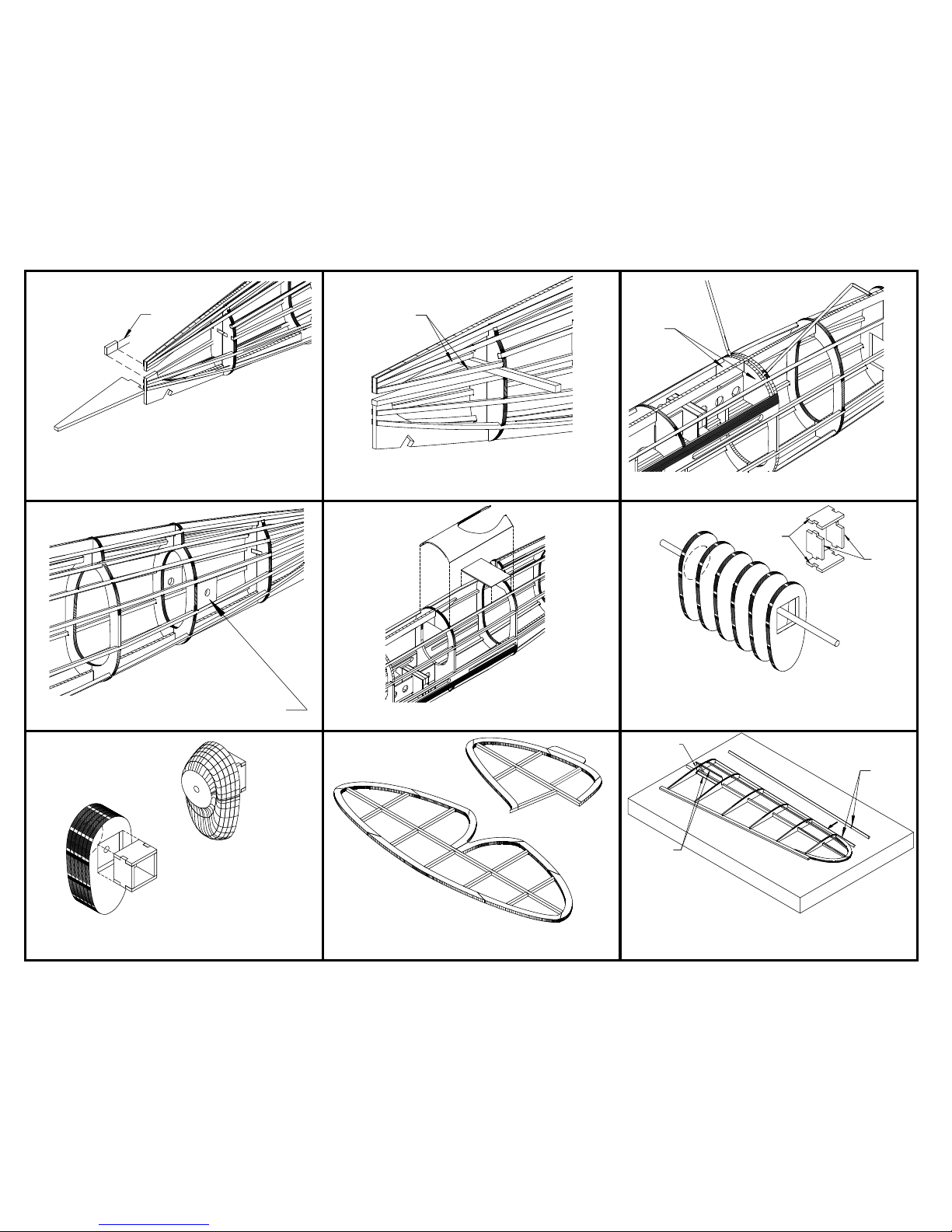
1.
Tape the six plan pages together to form three building plan pages.
Use the "+" marks for alignment of the pages.
Pin the keel parts to the plan. Glue the keel joints as the parts
are placed on the plan. Also glue the right former halves to the
keel using the plan as a location guide.
2.
3.
4.
5.
6.
7.
8.
9.
Remove the fuselage from the assembly fixture. Glue the top two
rear stringers on each side to the assembly.
Remove the fuselage assembly from the plan. Glue the wing
mount assembly to formers 3 and 4. Make sure the end of B-5
with the 3/64" hole faces former 3.
If you don't already have a fuselage assembly fixture, build one
like the one shown in the sketch. The cross pieces are held in
place with rubber bands. Place the fuselage on the fixture and
pin the keel to the fixture cross pieces. Add the main stringers
and the wing plate. Do not add the two top rear stringers at this
time.
Remove the fuselage assembly from the fixture. Flip the
assembly and insert the fixture cross pieces. Glue the stringers
in place. Again, do not glue the two top rear stringers to the
assembly at this time.
Assemble the wing mount components. The wing joiner slides
fore and aft on the plywood keel B-5. Make sure the wing joiner
moves easily on B-5.
1/64" Ply
5/32" OD
Aluminum
3/32" Balsa
Bend the landing gear legs from 1/32" piano wire. Insert the
gear legs through the hole in B-5. Glue the left side of each
former to the corresponding right side former. Line up the
landing gear legs and glue them to former 3.
3/64" Hole
Glue
Wing plate
Wing plate
Sand the stringers to a taper at the rear of the fuselage. Also
sand the wing plates so they blend with the fuselage curve.
Sand
These stringers
end at former 8
These stringers
end at former 8
3
10.
11.
12.
13.
14.
15.
16.
17.
18.
Remove a 5/32" wide piece from the rear of the lower keel piece.
Start at the joint between the lower and upper keel pieces. Glue
the stab platform to former 8 and the lower keel piece.
Glue formers 3A behind the landing gear legs.
Build the wing panels over the plan. Use W5 to set the angle of
rib A. The 1/8" diameter wing tubes are secured to the main
spar with strips of 1/16"x1/32" balsa.
Glue the nose block key to the back of the nose block. It fits inside
the square hole. Once the glue is dry, shape the nose block using
the plan top and side views as a guide.
Place a strip of 3/32" square balsa at the leading edge of the stab
platform. Glue a 1/16" square stringer on each side of the fuselage
as shown. Use the piece of 3/32" balsa as a guide. Once the
stringers are in place remove the piece of 3/32" balsa.
5/32"
Build the stab and fin. Sand the stab and fin to a symmetrical airfoil
shape (not shown in these illustrations).
Glue the motor peg supports to the fuselage on each side as
shown.
Add these
stringers
3A
Glue the pilot platform and 1/32" balsa cockpit faring to the
fuselage.
NB1
NB2
Flatten LE
here
1/16"x1/32" top
and bottom
W5
Glue the nose block laminations together. The lamination with the
square square hole is the back. The lamination with the circle
marked on a face is the front. Use a length of 1/8" dowel to align
the laminations. Remove the dowel before the glue sets. Also glue
the nose block key pieces together (NB1 and NB2).
19.
20.
21.
22.
23. 24.
25.
26.
27.
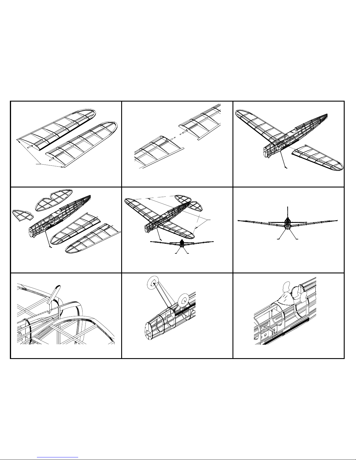
Remove the wing panels from the plan when the glue is dry. Shape
the LE, TE, and tips. Do not sand the TE extensions beyond rib A.
They ride in the wing plate slot and should remain rectangular.
A .1" x 1/8" round magnet is glued in center section end of each
wing panel aluminum tube. Orient the magnets so the wing panels
will attract each other. The tubes will have to drilled out for the
mgnets.
Check the fit of each wing panel in the wing joiner and the trailing
edge slots in the fuselage. Make any necessary adjustments.
Cover the wings, tail surfaces, and fusealge with tissue. Cut the
fuselage tissue away from the openings in the wing plates. This
illustration and subsequent illustrations will not show the tissue
covering.
Insert the wings into the wing joiner. Slide the stab into the stab
slot. Check to be sure the stab is square with the wings when
viewed from the rear. Adjust the stab slot if necessary. When the
alignment is correct, glue the stab in place.
Glue the fin to the fuselage. When viewed from the rear, make sure
the fin is vertical.
Glue the tail skid into the slot at the rear of the bottom fuselage keel
piece B-4.
Install the wheels. The original plan called out 1 1/2" diameter
wheels. Using 1" diameter wheels will be lighter and less drag. Also
install the landing gear leg covers. Wrap tissue around the covers
and leg wire to add strength.
Glue the pilot profiles to each side of the 1/16" balsa profile pilot
head. Glue the pilot head to the pilot platform. Also glue the
windshield to the fuselage using an adhesive like Forumula 560.
Equal
Lengths
DO NOT SAND
THE TE EXTENSIONS
The original kit did not show where the Center of Gravity (CG) should be placed. The wing is moved forward and back to achieve a
smooth glide slope when a loop of rubber is in the fuselage. The magnets in the wing tubes will pull the wing panels tight against the
fuselage. Once you have the best position for the wing established, mark the location on the fuselage. The wing joiner can also be
glued to the beam if desired.
28.
29.
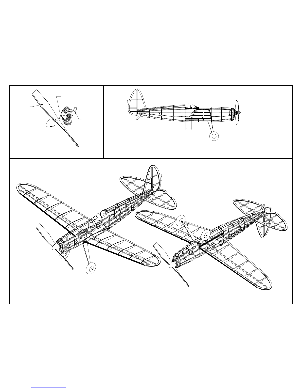
The propeller/nose block assembly is set up as shown. The prop
shaft hook can be your preferred style.
Peck thrust bearing
for 3/64" shafts
Spinner is optional
3/64" Piano wire
prop shaft
7" Prop
Move the wing forward and back
to obtain a smooth glide profile.
 Loading...