

Paul Universal Thermostat Operating Instructions Manual
Status: 02.10
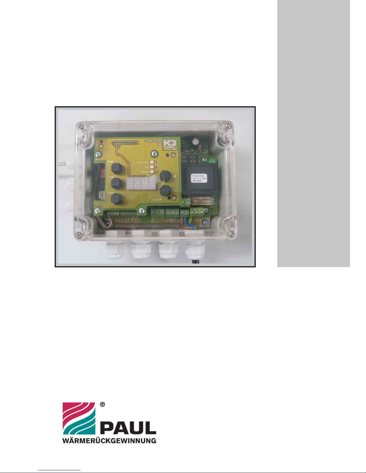
Universalthermostat
Self-sufficient control modul:
- Brine defroster / Motorised flap GHX
- Defroster heater
- Back up duct heater
fffff
Paul Wärmerückgewinnung GmbH
August-Horch-Straße 7
08141 Reinsdorf
Tel.: +49(0)375 - 303505 - 0
Fax: +49(0)375 - 303505 - 55
Deutschland
Operating InstructionsOperating
Instructions
P
lease keep next to the MVHR unit!
P
lease
keep
next
to
the
MVHR unit!
with modulating power control


Table of contents
0.
1.
2.
2.1
2.1.1
2.1.1.1
2.1.1.2
2.1.2
2.1.2.1
2.1.2.2
2.1.2.3
2.1.2.4
2.2
2.2.1
2.2.2
3.
Appendices:
Preface...............................................................................................................
Short description.................................................................................................
Function / Operation...........................................................................................
Operating modes................................................................................................
Continuous control for heating elements (Defroster heater / Backup duct
heater)…………………………………………………………………......................
Settings of operating mode pulse package control….........................................
Setting of temperature switching threshold and switching times........................
ON/OFF Control……..........................................................................................
Brine defroster / GHX flap control…………………………………........................
2-level control for defroster heater…………………….........................................
2-level control for backup duct heater………………...........................................
Settings of operating mode ON/OFF control......................................................
Interfaces……………………………….................................................................
External enabling…………………...………………………………………………...
Status message “Consumer load ON”
Error monitoring /-display...................................................................................
Technical data
Appendix 1 Connections / terminal diagram
Appendix 2 Connection brine defroster / GHX motorized flap
Appendix 3 Connection defroster
Appendix 4 Connection backup duct heater
Page
1
1
1
1
1
2
2
3
3
3
4
4
5
5
5
5
Date: 05.02.10
Subject to change in the interest
of technical progress.
OPERATING INSTRUCTIONS
Universal Thermostat
with modulating power control
© Paul Wärmerückgewinnung GmbH • August-Horch-Straße 7 • 08141 Reinsdorf • Deutschland
Tel: +49(0)375-303505-0 • Fax: +49(0)375-303505-55 • E-Mail: info@paul-lueftung.de • Internet: www.paul-lueftung.de
1
0. PREFACE
READ THESE INSTRUCTIONS CAREFULLY BEFORE USING THE EQUIPMENT!
This instruction contains all information necessary for an optimal installation, startup and. It can also be used
as a manual for maintenance and service work.
For the function and proper use of this device, all instructions in the assembly and operation instructions must
be followed strictly.
In case of disregarding these instructions, as well as the use of non-original parts, all warranty- and liability
claims are cancelled.
NOTE: This instruction has been made with greatest care. However, this introduction confers no
rights. We reserve the right to change all or part of the contents of this instruction without prior
notice.
1. Short description
The universal thermostat is used as a stand-alone control unit for the components brine defroster / GHX
regulating flap, defroster heater or electric backup duct heater. It has two programmable and independent
switching points (Temp 1 and Temp 2) with adjustable hysteresis.
The control for the electrical consumer is performed by an electronic relay, for electric duct heaters with
modulating power control. Pparallel to this a potential-free changeover is available. Enabling and locking of the
control can be performed by an external potential-free enabling contact. The programmed temperature values
as well as the temperature at the sensor are shown by a 7-segment display. Please see appendix 1: Electrical
connections / Terminal diagram.
2. Function / Operation
2.1 Operating modes
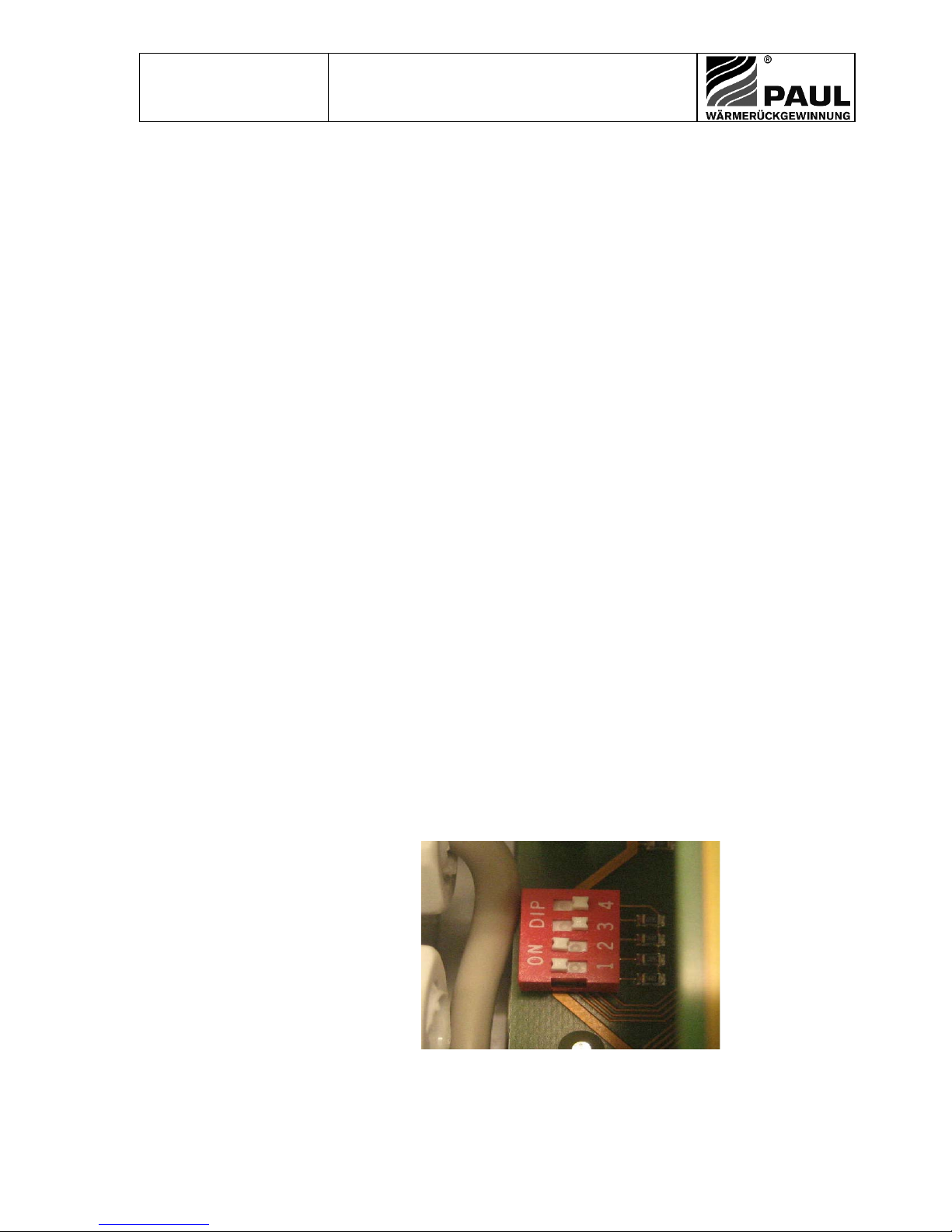
The configuration of the operating mode is done by DIP-switches. After selecting the new operating mode, the
control system has to be restarted (disconnection from supply).
2.1.1 Continuous control for heating elements (Defroster heater / Backup duct heater)
This operation mode is most suitable to achieve a constant air temperature even though the ambient
conditions are changing. The capacity of the heating element is modulated by the control system, so that
the temperature inside the air duct is always constant.
The temperature sensor is installed in the air duct (in air flow direction) downstream of the components
defroster heater / backup duct heater. The control of the brine defroster / GHX regulating flap depends on
the configured temperature threshold X1 (see appendix 1, appendix 3 and appendix 4):
ON: T ≤ X1
OFF: T ≥ X1+H
DIP-1, -2 ON
DIP-3, -4 OFF
T - Actual value of measured temperature depending on purpose:
- Intake air temperature downstream of defroster heater
- Supply air temperature downstream of backup duct heater
H - Hysteresis
X1 - Setpoint ″temperature switching threshold″
t - Cycle time pulse package control in seconds (s)
 Loading...