

Paul thermos 300 DC, thermos 200 Operating Instructions Manual
thermos 200 / 300 DCthermos 200 / 300 DC
Mechanical Ventilation Heat Recovery Unit
Operating InstructionsOperating
Instructions
P
lease keep next to the MVHR unit!
P
lease
keep
next
to
the
MVHR unit!
®
WÄRMERÜCKGEWINNUNG
with automatic control unit
Components
suitable for
Passive
House
Dr. Wolfgang Feist
Status: 07.09
Paul Wärmerückgewinnung GmbH
August-Horch-Straße 7
08141 Reinsdorf
Tel.: +49(0)375 - 303505 - 0
Fax: +49(0)375 - 303505 - 55
Deutschland


Table of contents
Part A Operating Instructions
Page
0.
1.
1.1.
1.2.
1.3.
1.4.
1.5.
1.6.
1.7
1.8.
2.
2.1
2.2
2.3
2.4
2.4.1
2.4.2
2.5
2.6
2.7
2.8
2.9
2.10
3.
3.1
3.2
3.3
4.
4.1
4.2
4.3
5.
5.1
5.2
6.
7.
7.1
Foreword.................................................................................................................
Brief product description.........................................................................................
Construction
Housing, heat insulation, soundproofing
Heat exchanger
Summer bypass
Ventilation fans
Filters ......................................................................................................................
Application limits
Flammability
Options and accessories.........................................................................................
Basis version
Motorised valve for ground to air heat exchanger ..................................................
Constant flow control
Ground to brine to air frost protection / electric frost protection heater
Ground to brine to air frost protection
Electric frost protection heater
Electric duct heater.................................................................................................
Hot water duct heater
Control for 1 heating circuit
External boost switch
External room temperature sensor
Additional programmer............................................................................................
MVHR Installation
Installation of the mechanical ventilation heat recovery (MVHR) unit – air duct
connections
Power supply / electric control
Connection and maintenance of the condensate drain hose G ¾” ........................
Start-up ...................................................................................................................
Readiness for operation
Balancing of air flows
Balancing of valves
Care and maintenance by owner (user) .................................................................
General
Filter change
Care and maintenance by service staff ..................................................................
Control unit..............................................................................................................
Operator comfort
1
1
2
2
3
4
5
5
6
7
8
8
8
Part B User Guidance – Automatic Control Unit
Page
1.
1.1
1.2
1.2.1
1.2.2
1.2.3
1.2.4
1.2.5
1.2.6
1.2.6.1
1.2.7
1.2.8
1.2.9
Menu structure and logical links..............................................................................
Basic menu
Menu - Settings 0....................................................................................................
Menu - Settings 0 - System Off
Menu - Settings - Enable 1.0 ..................................................................................
Menu - Settings – Filter change 2.0........................................................................
Menu - Settings - Temperatures 3.0
Menu - Settings - Programs/day 4.0.......................................................................
Menu - Settings - Programs 5.0
Menu - Settings - Edit programs 5.0.......................................................................
Menu - Settings - Date/time 6.0..............................................................................
Menu - Settings - Night reduction 7.0
Menu - Settings - Info 8.0........................................................................................
1
2
3
4
5
6
7
8
9

2.
2.1
2.2
2.2.1
2.2.2
2.3.
2.4
2.5
2.6
2.7
3.
3.1
3.2
3.3
3.4
4.
4.1
4.2
4.3
Menu System setup
Menu System setup – Frost prot.
Menu System setup - Bypass su/wi........................................................................
Menu System setup - Temperatures - Bypass su/wi
Menu System setup – Servomotor - Bypass su/wi.................................................
Menu System setup – Frost prot. brine pump / GHX valve
Menu System setup – Duct heater..........................................................................
Menu System setup – Ventilation steps..................................................................
Menu System setup – Factory settings...................................................................
Menu System setup – Enable 9.9.0
Service menu..........................................................................................................
Service menu 0 Temperatures
Service menu 1 Frost prot. / brine / GHX valve
Service menu 2 Back-up duct heaters....................................................................
Service menu 3 Summer/winter bypass
Appendix.................................................................................................................
Program structure with factory settings
Menu structure........................................................................................................
Fault messages.......................................................................................................
10
11
12
13
14
15
16
17
18
20
22
Part C Technical Description – Automatic Control Unit
Page
1
2
2.1
2.2
2.3
3
4
4.1
5
5.1
Introduction .............................................................................................................
Main Controller Unit (HCE)
HCE Basis Version .................................................................................................
Controller board terminal assignment.....................................................................
HCE Technical Data ...............................................................................................
Power pack .............................................................................................................
Switch module 2.1 kW ............................................................................................
Terminal assignment of switch module...................................................................
Programmer............................................................................................................
Definition and adjustment of parameters and functions via the programmer
1
3
4
5
5
6
7
8
Appendices
Appendix 1.1 Terminal assignment of control unit
Appendix 1.2 Internal terminal diagram thermos 200/300 DC
Appendix 2.1 External connection diagram thermos 200/300 DC
Appendix 2.2 Legend of external connection diagram thermos
Appendix 2.3 Cable description thermos 200/300 DC
Appendix 2.4 Instructions on electrical connection of thermos 200/300
Appendix 2.5 Electrical connection of thermos 200/300 DC
Appendix 3.1 Hot water back-up duct heater
Appendix 3.2 Installation instructions for electric back-up duct heater
Appendix 3.3 Installation instructions for flow sensors
Appendix 4.1 Cabling of programmer
Appendix 4.2 Cabling of hot water back-up duct heater pump
Appendix 4.3 Cabling of GHX valve
Appendix 4.3.a Cabling of frost protection brine pump
Appendix 4.4.a Cabling of electric duct heater with ohmic heating element
Appendix 4.4.b Cabling of ISO duct heater with PTC heating element
Appendix 4.5 Cabling of flow sensors
Appendix 4.6.a Cabling of frost protection heater with ohmic heating element
Appendix 4.6.b Cabling of ISO frost protection heater with PTC heating element
Appendix 4.7 Legend to cabling diagrams
Appendix 4.8 Sound insulation
Technical Data
Check list A Maintenance by owner/user
Check list B Maintenance by service staff
Air flow report

Status 14.07.09
We reserve the right to make
changes favouring technical
progress.
Operating Instructions
thermos 200 / 300 DC
with automatic control unit
®
WÄRMERÜCKGEWINNUN
G
© Paul Wärmerückgewinnung GmbH • August-Horch-Straße 7 • 08141 Reinsdorf • Deutschland
Tel: +49(0)375-303505-0 • Fax: +49(0)375-303505-55 • E-Mail: info@paul-lueftung.de • Internet: www.paul-lueftung.de
1
0. FOREWORD
READ THESE INSTRUCTIONS CAREFULLY BEFORE STARTING TO USE THE EQUIPMENT.
The present instructions contain the information necessary for operating an installation and the mechanical
ventilation heat recovery (MVHR) unit of the type thermos 200 / 300 DC. They also include maintenance
and service instructions.
This document is intended to teach you in a simple way how to use your heat recovery unit in the best way.
If any interventions into the MVHR unit are necessary, you are recommended to call in your installer.
The MVHR unit is subject to permanent improvement and development. So your equipment may differ in
minor details from this description.
We wish you much pleasure with your MVHR thermos 200 / 300 DC.
NOTE: This document has been prepared with utmost care. However, it confers no rights
whatsoever. We reserve the right to change all or part of the contents of this document without
prior notice.
1. Brief description
1.1 Construction
The compact mechanical ventilation heat recovery (MVHR) unit is delivered ready for connection. It
comprises the heat recovery unit, the control system and the associated programmer. A 3-metre long cable
is used to connect the MVHR unit with the control system. The link cable between the programmer and the
control unit may have a maximum length of 15 m and shall be provided by the customer who shall also
provide the control unit’s connection with the power supply.
1.2 Housing, heat and sound insulation
The fan and heat exchanger box subassemblies are releasably connected by means of assembly clips.
The entire housing consists of polypropylene (PP) foam and has no metal parts (full heat protection); the
components and subassemblies are embedded in the heat insulating foam material. The foam is also used
as sound absorbent material. It is recommended to connect a silencer (or 1...2 m long soundproofed flex
hose ∅ 250 mm) to each of the 4 air outlets of the unit (especially to those communicating with the rooms:
supply air and extract air). The air duct connections with the equipment must be flexible.
1.3 Heat exchanger
The specific design of the high-efficiency counter-flow channel-type heat exchanger, which is disclosed in
German and European patents, is such that the plastic ducts for the extract and supply air are arranged in
a checker board pattern, which provides a surface area twice the thermal efficiency of plate heat
exchangers; the two fluids (supply air and extract air) are hermetically separated from one another.
1.4 Summer bypass
The thermos 200/300 DC MVHR unit is equipped with a motorised bypass valve and a bypass shut-off
with safety functions for winter operation.
1.5 Ventilation fans
The unit comprises two electronically commutated maintenance-free 230 VAC radial fans with integrated
power pack. The specific power consumption thus achieved is as low as 0.36 Wh/m³ (Passiv Haus
certificate).
The air flow rates can be varied by the user. Please note that the short presence of just a few number of
people means low emission of CO
2
, humidity and smells into the room air and so it is possible to largely
reduce the air flow. A second beneficial aspect is that this avoids an excessively dry room climate when
outdoor temperatures are low (dry intake air).

Status 14.07.09
We reserve the right to make
changes favouring technical
progress.
Operating Instructions
thermos 200 / 300 DC
with automatic control unit
®
WÄRMERÜCKGEWINNUN
G
© Paul Wärmerückgewinnung GmbH • August-Horch-Straße 7 • 08141 Reinsdorf • Deutschland
Tel: +49(0)375-303505-0 • Fax: +49(0)375-303505-55 • E-Mail: info@paul-lueftung.de • Internet: www.paul-lueftung.de
2
1.6 Filters
The MVHR unit includes two Z-shape G4 filters (dust filters). They are made of a cotton/polyester fabric in
a frame. A high-quality pollen filter (rated F 8) can be used as an option in the supply air.
1.7 Application limits
The MVHR is designed for the use in residential and office buildings, in schools and retirement homes
(with certain limits in industrial application) at air temperatures of up to +40°C and normal air humidity.
Explosive and aggressive gases as well as solvents attacking the materials in the system are not allowed.
The unit has to be installed in a frost-free room. A ground to air heat exchanger would be advantageous
for pre-heating the intake air (in winter). If a ground heat exchanger is not feasible, a frost protection preheater or a ground to brine to air frost protection must be installed upstream of the unit.
1.8 Flammability
The housing of the unit is chiefly made of PP foam (normally flammable). Other components are hardly or
normally flammable (heat exchanger, ventilation fans); the filter with the cardboard frame (flammable) can
be considered a subordinate component. So the unit complies with the building regulations.
2. Options and accessories
2.1 Basic version
The compact mechanical ventilation heat recovery (MVHR) unit comprises the heat recovery unit itself, the
central control unit with power pack, and the programmer with display and room temperature sensor.
The control system with the programmer controls enables the user to freely select the minimum, normal
and maximum ventilation steps without limitation in time. But the ventilation steps can also be stored in 8
independent programs, which can be assigned to the different days of the week. This allows for fully
automatic operation with different fan power. The ventilation steps can be changed in 1% increments for
adapting the MVHR unit to the duct system. The supply and extract air flows are balanced via a coefficient
of correction allowing different fan speeds to be adjusted for the same ventilation step. The detailed
procedure is described in section 2.5 of the User Guidance of the Automatic Control Unit.
The summer bypass valve is series equipment. It is actuated via temperature sensors and the control unit.
It is used for automatically bypassing the heat exchanger in summer. The internal motorised bypass valve
is controlled as a function of intake and extract air temperatures.
The bypass is open e.g. t
EXT
> 23°C and t
INT
< t
EXT
(cooling function)
t
EXT
< 19°C und t
INT
> t
EXT
(heating function is possible too)
The temperature sensors are installed in the unit at the manufacturer’s site.
The bypass must be enabled (activated) and parameterised (see User Guidance of Automatic Control Unit,
Section 2.2).
To ensure the bypass valve functions properly, it is necessary to remove the supply air bypass shut-off
insert from the unit. For better tightness, the shut-off insert should be put back in place for the winter
period.
The MVHR unit can be switched off manually at the programmer without disconnecting it from the power
mains. This specific switching-off function limits the power input in standby condition to less than 2 W.
Furthermore, this automatically provides the necessary frost protection of any downstream hot water backup heater.

Status 14.07.09
We reserve the right to make
changes favouring technical
progress.
Operating Instructions
thermos 200 / 300 DC
with automatic control unit
®
WÄRMERÜCKGEWINNUN
G
© Paul Wärmerückgewinnung GmbH • August-Horch-Straße 7 • 08141 Reinsdorf • Deutschland
Tel: +49(0)375-303505-0 • Fax: +49(0)375-303505-55 • E-Mail: info@paul-lueftung.de • Internet: www.paul-lueftung.de
3
2.2 Motorised valve for ground to air heat exchanger
If a ground to air heat exchanger (GHX) is installed upstream of the MVHR unit on the intake side, a
motorised valve offers the option to take in the outdoor air either via the GHX or directly. Depending on the
outdoor temperatures (separate sensor required), the valve is set to air intake via GHX e.g. as follows;
Air intake via GHX at t
intake
> 25°C (cooling in summer operation)
Air intake via GHX at t
intake
< 5°C (pre-heating in winter operation)
The air is taken in directly (not via GHX) for all other temperatures (t
intake
= 5°C to 25°C). The temperature
sensor shall be placed close to the second intake point for recording the outdoor air temperature without
being heated by the sun. The sensor is included in deliveries with the control unit option “Motorised valve
for ground to air heat exchanger”.
The bypass has to be enabled, activated and parameterised (see User Guidance of Automatic Control
Unit, Section 2.3). The customer is responsible for connecting the valve to the power supply according to
the circuit diagram in Appendix 4.3.
Note: When a ground to air heat exchanger is used, this valve is not indispensable. The permanent current
consumption of the valve motor is about 50mA.
2.3 Constant flow control
The balance between the supply and extract air flows is crucial for proper operation of the MVHR system.
This flow balance is normally established by adjusting the fan power (ventilation step) and the correction
value. In constant flow control, analogue flow sensors are used to measure the two air flows, which are
then balanced by the constant flow mechanism. The advantage of constant flow control is that it adapts to
changing conditions and is independent of ventilation steps. Neither do fan motor irregularities (motor
winding, internal electronics) have an impact on the flow balance.
The constant flow control needs 2 analogue flow sensors to be integrated in straight tubes of the same
diameter (see Appendix 3.3 and Appendix 4.5).
When setting the parameters, it is possible to store a flow disbalance. The constant flow control has to be
activated and parameterised via the control unit in the menu System setup – ventilation steps (see User
Guidance of Automatic Control Unit, Section 2.5).
2.4 Ground to brine to air frost protection / electric frost protection heater
A ground to air heat exchanger / ground to brine to air frost protection, or a temperature-controlled frost
protection pre-heater should be used to prevent ice formation on the exhaust side of the heat exchanger.
Frost protection is indispensable.
2.4.1 Ground to brine to air frost protection
Depending on the outdoor temperature (separate sensor required), the pump of the ground to brine to air
frost protection is set as follows:
Pump ON: at t
intake
< 0°C (pre-heating in winter operation)
Pump ON: at t
intake
> 25°C (cooling in summer operation)
Pump OFF: at t
intake
= 5°C to 25°C (no pre-heating of intake air)
The temperature sensor shall be placed close to the second intake point for recording the outdoor air
temperature without being heated by the sun. The sensor is included in deliveries with the control unit
option “Ground to brine to air frost protection / Motorised valve for ground to air heat exchanger”.
The pump has to be enabled, activated and parameterised (see User Guidance of Automatic Control Unit,
Section 2.3). The customer is responsible for connecting the pump to the power supply according to the
circuit diagram in Appendix 4.3a.
2.4.2 Electric frost protection heater
To ensure frost protection, the air in the extract-exhaust section of the heat changer shall never fall below
the freezing point. If frost protection is provided by the electric pre-heater from PAUL, it will adapt
automatically to the changing conditions of the intake and exhaust air. The temperature of the exhaust air
is permanently recorded and evaluated. If the temperature of the exhaust air falls below 2°C, the intake air
will be pre-heated for so long until the exhaust air temperature exceeds 2°C again. This ensures optimum
energy supply and prevents the condensate from freezing. The installation of the frost protection heater is
described in Appendix 4.6. The heater with ohmic heating element shall be installed according to Appendix
4.6.a and the ISO heater with PTC heating element according to Appendix 4.6.b.

Status 14.07.09
We reserve the right to make
changes favouring technical
progress.
Operating Instructions
thermos 200 / 300 DC
with automatic control unit
®
WÄRMERÜCKGEWINNUN
G
© Paul Wärmerückgewinnung GmbH • August-Horch-Straße 7 • 08141 Reinsdorf • Deutschland
Tel: +49(0)375-303505-0 • Fax: +49(0)375-303505-55 • E-Mail: info@paul-lueftung.de • Internet: www.paul-lueftung.de
4
The control unit of the MVHR must be equipped for controlling a frost protection heater. The frost
protection heater has to be activated and parameterised via the control unit in the system setup menu (see
User Guidance of Automatic Control Unit, Section 2.1).
2.5 Electric duct heater
Electric or ISO duct heaters can be used as back-up heaters for the supply air. They are controlled via the
MVHR control system specifically equipped for this purpose. The duct heaters include the prescribed
safety appliances. A duct temperature sensor is used to limit the air temperature to 50°C, because higher
temperatures would cause dust particles to smoulder (undesired smells). The duct heaters are switched on
or off as a function of room temperature, duct temperature and temperature setpoint.
If the room temperature falls below the setpoint, the duct heater will start operating, and will stop when the
setpoint is exceeded. The room temperature is recorded by a temperature sensor in the programmer or by
an external room temperature sensor.
The setpoint is selected and the heater activated via the control unit (see User Guidance of Automatic
Control Unit, Section 2.4). A lower night-time temperature can be programmed. Connections shall be made
according to Appendix 2.1, Appendix 3.2, and Appendix 4.4.a for electric back-up duct heaters with ohmic
heating element, and to Appendix 4.4.b for ISO back-up duct heaters with PTC heating element.
Note: The control unit can operate only one heating circuit (electric duct heater, hot water duct heater, or
heating circuit)!
2.6 Hot water duct heater
A hot water duct heater can be used to heat the supply air. It is controlled via the MVHR control system
specifically equipped for this purpose. A duct temperature sensor is used to limit the air temperature to 50
°C, because higher temperatures would cause dust particles to smoulder. The duct heater is switched on
or off (hot water circulating pump) as a function of room temperature, duct temperature and temperature
setpoint.
If the room temperature falls below the setpoint, the duct heater will start operating, and will stop when the
setpoint is exceeded. The room temperature is recorded by a temperature sensor in the programmer or by
an external room temperature sensor.
The setpoint is selected and the heater activated via the control unit (see User Guidance of Automatic
Control Unit, Section 2.4). A lower night-time temperature can be programmed. Connections shall comply
with Appendix 2.1, Appendix 3.2, and Appendix 4.2.
Note: The control unit can operate only one heating circuit (hot water duct heater, electric duct heater, or
heating circuit)!
2.7 Control for 1 heating circuit (e. g. circulating pump for panel heaters or radiators)
The control unit of the MVHR must be specifically equipped for this purpose. A temperature sensor is used
to limit e.g. the flow temperature to 50°C (parameterisable). The heating circuit is switched on or off as a
function of room temperature, flow temperature and temperature setpoint.
If the room temperature falls below the setpoint, the heating circuit (pump) will start operating, and will stop
when the setpoint is exceeded. The room temperature is recorded by a temperature sensor in the
programmer or by an external room temperature sensor.
The setpoint is selected and the heating circuit activated via the control unit (see User Guidance of
Automatic Control Unit). A lower night-time temperature can be programmed. The connection shall be
made according to Appendix 4.2 as described for the hot water heating register.
Note: The control unit can operate only one heating circuit (heating circuit, hot water duct heater, or
electric duct heater)!
2.8 External boost switch
One or several boost switches can be connected with the programmer. Pressing the boost switch means
maximum fan power for 15 minutes. The connection shall be made according to Appendix 4.1.

Status 14.07.09
We reserve the right to make
changes favouring technical
progress.
Operating Instructions
thermos 200 / 300 DC
with automatic control unit
®
WÄRMERÜCKGEWINNUN
G
© Paul Wärmerückgewinnung GmbH • August-Horch-Straße 7 • 08141 Reinsdorf • Deutschland
Tel: +49(0)375-303505-0 • Fax: +49(0)375-303505-55 • E-Mail: info@paul-lueftung.de • Internet: www.paul-lueftung.de
5
2.9 External room temperature sensor
When using a duct heater or heating circuit, the programmer may have to be installed in a place other than
the reference space. It is then possible to install an external room temperature sensor to be connected to
the programmer according to Appendix 4.1. In such case, the internal sensor of the programmer needs to
be removed.
2.10 Additional programmer
The MVHR unit can be operated by several (maximum 5) programmers connected in series (e.g. one next
to the MVHR, a second one in the living room). If a duct heater is used, the room temperature is recorded
by the first programmer, i.e. the programmer closest to the control unit. The connection shall be made
according to Appendix 4.1.
3. MVHR Installation
3.1 Installation of the mechanical ventilation heat recovery (MVHR) unit – air duct connections
• Leave enough space to allow for filter changes and maintenance work.
• For better maintenance, use flexible hoses for direct air duct connections to the unit. We recommend
1 … 2 metre flexible silencer hoses ∅ 160 for proper sound insulation. The air ducts can be
connected to the MVHR unit from the side or rear (see Technical Data). Seal off any openings not
used in your system configuration with blind plugs and adhesive material (e.g. silicone) to create
airtight connections.
•
After each cleaning operation (every 2 years), re-assemble the fan box and the heat exchanger box
(press tightly) and lock them using the (blue) assembly caps.
•
Leave enough space for removing and putting back the blue assembly caps: 500 mm from the right
and 100 mm from the rear of the MVHR unit.
•
The MVHR unit should be raised (approx. 200 mm) from the floor to ensure sufficient slope if the
condensate is discharged over a longer distance.
• The MVHR unit must be installed in a frost free place!
• The MVHR unit should be placed on a heavy and solid plate for dampening vibrations and preventing
vibration transmissions to structures. Also, an expanded rubber mat (or similar soft material) can be
inserted between the plate and the MVHR unit. (Refer to Appendix 2 Sound insulation)
•
Check the filters are properly positioned: see arrow
Air ducts shall have heat insulation, no less than 50 mm, in the following cases:
• Cold air ducting in warm rooms (tape insulation to provide an airtight seal)
• Warm air ducting in cold rooms
Where appropriate:
• Frost protection pre-heater
• Air duct heater for back-up heating
3.2 Power supply / electric control
A 3 metre long control cable connects the thermos 200 / 300 DC MVHR unit with its control unit. A power
cord connects the control unit with a 230 VAC 50 Hz socket outlet to be provided by the user at the place
of installation of the control unit.
Important:
•
Never lay control cables to programmers and sensors next to 230/400 VAC cables (minimum
distance of 20 cm) and never lay out cables in loops.
•
Install the control unit in a way to ensure there is no heat build-up and sufficient space for
service access. Never enclose or “bury” the control unit (e. g. no flush mounting).
• The internal temperature sensor of the programmer must record the temperature of the room
air.

Status 14.07.09
We reserve the right to make
changes favouring technical
progress.
Operating Instructions
thermos 200 / 300 DC
with automatic control unit
®
WÄRMERÜCKGEWINNUN
G
© Paul Wärmerückgewinnung GmbH • August-Horch-Straße 7 • 08141 Reinsdorf • Deutschland
Tel: +49(0)375-303505-0 • Fax: +49(0)375-303505-55 • E-Mail: info@paul-lueftung.de • Internet: www.paul-lueftung.de
6
3.3 Connection and maintenance of the condensate drain hose G ¾”
Lay the condensate drain hose with continuous
slope (min 5%). Do not reduce its diameter. Make
sure the condensate can drip off freely at the end
with the hose being entirely emptied. If there is
risk of frost, the hose must be heated (tracer can
be delivered). Any rising or horizontal duct
connected to the exhaust air outlet shall be
provided with a condensate trap at its low point.
Also, ground to air heat exchangers need to be
trapped at their low point (refer to Figure 2).
Schematic sketch for condensate
discharge line with MVHR 90-thermos
Figure 1
Caution: U-bend traps can dry out!
Always refill water when:
• starting up the unit
• hearing a noise from trap (slurping noise)
• noticing smells from the sewage system in the building
• air passes through the trap
• a dry trap can be recommended and is available for delivery (preventing smells from getting into
the air in case of drying out)
If a low point cannot be avoided in the exhaust ducting between the exhaust air outlet of the unit and the
wall penetration, connect another condensate discharge there, because at low outdoor temperatures the
exhaust air is saturated with water vapour and causes drops to form at the inner walls of the duct. If a
silencer is installed at the exhaust outlet of the MVHR unit, it must form a top bend (
∩) to be protected
from condensate backflows from the exhaust air duct. The MVHR unit should be installed in a way to
ensure sufficient slope for proper condensate discharge over a longer distance.
Figure 2

Status 14.07.09
We reserve the right to make
changes favouring technical
progress.
Operating Instructions
thermos 200 / 300 DC
with automatic control unit
®
WÄRMERÜCKGEWINNUN
G
© Paul Wärmerückgewinnung GmbH • August-Horch-Straße 7 • 08141 Reinsdorf • Deutschland
Tel: +49(0)375-303505-0 • Fax: +49(0)375-303505-55 • E-Mail: info@paul-lueftung.de • Internet: www.paul-lueftung.de
7
4. Start-up
4.1 Readiness for operation
• Fill U bend trap with water
• Bypass shut-off (insert in autumn, winter, spring; remove in summer)
• Connect the control unit with the power supply, establish the electrical connections of the MVHR unit,
the programmer and the additional components with the control unit according to the circuit diagrams
(Appendix), observe the instructions (Appendix), the MVHR system is ready for operation
• Select the automatic mode
4.2 Air flow settings
Air flow settings are made via fan power adjustments with the bypass shut-off insert in place. (factory
setting: see Technical Data -Characteristics-) Select the appropriate characteristic curve for normal
ventilation (70%) according to the ductwork design (equal pressure loss for all duct runs, e. g. 100 Pa) and
the required total air flow, and adjust the fan power at the programmer. Supply and extract air flows can be
set to different values, e.g.: if a ground to air heat exchanger is used, it may be necessary to increase the
power of the supply air fan via the correction value. (for guidance: see User Guidance for Automatic
Control Unit).
4.3 Commissioning of valves (supply and extract flows)
• Set the fans to normal ventilation at the programmer
• Balance the air flows at the air valves using a capture hood and an anemometer (see air flow report)
• Set the ventilation slot at the valve, make sure it is not too narrow – risk of flow noise! Better: Reduce
the fan power or throttle the air flow early in the duct (install a throttle valve or a foam flow restrictor)
•
Balance the air flows at the MVHR unit (if required): Equal supply and extract flows (vary the fan power
to balance the flows), the extract flow may be slightly higher than the supply flow
• Readjust the valves
• Record the values in the enclosed “Air flow report”
5. Care and maintenance by owner (user)
(refer to check list A)
5.1 General
User maintenance is limited to the periodical cleaning of filters and supply and extract valves. Never allow
the MVHR system to run without filters. Therefore, always switch off the unit for maintenance. Pollen filters
should be replaced by the user immediately after the pollination period (depending on the pollen the user is
allergic to). Make a filter check after an operating time of 90 days. Filter change intervals according to
EN 1946-10 are 3 to 6 months. The filters can be obtained from PAUL; it is not possible to clean the filters
in place in the MVHR unit. The filter mats of the extract valves (e.g. bathroom, kitchen, toilet) shall be
replaced or cleaned (warm water with washing-up liquid) every 2 or 3 months, or at the user’s own
discretion after filter checks.
5.2 Filter change
Replace the supply and extract air filters in the MVHR unit when the message [CHANGE FILTER] appears
on the display of the programmer. The preset filter interval is 90 days. Other intervals can be programmed
at your own discretion (see User Guidance of Automatic Control Unit, Section 1.2.3).
To change filters, remove the two cover panels from the left front of the MVHR unit, the upper panel for the
extract filter and the lower panel for the intake air filter. The foam housing is provided with recessed grips
for easier handling. Each filter insert is masked by a plastic panel with grip band. Remove the panels.
Insert and position the filters correctly according to the prescribed flow direction (as identified by the
arrow ⇑) and the specified insert depth as shown in the associated labels. Then put all cover panels back
in place in reverse order.

Status 14.07.09
We reserve the right to make
changes favouring technical
progress.
Operating Instructions
thermos 200 / 300 DC
with automatic control unit
®
WÄRMERÜCKGEWINNUN
G
© Paul Wärmerückgewinnung GmbH • August-Horch-Straße 7 • 08141 Reinsdorf • Deutschland
Tel: +49(0)375-303505-0 • Fax: +49(0)375-303505-55 • E-Mail: info@paul-lueftung.de • Internet: www.paul-lueftung.de
8
6. Care and maintenance by service staff (see check list B)
According to DIN 1946/6 Chapter 6, the inspection and service interval is 2 years and includes the
following operations:
Filter check or change (see above) and cleaning of heat exchanger (HX). Cleaning is performed according
to level of contamination and maintenance interval every 2 years (important for 5-year warranty for the heat
exchanger).
Procedure:
1. Disconnect the MVHR unit from the power supply (de-energise).
2. Remove all assembly clips from the MVHR unit – remove air ducts from MVHR where necessary
3. Take off the top section of the heat exchanger box
4. Remove the heat exchanger box from the fan box by pulling it gently upwards and to the side.
5. Wash the heat exchanger by pouring warm water (< 50°C) with washing-up liquid through the two
air openings, turn the heat exchanger and repeat the washing process, then allow excess to drip
off.
6. In case of calcification, spray vinegar solution from the air inlet side onto the heat exchanger
surfaces in 3 applications 20 minutes apart, and then rinse with water in the end.
7. Check the condensate drain and clean, if required
8. Fill condensate trap with water
9. Re-assemble the MVHR unit in reverse order (Make sure the bypass shut-off insert points to the
front).
10. Re-connect the MVHR unit with the power supply (re-energise)
General inspection of the MVHR unit:
1. Contamination
2. Electrical safety
3. Leaktightness of condensate connection
The supply and extract air passages (valves) should be cleaned in this context.
7. Control unit
7.1 Operator comfort
Standard functions
• 8 independent time programs can be defined by the user and assigned to any day of the week
• motorised summer bypass valve
• manual stop in standby mode with limited power input below 2 W
• manual adjustment of ventilation steps (off, minimum, normal, maximum)
• programmer can be installed in any place in the house
• ventilation steps programmable in 1% increments (30-100% of maximum fan power)
• adjustable balance between supply and extract air fans
• filter monitor for change interval
• Freeze protection for downstream hot water duct heater
Options (with extra price for accessories)
• Control of an electric valve at the ground to air heat exchanger (either air intake through the ground to
air heat exchanger or direct air intake)
• Control of a frost protection pre-heater (frost protection heater prevents ice formation and thus replaces
a ground to air heat exchanger in winter)
• Constant flow control (permanent monitoring and balancing of the supply and extract air flows)
• and thus compliant with fireplaces
• Control of a heating circuit (e.g. heating circuit pump or electric back-up duct heater up to 2.1 kW) –
also with night reduction
• Several boost switches can be connected to the programmer.
The MVHR unit can be operated by several programmers (e.g. in the place of installation, another one
in the living room). If a duct heater is used, the room temperature is recorded at the first programmer.
Note: The description of the control menus can be found in the “User Guidance Automatic
Control Unit thermos 200 / 300 DC”.

Status 14.07.09
We reserve the right to make
changes favouring technical
progress.
User Guidance
Automatic Control Unit
thermos 200 / 300 DC
®
WÄRMERÜCKGEWINNUN
G
© Paul Wärmerückgewinnung GmbH • August-Horch-Straße 7 • 08141 Reinsdorf • Deutschland
Tel: +49(0)375-303505-0 • Fax: +49(0)375-303505-55 • E-Mail: info@paul-lueftung.de • Internet: www.paul-lueftung.de
1
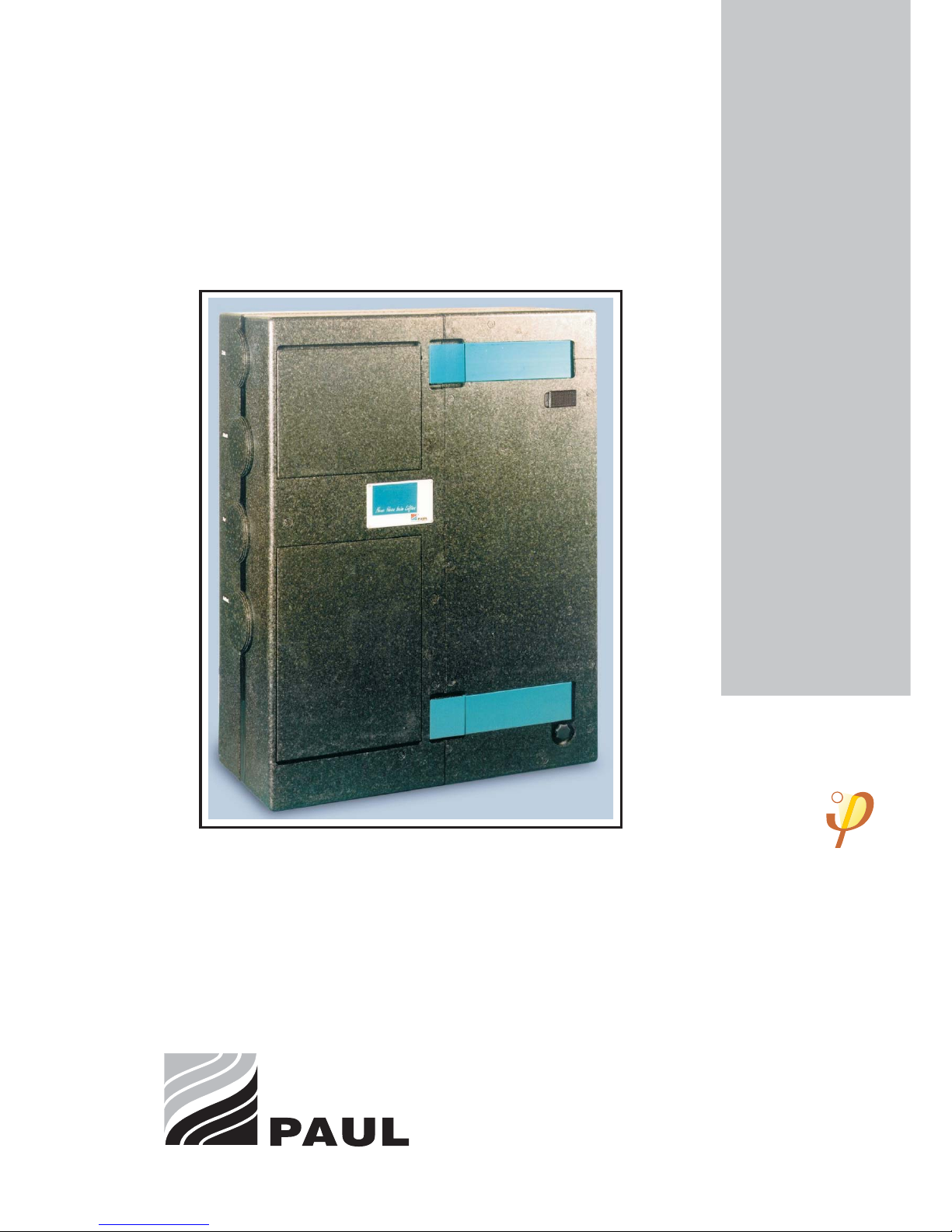
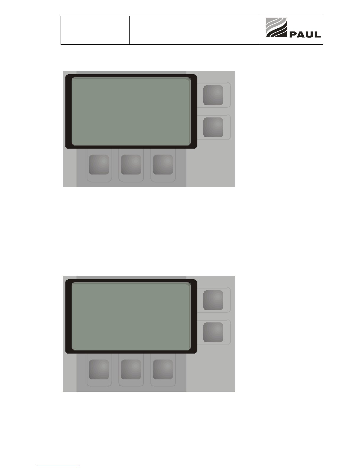
1. Menu structure and logical links
A graphical display of 128 x 64 pixels is provided for the menu dialogue. There are 2 buttons on the right
and 3 buttons in the lower section.
The display accepts both graphical characters and graphic pixels.
Graphical construction:
Fig: display in original size (158x125x32)
NOTE: All codes used programming descriptions are explained in Section C
“Technical Description of Automatic Control Unit”.

Status 14.07.09
We reserve the right to make
changes favouring technical
progress.
User Guidance
Automatic Control Unit
thermos 200 / 300 DC
®
WÄRMERÜCKGEWINNUN
G
© Paul Wärmerückgewinnung GmbH • August-Horch-Straße 7 • 08141 Reinsdorf • Deutschland
Tel: +49(0)375-303505-0 • Fax: +49(0)375-303505-55 • E-Mail: info@paul-lueftung.de • Internet: www.paul-lueftung.de
2
1.1 Basic menu
Room temperature is the temperature measured at the first programmer.
The item Ventilation shows the current mode: Manual or Auto
Step indicates the current power step for the ventilation fan as set by the selected program or chosen
manually.
Line 6 provides a clear text message in case of isolated faults or if the filter is to be replaced. In case of
simultaneous occurrence of several faults, an error code is indicated (refer to error code table). Pressing
the button TA2 illuminates the display screen for 1 minute.
Operating a boost switch connected to the programmer causes the ventilation to run at maximum power
for 15 minutes.
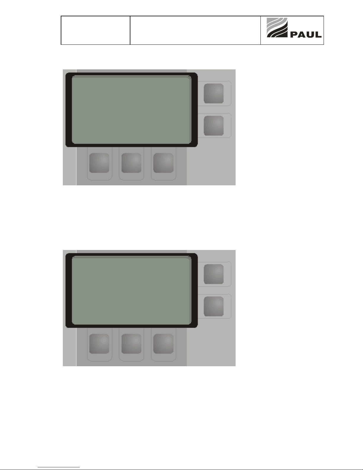
Basic menu: TA5 button
Pressing the button TA5 triggers manual minimum ventilation. Normal and maximum ventilation or the
automatic mode are adjusted in the same way. In the “manual” mode, no matter what timing program is
active, the ventilation step remains unchanged until you select another step or return to the automatic
mode. To change over to another step or back to the automatic mode, press the buttons TA3, TA4, and
TA5, respectively. The menu is accessible only in the automatic mode via TA1.
Mo 31.12 08:00 22.5°C
Program:xx Menu→
Ventilation: Auto
Step: normal
(error status) Light→
Ventilation to:
min normal max
TA1
TA2
TA3TA4 TA5
Mo31.12 08:00 22,5°C
Ventilation: manual
Step: min
Ventilation to:
Auto normal max
TA1
TA2
TA3TA4 TA5
Status 14.07.09
We reserve the right to make
changes favouring technical
progress.
User Guidance
Automatic Control Unit
thermos 200 / 300 DC
®
WÄRMERÜCKGEWINNUN
G
© Paul Wärmerückgewinnung GmbH • August-Horch-Straße 7 • 08141 Reinsdorf • Deutschland
Tel: +49(0)375-303505-0 • Fax: +49(0)375-303505-55 • E-Mail: info@paul-lueftung.de • Internet: www.paul-lueftung.de
3
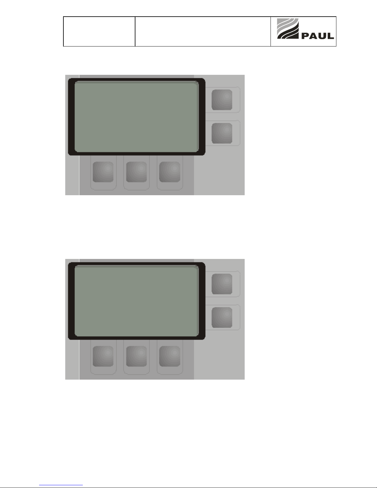
1.2 Menu - Settings 0
Scroll through the menu items with TA4 and TA5 (up/down arrows), press TA2 to select an item.
Press TA1 to return to the basic menu.
The pre-selected function is “System Off”.
1.2.1 Menu - Settings 0 - System Off
The control system is switched off, none of the sensors, modules and fans is monitored or controlled.
Reduced power input if the “standby” option is available. Press the TA4 button to switch on the control
system, which will start to run the auto program.
Settings 0
System setup
>Unit OFF< ←
Enable
Filter change
Temperatures
Programs/day
Programs
Date/time ok
Night reduction
Info
↓ ↑
TA1
TA2
TA3TA4 TA5
Unit is OFF
(Standby)
switch on
TA1
TA2
TA3TA4 TA5

Status 14.07.09
We reserve the right to make
changes favouring technical
progress.
User Guidance
Automatic Control Unit
thermos 200 / 300 DC
®
WÄRMERÜCKGEWINNUN
G
© Paul Wärmerückgewinnung GmbH • August-Horch-Straße 7 • 08141 Reinsdorf • Deutschland
Tel: +49(0)375-303505-0 • Fax: +49(0)375-303505-55 • E-Mail: info@paul-lueftung.de • Internet: www.paul-lueftung.de
4
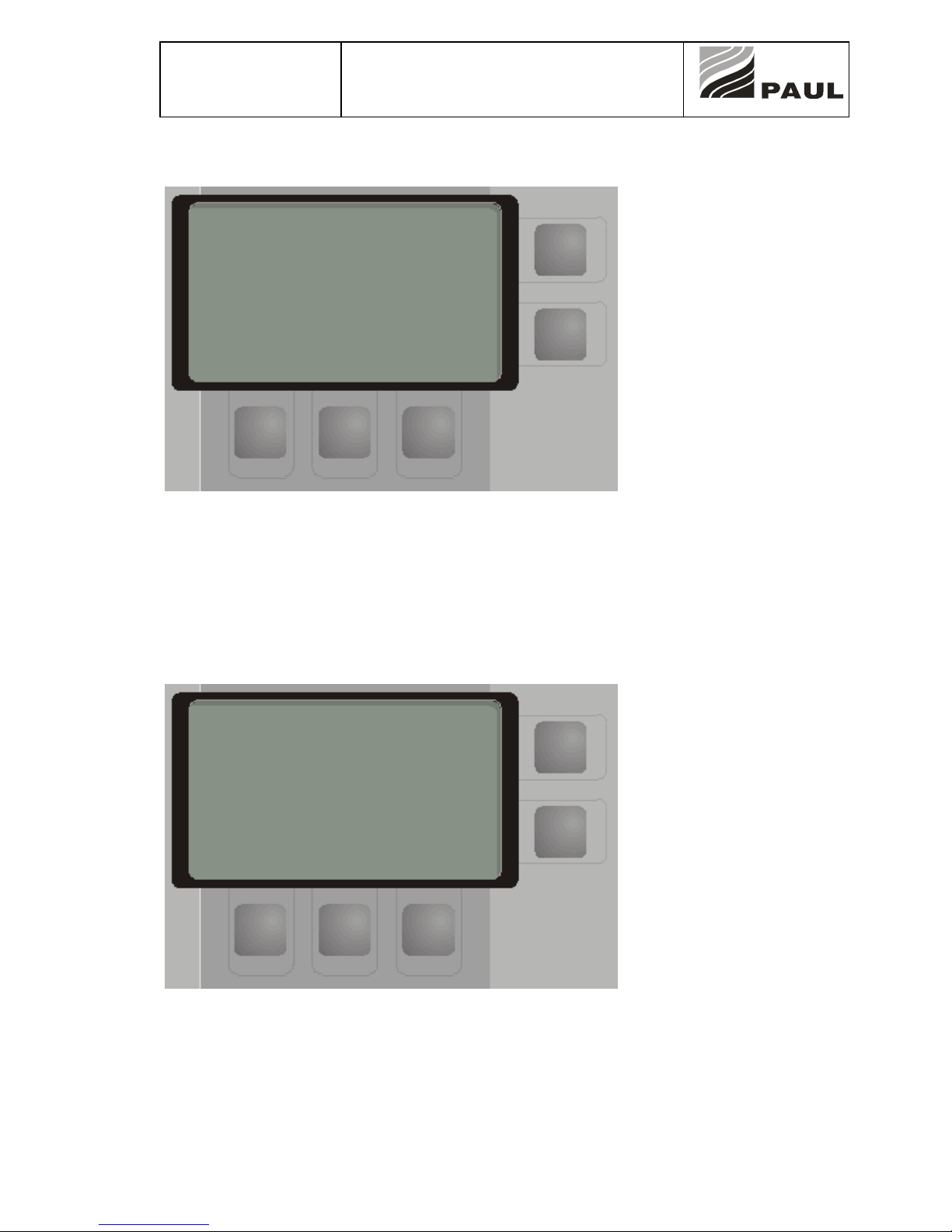
1.2.2 Menu Settings – Enable 1.0
In this menu, the user can activate or deactivate the modules existing in the given system.
Su/wi bypass: Controls a flap valve to bypass the heat exchanger.
Required condition: System equipped with a motorised bypass
Heating set to OFF
Heater: Controls a heating circuit, normally a duct heater.
Required condition: Control system is equipped for heater control.
Heater variants: - Hot water duct heater (pump is controlled)
- Electric duct heater (ohmic heating element is
controlled)
- ISO duct heater (PTC heating element is controlled)
- Static heating elements (pump is controlled)
Night reduction: Reduction of room temperature setpoint by a given difference at a given time.
Required condition: Control system is equipped for heater control.
Ventilation: Controls the ventilation fans
Press TA4 and TA5 (up/down arrows) to scroll through the menu items;
Press TA3 to select ON or OFF
Press TA1 to return to the previous menu.
The associated modules or devices are activated or deactivated via the software.
If this function is switched off, the related sensor readings are no longer evaluated.
Press TA1 to return to the menu Settings 1.
The current active functions of the system are displayed in the menu Enable only, not in the basic menu.
Interlocks: If heater is ON, the su/wi bypass remains closed.
Enable 1.0
←
Su/wi bypass: Off
Air heating: Off
Night reduction: Off
Ventilation: Off
↓ ↑ E/
A
TA1
TA2
TA3TA4 TA5
Status 14.07.09
We reserve the right to make
changes favouring technical
progress.
User Guidance
Automatic Control Unit
thermos 200 / 300 DC
®
WÄRMERÜCKGEWINNUN
G
© Paul Wärmerückgewinnung GmbH • August-Horch-Straße 7 • 08141 Reinsdorf • Deutschland
Tel: +49(0)375-303505-0 • Fax: +49(0)375-303505-55 • E-Mail: info@paul-lueftung.de • Internet: www.paul-lueftung.de
5
1.2.3 Menu Settings – Filter change 2.0
Menu for customising the filter change interval.
The filter change interval can be varied between 30 … 250 days. Press TA3 and TA4 (+,-) to increase or
reduce the number of days for the interval.
After reset, the day counter starts a countdown for the remaining service time.
After the interval has lapsed, the basic menu shows the message “Change filter” in line 6.
1.2.4 Menu - Settings - Temperatures 3.0
This menu is used to specify a setpoint for the room temperature (in heating operation, if a heater is
controlled via the control system).
The hysteresis for the switching processes can be changed in the system setup, but this should be left to
a specialist.
Example:
Room : 20°C
Temperatures 3.0
Room : → x0°C
→ - +
TA1
TA2
TA3TA4 TA5
Filter change 2.0
←
Interval: ->90 days
Change in->xx days
Reset - +
TA1
TA2
TA3TA4 TA5
Status 14.07.09
We reserve the right to make
changes favouring technical
progress.
User Guidance
Automatic Control Unit
thermos 200 / 300 DC
®
WÄRMERÜCKGEWINNUN
G
© Paul Wärmerückgewinnung GmbH • August-Horch-Straße 7 • 08141 Reinsdorf • Deutschland
Tel: +49(0)375-303505-0 • Fax: +49(0)375-303505-55 • E-Mail: info@paul-lueftung.de • Internet: www.paul-lueftung.de
6
1.2.5 Menu Settings - Programs/Day 4.0
This menu enables the user to assign different programs to the days of the week. So it is possible to run
Program 1 on working days, but to assign Program 2 to the weekend. The programs can be edited by the
user in the menu Programs 5.0.
Use TA5 to scroll through the weekdays and press TA3/TA4 to select the desired program number. Press
TA1 to return to the menu Settings 4.0.
1.2.6 Menu Settings – Programs 5.0
In this menu, you can open and adjust the eight available programs to your specific needs.
Press TA2 to scroll through the menu pages 1-3 for the programs 1-8.
Press TA3 to TA5 to open the program to be changed and select the ventilation steps (zero, minimum,
normal, or maximum) in 15-min increments.
Programs p.1/3 5.0
←
Select
Program number:
page 2→
01 02 03
TA1
TA2
TA3TA4 TA5
Program/day 4.0
←
- Monday -
Program: 01
↑
→ - +
TA1
TA2
TA3TA4 TA5

Status 14.07.09
We reserve the right to make
changes favouring technical
progress.
User Guidance
Automatic Control Unit
thermos 200 / 300 DC
®
WÄRMERÜCKGEWINNUN
G
© Paul Wärmerückgewinnung GmbH • August-Horch-Straße 7 • 08141 Reinsdorf • Deutschland
Tel: +49(0)375-303505-0 • Fax: +49(0)375-303505-55 • E-Mail: info@paul-lueftung.de • Internet: www.paul-lueftung.de
7
1.2.6.1 Menu Settings – Edit Programs 5.0
A program can be used to store a specific ventilation step for any quarter of any hour during a day. The
ventilation power steps are:
zero → No ventilation
min → Minimum ventilation
normal → Normal ventilation
max → Maximum ventilation
A system is generally designed and dimensioned for normal ventilation. So the minimum or zero steps
mean that there is less air exchange than assumed in the system design. On the one hand, there are
certain hygienic aspects – on the other, a reduced flow rate in association with a duct heater reduces heat
output.
Therefore, normal ventilation should be used most of the day.
Press TA3 to TA5 to select the desired time.
TA5 advances the cursor by 15 minutes, TA4 by one hour. TA3 sets the cursor back by one hour.
Use TA2 to assign the active time period to a ventilation step. You have the choice between zero, min,
normal, and max.
Edit program:01 5.0
←
00:00 → min
00:15 min
00:30 normal
00:45 max (+)→
+1/4h +1h -1h
TA1
TA2
TA3TA4 TA5
Status 14.07.09
We reserve the right to make
changes favouring technical
progress.
User Guidance
Automatic Control Unit
thermos 200 / 300 DC
®
WÄRMERÜCKGEWINNUN
G
© Paul Wärmerückgewinnung GmbH • August-Horch-Straße 7 • 08141 Reinsdorf • Deutschland
Tel: +49(0)375-303505-0 • Fax: +49(0)375-303505-55 • E-Mail: info@paul-lueftung.de • Internet: www.paul-lueftung.de
8
1.2.7 Menu Settings - Date/time 6.0
This menu is for setting the date and the time. This is important, otherwise the programs will not run
properly.
Press TA5 to scroll through the time and date until all values are set, then press “Save” to acknowledge
and store the values.
Save will appear on the screen when all settings have been made.
Press TA1 to exit the menu.
1.2.8 Menu Settings – Night reduction 7.0
The night reduction configuration is useful only if your unit includes a heating operated via the control
system.
The times and the temperature can be adjusted on an individual basis.
Select the numbers with TA5, change them with TA3 and TA4. Press TA1 to exit the menu.
Date/time 6.0
←
Time:18:25
↑
save →
→ - +
TA1
TA2
TA3TA4 TA5
Night reduction 7.0
←
22:00 - 08:00
↑
by x5.2°C
→ - +
TA1
TA2
TA3TA4 TA5

Status 14.07.09
We reserve the right to make
changes favouring technical
progress.
User Guidance
Automatic Control Unit
thermos 200 / 300 DC
®
WÄRMERÜCKGEWINNUN
G
© Paul Wärmerückgewinnung GmbH • August-Horch-Straße 7 • 08141 Reinsdorf • Deutschland
Tel: +49(0)375-303505-0 • Fax: +49(0)375-303505-55 • E-Mail: info@paul-lueftung.de • Internet: www.paul-lueftung.de
9
1.2.9 Menu Settings – Info 8.0
This is where the current temperatures are displayed for the user.
Press TA1 to return to the Menu Settings.
T-intake : Intake air temperature at the inlet of the unit
T-supply : Supply air temperature at the outlet of the unit
T-heat : Supply air temperature at the outlet of the duct heater
T-extract : Extract air temperature at the inlet of the unit
Opening any of the menus causes the unit and all extra components to be switched off. So the
temperatures shown here are representative only for the very moment the menu is opened in a stable
working condition of the ventilation system; longer waiting times will show temperatures different from the
actual condition.
T-intake : T1 °C
T-supply : T3 °C ←
T-heat : T5 °C
T-extract : T4 °C
TA1
TA2
TA3TA4 TA5

Status 14.07.09
We reserve the right to make
changes favouring technical
progress.
User Guidance
Automatic Control Unit
thermos 200 / 300 DC
®
WÄRMERÜCKGEWINNUN
G
© Paul Wärmerückgewinnung GmbH • August-Horch-Straße 7 • 08141 Reinsdorf • Deutschland
Tel: +49(0)375-303505-0 • Fax: +49(0)375-303505-55 • E-Mail: info@paul-lueftung.de • Internet: www.paul-lueftung.de
10
2. System setup menu
The system setup menu is used to make settings that are necessary for the configuration of the system
during the start-up phase. These settings shall be made by the authorised installer or by the service
staff of Paul Wärmerückgewinnung GmbH. Improper changes of the parameters offered in this menu
may cause undesirable effects or even incorrect operation of the system. Any customer service proven to
be caused by improper operator actions will be charged. The system setup is always programmed for the
highest configuration whether or not your specific system can use and evaluate all options mentioned
here.
----------------------- |System setup 9.0 |
| |
9 | Enable <-| TA1
0 |>Frost prot. heater < |
1 | Bypass su/wi |
2 | Brine/ground HX ok| TA2
3 | Heat pump |
4 | Solar |
5 | Duct heater |
6 | Buffer-max |
7 | Ventilation steps |
8 | W-setting |
| ↓ ↑ |
----------------------- TA5 TA4 TA3
Scroll through the menu items 9.0 to 9.9 using TA4 and TA5, select an item with TA2. Press TA1 to return
to the previous menu.
The menu items Heat pump, Solar and Buffer-max are available for the compakt 350DC series only. The
remaining menu items need the associated equipment installed.
2.1 Menu System setup – Frost prot. 9.0.0
---------------------- |Frost prot. 9.0.0 |
| <-| TA1
|PTC: yes/no |
|on: T7< -> (x1)°C |
|Hysteresis: (H1)°C |
| | TA2
| |
| -> - + |
---------------------- TA5 TA4 TA3
Press TA5 to select a value, and TA3 and TA4 to adjust it.
Example:
Adjustment: on: T7 < 2°C
Hysteresis: 1°C
Frost prot. On: T7 < 1.0 °C Secondary conditions Frost protection ON:
Frost protection enabled
Thermal cut-out ok*
Flow sensor Fz1 ok*
Power input Fz1 ok*
Temperature sensor T7 plausible
Ventilation enabled
Ventilation other than 0
 Loading...