

Paul TAC4 DG + TCP, TAC4 DG + TIP, TAC4 DG + GPRS, TAC4, TAC4 GPRS Operating Instructions Manual
Status: 06/2013
Operating Instructions
P
lease keep careful!
P
lease keep careful!
Paul Wärmerückgewinnung GmbH
August-Horch-Straße 7
08141 Reinsdorf
Tel.: +49(0)375 - 303505 - 0
Fax: +49(0)375 - 303505 - 55
Germany
Installation and maintenance
TAC4 DG + TCP/IP / GPRS


1
Table of contents
0
Preamble ................................................................................................................................. 2
1
Introduction ............................................................................................................................ 2
Safety ....................................................................................................................................... 2
1.1
Used symbols ........................................................................................................................... 2
1.2
2
Functionalities of the regulation .......................................................................................... 3
3
Operating principle ................................................................................................................ 4
4
Which module to choose – TCP/IP or GPRS? ..................................................................... 4
5
Configuration and programming of the TAC4 TCP/IP or GPRS module .......................... 5
Configuration file ...................................................................................................................... 5
5.1
Programming of the TAC4 TCP/IP or GPRS module from the SD card .................................. 5
5.2
6
Installation and connection of the TAC4 TCP/IP or GPRS ................................................ 6
7
PC Configuration to view web pages ................................................................................... 7
Compatible Web browser ......................................................................................................... 7
7.1
Installation of the “WebFormViewSetup.exe” viewer ............................................................... 7
7.2
8
Use of web pages ................................................................................................................... 7
Home ........................................................................................................................................ 7
8.1
Visualization ............................................................................................................................. 8
8.2
Synoptic ................................................................................................................................... 8
8.2.1
Alarms ...................................................................................................................................... 8
8.2.2
Setup ........................................................................................................................................ 8
8.2.3
m³/h+T° .................................................................................................................................... 8
8.2.4
I/O status .................................................................................................................................. 9
8.2.5
Configuration ............................................................................................................................ 9
8.2.6
Control ...................................................................................................................................... 9
8.3
Setup ........................................................................................................................................ 9
8.4
Time table .............................................................................................................................. 10
8.5
TAC4 Network ........................................................................................................................ 11
8.6
Configuration .......................................................................................................................... 11
8.6.1
Overview ................................................................................................................................ 11
8.6.2
Alarm warning ........................................................................................................................ 12
8.6.3
Logging .................................................................................................................................. 12
8.6.4

2
0 Preamble
PLEASE READ THIS MANUAL CAREFULLY BEFORE INASTALLATION AND COMMISSONING!
THIS MANUAL HAS BEEN MADE WITH GREATEST CARE.
HOWEVER, NO RIGHTS CAN BE DERIVED THEREFROM. WE RESERVE THE RIGHT AT ANY TIME
TO PARTIALLY OR ENTIRELY CHANGE THE CONTENT OF THIS MANUAL WITHOUT PRIOR
NOTICE.
This manual contains all the best for an assembly plant and a heat recovery unit (HRU) necessary
information. The manual also serves as a handbook for installation, maintenance and customer service
work. We recommend that any intervention in the appliance installation company should be consulted.
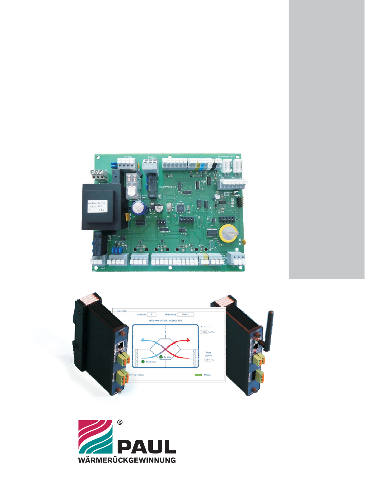
Subject of this operating manual is the control unit TAC4 and the modules TCP/IP and GPRS. Possible
accessories are only described insofar as it is necessary for the appropriate operation. Please see the
particular manuals for further information on accessories.
If you have any questions that have not been answered or have not been sufficiently answered in this
documentation, please contact the company Paul Wärmerückgewinnung GmbH. We will be glad to help
you.
1 Introduction
Safety
1.1
Please always observe the safety instructions in this operating manual. The non-observance of the safety
instructions, warning notices, notes and instructions can lead to injuries or damages to the maxi.
• Unless otherwise stated in this operating manual, only an authorised installer is entitled to install,
connect, put into operation and maintain the maxi;
• The installation of the maxi is to be performed according to the general local building, safety and
installation instructions of the corresponding local authorities, of the water works and electric
works and other official regulations and directives;
• Always follow the safety instructions, warning notices, notes and instructions described in this
operating manual;
• Please keep this manual during the complete life time of the maxi in proximity to the device;
• The instructions for the regular replacement of the filters or the cleaning of the supply and exhaust
air valves are to be strictly followed;
• The specifications stated in this document may not be changed;
• Any modification of the maxi is prohibited;
• In order to guarantee that the device will be regularly controlled, it is recommended to conclude a
maintenance contract. Your supplier can give you the addresses of authorised installers in your
area.
Used symbols
1.2
The following symbols are used in this manual:
Caution, special note!
Risk of: - injury of the user or the installer
- damages to the device
- impairment of the operation of the device if the instructions are not
carried out properly

3
2 Functionalities of the regulation
The TAC4 DG controller is mounted in the units of maxi-series.
The functionalities of this TAC4 DG control board are described in detail in the “Operating
instructions TAC4+RC” manual.
The TAC4 DG control board provides the following functionalities:
• Control of supply and exhaust fans in constant air flow (CA), constant pressure (CPs) and
constant airflow linked to a 0-10V signal (LS) mode.
• Management of 6 time slots.
• Default, set point and pressure alarms.
• Management of airflows in case of fire alarm.
• BOOST function that helps to force the supply and exhaust airflows to a value set beforehand-
overriding all configurations and conditions.
• Automatic management of the 100% bypass for free cooling.
• Automatic management of the opening and closing of valves mounted on the suction side.
• Anti-frost protection of the heat recovery exchanger by modulation of the supply airflow or by
regulating the power of the pre-heating electric coil (KWin).
• Regulation of the post-heating water (NV) or electric (KWout) coils to maintain a constant supply
temperature.
The following options can be combined with the TAC4 DG control board:
• Option SAT TAC4 BA/KW:
Regulation of 2 external heat exchangers (hot and/or cold).
• Option RC TAC4:
Local remote control that can be used for the configuration, display and control of the TAC4 unit
to which it is connected.
• Option SAT3:
Circuit with 2 relays for
- “Fans ON” and “Pressure alarm” signals (if in position O.R.1 / O.R.2)
or
"Circulator control” and “Bypass status signal” (if in position O.R.3 / O.R.4)
 Loading...