


P.AUDIO
2LINE-SUB – USER MANUAL


TABLE OF CONTENTS
1. Safety Precautions ..................................................................................................................... 3
2. Overview ................................................................................................................................... 4
2.1. Introduction ........................................................................................................................ 4
2.2. SYSTEM COMPONENTS .................................................................................................. 5
3. Features .................................................................................................................................... 6
3.1. 2LINE-6.............................................................................................................................. 6
3.2. 2LINE-Sub ......................................................................................................................... 6
4. Applications ............................................................................................................................... 7
4.1. Portable Stereo System ...................................................................................................... 7
4.2. Single microphone with 2LINE System ............................................................................... 8
4.3. 2LINE System for Installation.............................................................................................. 9
5. Set-up and Use of the 2LINE Sub ............................................................................................ 10
5.1. AC MAINS CONNECTION ............................................................................................... 10
5.2. AUDIO CONNECTIONS ................................................................................................... 11
5.2.1. Line Level Connection ...................................................................................................... 12
5.2.2. Microphone Level Connection .......................................................................................... 12
5.2.3. THRU Connection ............................................................................................................ 12
5.2.4. Speaker Level Connection................................................................................................ 12
5.3. Pre-set EQ Settings .......................................................................................................... 13
5.4. Turning on the System ..................................................................................................... 13
6. APPLICATION AND TROUBLE SHOOTING TIPS ................................................................... 13
7. PRODUCT SERVICE & WARRANTY ...................................................................................... 14
7.1. Replacement Components ............................................................................................... 15
8. Specifications .......................................................................................................................... 16
8.1. 2LINE-Sub ....................................................................................................................... 16
8.2. 2LINE-6............................................................................................................................ 17
9. Accessories ............................................................................................................................. 18

1. SAFET Y PRECAUTI ONS
READ ALL OF THE INSTRUCTIONS INCLUDED IN THIS MANUAL
The exclamation point within an equilateral triangle is intended to alert the user to the
presence of important operation and maintenance instructions.
The lightning flash with arrowhead symbol within an equilateral triangle is intended to alert
the user to the presence of un-insulated “dangerous voltage” within the product’s enclosure
that may be of sufficient magnitude to constitute a risk of electric shock to persons.
1. The following safety notices must be read and adhered to for safe operation of the 2LINE
range of products.
2. Copies of this manual should be retained by the system’s installer AND end-user.
3. This manual must be read and understood and ALL warnings must be followed.
4. Follow all instructions to insure optimal product performance.
5. The 2LINE-Sub is a convection-cooled device and requires at least 6 inches (152 mm) of
clearance behind the enclosure to allow the heat sink to adequately cool the internal
electronics.
6. DO NOT INSTALL NEAR ANY HEAT SOURCES!
7. Use ONLY the supplied AC Mains connector.
8. Protect the AC Mains power cord from being walked on or otherwise damaged and inspect for
damaged connections and damaged insulation.
9. The 2LINE-6 may be suspended. Use ONLY approved suspension hardware.
10. Do not suspend the 2LINE-Sub.
11. Do not substitute suspension hardware.
12. Suspension should be attempted by a professional that is familiar with local and national
codes and safe suspension practices!
13. There are NO user-serviceable parts inside the enclosure. DO NOT REMOVE THE
AMPLIFIER MODULE!
14. The 2LINE-6 and 2LINE-Sub must NOT be used in wet indoor or wet outdoor environments!
Use only in dry environments!

2. OVERVIE W
Point Source
2LINE
-6
2.1. INTRODU CTION
The 2LINE system is a high performance sound reinforcement system compromised of 2 loudspeaker
enclosures and associated rigging hardware. The 2LINE system brings a new level of performance
and ease of use to small event and fixed installations.
The P.Audio 2LINE system compromises 2 cabinet designs plus a variety of rigging options to suit
many different scenarios of portable and installation use.
The core of the system is the 2LINE-6 column loudspeaker which makes use of 6 2” diameter
loudspeakers with amplitude shading to create a line source array. The low end is provided by the
2LINE-Sub powered cabinet, which features a solid wooden cabinet with 300w of amplification
available for the 10” woofer. The amplifier also has a powered output, allowing the 2LINE-Sub to also
power the 2LINE-6 column array with 300w of amplification. Together, the 2LINE system boasts
600w of power in a tiny package.
The benefits of the line source are both visual and practical. The slim, discreet appearance of the
2LINE-6 cabinet is of great benefit when the installation requires unnoticeable sound reinforcement,
such as in houses of worship or art galleries, restaurants and pubs. In difficult acoustic environments,
the very controlled vertical directivity of the column ensures minimal reverberation.
Horizontal
Dispersion
Vertical
Dispersion

2.2. S YSTEM C OMP ONENTS
The 2LINE-6 cabinet is constructed from steel sheet, which has been accurately laser cut and formed
using state of the art fabrication techniques. 7 Separate parts are then combined and precision
welded to form the basis of the cabinet. This cabinet is then galvanised and powder coated with a
very durable black or white finish. This new method of cabinet construction ensures the product is
very strong, durable, and allows the cabinet to support the weight of ONE additional cabinet when a
longer column system is desired.
The 2LINE-6 also features switchable impedance for use in distributed systems. Standard column
impedance is 4 ohms, for use with the 2LINE-Sub, but once the 16 ohm impedance is selected, up to
4 cabinets can be linked to either the 2LINE-Sub output channel or another 4 ohm stable amplifier.
The 2LINE-Sub is an actively driven 10” subwoofer with on board DSP with selectable EQ presets,
and a high passed speaker level output to feed the 2LINE-6 column loudspeaker.
The 2LINE System has 3 main rigging options:
2L-PTB (2LINE PAN/TILT BRACKET)
The 2LINE PTB bracket allows for up to 15 degrees of tilt and +/- 15 degrees of pan when mounted to
a wall. The wide horizontal directivity of the 2LINE column array means that extreme degrees of
panning are not required. The limited pan settings ensure that the bracket does not extrude too far
behind the array, ensuring that the system stays as visually discreet as possible.
2L-SPA (2LINE SPEAKER POLE ADAPTOR)
The 2L-SPA is intended for use in portable systems when the 2LINE-Sub is used as the system base.
The stand adaptor allows for either 0 or 10 degrees of down tilt. It is generally recommended that the
system be used with 10 degrees down tilt to ensure proper front to back venue coverage.
2L-LB (2LINE LINK BRACKET)
The 2L-LB Link bracket is designed for use when taller array systems that 1 cabinet is desired. It is
NOT RECCOMENDED to link more than 2 cabinets at one time. The Link bracket has tilt capabilities
up to 15 degrees in 5 degree increments. The 2L-LB is not certified for use with in conjunction
with the 2L-SPA! DO NOT LINK MORE THAN 2 COLUMN ENCLOSURES!

3. FE ATURE S
3.1. 2 LIN E-6
High directivity vertical column array
6 closely spaced 2” radiating elements
Neodymium based transducers
Switchable 4 ohm or 16 ohm operation
Multiple rigging accessories
High power handling transducer elements
3.2. 2 LIN E-SUB
10” Actively Driven Subwoofer Enclosure
Speaker Level Output for easy system set up
Optimised for use with the 2LINE-6 Column Loudspeaker
Universal, very stable SMPS and Class D amplification with on board DSP
8 presets for switchable performance in every situation
Solid wood construction
Small, yet powerful system

4. APPLI CA TIONS
4.1. P ORTAB LE STERE O SYS TEM
The combined 2LINE system is an ideal system for quick, easy set up at small events. The on board
amplification ensures system cabling is kept to a minimum for discreet sound reinforcement at
corporate events, wedding receptions and other events.

4.2. S INGLE MICROP HONE W ITH 2 LINE SYSTE M
The XLR input on the 2LINE sub can be switched between microphone and line level sensitivity. The
on board EQ pre-sets ensures that clear vocals can be achieved when set to the ‘Vocal’ pre-set.
CHECK!

4.3. 2 LIN E S YSTEM FOR INST ALLATI ON
Up to 4 x 2LINE-6 cabinets may be linked when configured for 16 ohm nominal impedance. This is
ideal for distributed fixed installation requirements when combined with the rigging accessories in the
2LINE system. For optimal sound balance it is recommended that 2 2LINE-6 cabinets are linked from
each 2LINE-Sub whilst in 16 ohm configuration.

5. SET-UP AND U SE OF TH E 2LINE SUB
Before setting up your 2LINE Active speaker system, here are some general rules of thumb that you
should always bear in mind:
Make all audio connections before powering your speakers to avoid high level transients making their
way to the speakers. The speakers should then be the first thing you turn off after operation is
finished.
Ensure you have all gain stages set at the appropriate levels. The sensitivity of the line level input
section on 2LINE products is designed to work best at 0dBu (0.775V).
Ensure clipping is avoided at all gain stages of the system to ensure distortion free sound.
The power supply for the 2LINE-Sub amplifier is a universal type, which will
automatically detect if running off 230v or 115v mains. Ensure that mains voltages
are not above 264v or below 81v for stable use of the 2LINE-Sub.
Ensure any replacement fuses fitted are of the same type and rating as the one
supplied by the factory. The rating should be F5A 250V SLOW BLOW (5AL250VP)
5.1. AC MA INS CON NECTION
Prior to connecting the AC mains cable, ensure that the AC mains switch is in the OFF position. The
2LINE-Sub uses a standard IEC-type AC mains connector system. To mate the AC mains cable with
the AC mains connector on the amplifier, simply align the plug with the panel’s connector and press
the AC mains cable into place. Always support the enclosure with one hand whilst performing this
operation. The AC mains connector is shown above. To disconnect the cable end of the AC mains
connector pull back on the molded plug at the end of the cable, not the cable itself. Once the cable
has been connected, check that the amplifier pilot light is lit on the rear panel.
NOTE: If the pilot light does not illuminate within 30 seconds the unit may have a fault. If this
occurs, the unit should be returned to P.Audio for evaluation.
THERE ARE NO USER-SERVICABLE PARTS INSIDE. DO NOT REMOVE THE
AMPLIFIER MODULE! (See the section below “Replacement of Components” for more
detailed information).

NOTE: ALWAYS turn off the AC mains power BEFORE attempting to disconnect the AC
mains cable from the 2LINE amplifier module!
NOTE: DO NOT CONNECT THE AC MAINS END OF THE AC MAINS CABLE IN AN AREA
THAT IS WET OR SUBJECT TO CONDENSATION OR DAMP CONDITIONS!
Once the AC mains cable is securely connected to both the amplifier and AC mains supply, the
amplifier may be turned on. It is good practice to make certain that the audio levels on the mixer’s
output (or other source output) are reduced or muted prior to applying power.
5.2. A UDIO CONNECTIONS
The image below illustrates the 2LINE-Sub input plate. The audio input and link output connectors are
shown, along with the input sensitivity selector, pre-set selection knob and ground lift switch.
5.2 .1. LINE L EVEL CONNECT ION
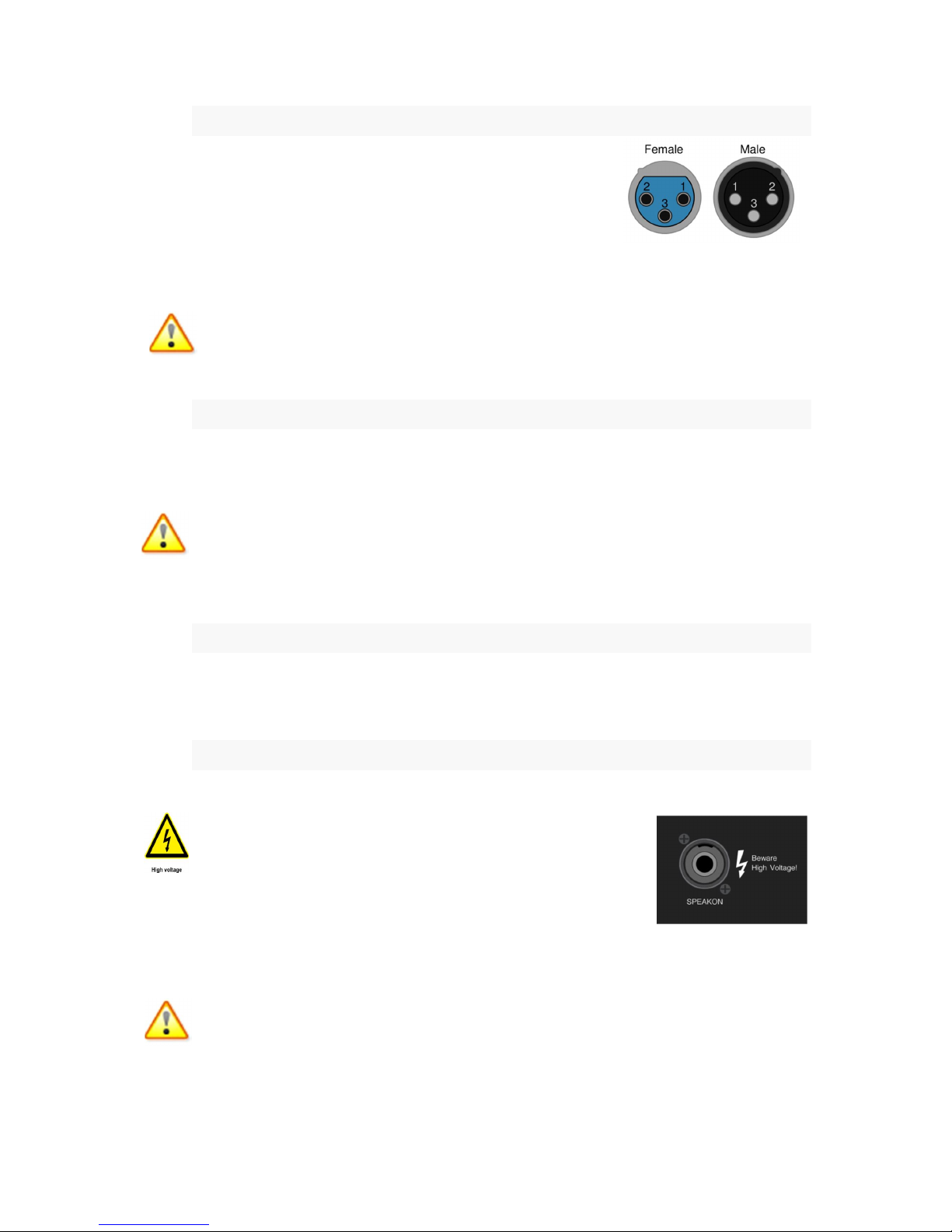
The 2LINE-Sub includes both male and female XLR-type connectors.
Any standard XLR-type cable end connectors may be used. For best
noise rejection performance from the cable, it is recommended that only
balanced cables are used. For both the input and output connectors,
pin 2 is considered positive.
The sensitivity selection switch must be set to line level, which is indicated by the silk screen artwork
on the amplifier panel.
It is reccomended that the level control knob be turned anticlockwise to it’s minimum point, to
avoid sharp clicks and pops when connecting the XLR cables to the 2LINE System.
5.2 .2. MIC ROPHONE LEVEL CONN ECTION
For microphone level connection to a dynamic microphone, the sensitivity switch on the XLR input
should be set to ‘Mic’, whilst the gain control knob is set to its minimum setting. It is recommended
that the vocal preset be used when connected directly to a microphone in order to reduce feedback.
Note that only dynamic microphones can be used, as the 2LINE –Sub is not capable of
providing phantom power on the input XLR.
NOTE: Do not stand directly in front of the 2LINE system when using a microphone in order to avoid
Audio Feedback, which can damage the transducer components!
5.2 .3. THR U C ONNECTI ON
The XLR THRU connector allows the XLR audio signal to be passed THRU to another XLR input.
This allows easy daisy chaining for full system scalability. Ensure the gain control is set to a minimum
(or power turned off) on subsequent items in the signal chain to avoid clicks and pops.
5.2 .4. S PEAKE R L EV EL CONNECTION
The Speaker Level Output on the 2LINE-Sub amplifier panel is
capable of outputting high voltages! Take caution when connecting
cables to the connector!
The speakon connector is a locking connector. Any 2 or 4 pole speakon
connector may be used to link between the 2LINE-Sub and the mid hi
cabinet. The output from the 2LINE-Sub is on pins 1+/1- of the speakon connector. To insert the
cable into the 2LINE-Sub, insert the connector until fully into the socket, then turn the connector
clockwise until it clicks into position.
NOTE: take extreme caution when walking around loose cables with locking connectors.
Simply pulling on the connector will not release it, and too much force can damage the
connector and amplifier unit.

When used with the 2LINE-6, the other end of the speaker cable may connected into either socket.
The spare socket on the 2LINE-6 may be used for dasiy chaining enclosures together in parallel.
When using 2 or more 2LINE-6 cabinets with the 2LINE-Sub amplifier, ensure the
impedance selection switch is set to 16 ohm operation!
5.3. P RE-SET E Q SETTINGS
The 2LINE-Sub has 8 pre-sets which are optimised mainly for use with the 2LINE-6 column
loudspeaker. These are clearly described on the rear panel of the 2LINE-Sub. Pre-sets 1-4 provide
different voicing modes for use with the 2LINE-6, with pre-set 4 intended for spoken word usage. It is
recommended to use the 2LINE-6 column loudspeaker in most situations.
The P.Audio 2LINE-Sub can also be used in fixed installation environments with other loudspeakers
from the P.Audio fixed installation range to provide amplification, and low frequency extension. The
presets dedicated to this are presets 5 – 8. The 2LINE-Sub is ideally coupled with Gallardo-4, and
the Compact range of loudspeakers. These pre-sets simply provide a flat high pass output, so ensure
the connected loudspeaker is a good quality point source design to ensure the entire system will
sound as expected.
5.4. TURNING ON T HE SYSTE M
After all audio and power connections have been made, the gain control is at minimum, and all cables
have been double checked, it is safe turn on the 2LINE-Sub. Press the switch from the ‘off’ to the ‘on’
position. Due to the soft start mechanism in the 2LINE-Sub amplifier, do not be alarmed if the audio
takes a few seconds to radiate. After a few seconds, the gain control on the back of the amplifier may
be slowly increased to the desired level. Please note that for typical installations it is likely that there
will be multiple gain stages in the system. The “source” gain should also be low for initial power-up of
the 2Line-Sub. (i.e., the source mixer output or source program material output gain function.)
Warning: High level listening levels for extended periods of time can cause hearing damage.
Please take care to keep the listening level to sensible levels.
6. APPLI CATION AND TROU BLE S HOOTING TIP S
The 2LINE System is a high-quality professional sound reinforcement system designed for use in both
indoor, and dry outdoor applications. Some basic precautions will insure long-term reliability.
DO NOT USE IN OUTDOOR/WET ENVIRONMENT
PROBLEM: Distorted sound
When input levels to the 2LINE amplifier exceed 0.775 V RMS for line level inputs (or 3mV for mic
level inputs) it is possible to produce system clipping or overdrive. Although the DSP processor has
input limiters, it is still possible to “overdrive” the input section of the enclosure. If distorted sound is
present the following steps should be taken.
1. Verify that the mixer’s output is not clipping or overloaded. If the output metering section of
the mixing console is continuously in the “red” then the output level should be reduced.
(Occasional “red” indications are usually fine but are VERY dependent on the mixing
console’s output capability).
2. Verify that excessive equalization is not present anywhere in the signal chain.

3. Verify that AC mains levels are within the required range.
Voltage measurements on the AC Mains should be performed by a licensed electrician or
individual trained in making high-voltage measurements.
If a harsh digital clipping sound is present, it is a sign that the input level to the DSP is too high. The
gain from the mixer must be reduced.
PROBLEM: No sound
1. Verify that the amplifier pilot light is on.
2. Verify that there is AC Mains voltage on the AC Mains input to the amplifier.
3. If AC Mains voltage is present, verify that the fuse is not blown.
4. Replace fuse with same type!
5. If the problem has not been fixed, please contact your local P.Audio distributor for service
information.
NOTE: IF THE FUSE IS BLOWN REPLACE ONLY WITH THE SAME TYPE OF FUSE.
THIS FUSE TYPE IS NOTED ON THE INPUT PANEL NEAR THE FUSE HOLDER.
7. PROD UCT SERV ICE & WARR ANT Y
There are NO user-serviceable parts inside the 2LINE-Sub amplifiers. The amplifier does
NOT need to be removed in case of woofer service.
The 2LINE amplifier module MUST be serviced by a company authorized by P. Audio.
Replacement of Components
REPLACEMENT OF COMPONENTS MUST BE PERFORMED BY A QUALIFIED
TECHNICIAN OR ONE KNOWLEDGABLE IN THE REPLACEMENT OF TRANSDUCER
COMPONENTS!
DO NOT ATTEMPT ANY REPAIRS UNLESS THE 2LINE AMPLIFIER HAS BEEN
DISCONNECTED FROM THE AC MAINS SOURCE!
In the event of woofer failure, the woofer may be accessed by removing the front grille and then
removing the woofer. This should be done by a qualified technician or contractor. There is no need to
remove the amplifier panel in the event of a woofer failure.
Use extreme care when handling the 2LINE amplifier modules. The components are fragile
and the module must not be set down on the component side or damage will occur!

Care should be exercised when disconnecting the amplifier module from both the woofer. Be sure to
observe the wiring polarity of the woofer.
7.1. REPLACEMENT COMP ON ENTS
Description Code
10” Speaker 2LINE F01011005611PAA
2LINE Amplifier Module R6001002701

8. SP ECIFI CAT IONS
Acoustic Specifications
-
3dB Response
50Hz (Upper Limit Preset Variable)
Electrical Specifications
Amplifier
type Class D with SMPS
Design
Dimensions
312 x 450 x 397.3mm
8.1. 2 LIN E-SUB
-10dB Response 45Hz (Upper Limit Preset Variable)
Maximum Continuous SPL 119dB
Maximum Peak SPL 122dB
Input Balanced XLR Input
THRU Balanced XLR
Output Speaker Level locking connector
System Level Control Rotating knob –infinity to 0dB
Power Output 300w to onboard 10” transducer
300w to output connector
Transducer 10” Ferrite with Paper Cone
Preset EQ 8 Presets
Protection RMS Limiting, Peak Limiting, power supply protection,
amplifier thermal protection
Indicators Combined signal/clip LED, power LED
Cabinet Solid wooden construction with high quality splatter paint
Handles 2
Pole Mount M20 on top of cabinet
12.3 x 17.7 x 15.6 inches
Weight 15kg

8.2. 2 LIN E-6
Specifications:
Dimensions
380 x 62 x 102.9mm
Frequency Response 200Hz – 20kHz on axis
Power Handling 150 watts continuous (600 peak)
Sensitivity 94dB 1 watt at 1 meter
Impedance (nominal) 4 ohms or 16 ohms (user switchable)
Coverage 120 degrees horizontal
10 degrees min vertical
15 x 2.4 x 4 inches
Weight 2.1kg

9. ACCE SSO RI ES
2L-PTB 2L-LB 2L-
SPA

Please scan this QR code for quick access
to the P.Audio website.
P Audio System Co., Ltd. 19/4 Moo 2 T.Bangkratuk
A.Samparn , Nakornpathom. 73210,Thailand
Tel: +66-2-441 6600 (Auto 30 Lines) Fax: +66-2-441 6699
e-mail: info@paudiothailand.com
 Loading...