

BEDIENUNGSANLEITUNG
Beachten Sie alle Hinweise vor Inbetriebnahme!
MODE D´EMPLOI
Lire toutes les instructions avant l´usage!
USER MANUAL
Read full instructions before use!
Solarmodul 15W / 25W
Mit Universalhalter
Module solaire 15W / 25W
Avec support universel
Solar Panel 15W / 25W
With universal mounting bracket
Ref. 148421 / 148521
Beschreibung
PATURA Solaranlagen sind bei richtiger Dimensionierung für den nachladungsfreien Betrieb des
Elektrozaungerätes von Frühjahr bis Herbst ausgelegt. Ein Zurückschalten des Gerätes auf eine niedrigere
Leistungsstufe ermöglicht den nachladungsfreien Betrieb bis in den Winter hinein.
Technische Daten:
15 Watt: Typ: SP 12/15/36 • max. Leistung: 15 W • U
Abmessungen (lxb): 568 x 243 mm • Mindestkapazität des Akkus (nicht im Lieferumfang): 80 Ah (C100)
25 Watt: Typ: SP 12/25/36 • max. Leistung: 25 W • U
Abmessungen (lxb): 627 x 360 mm • Mindestkapazität des Akkus (nicht im Lieferumfang): 100 Ah (C100)
Lieferumfang:
1 Stück Solarmodul 15 W oder 25 W, mit integriertem Laderegler und Anschlußkabel
1 Stück Solarmodulhalter-Oberteil aus Aluminium
1 Stück Solarmodulhalter-Unterteil aus Aluminium
4 Stück Schrauben M6x16 für Solarmodul
4 Stück Federringe M6 für Solarmodul
6 Stück Muttern M6 (4 für Solarmodul, 2 für Halter)
2 Stück Schrauben M6x100 für Halter
2 Stück Federringe M6 für Halter
2 Stück Schrauben M6x30 für Montage Halter auf Box
2 Stück Stoppmuttern M6 für Montage Halter auf Box
1 Stück Unterlegplatte 100 x 100 für Montage Halter auf Box
2 Stück Distanzhülsen für Montage Halter auf Box
Benötigtes Werkzeug: Akkuschrauber/Bohrmaschine, Bohrer 6,5 mm, 2 Schlüssel 10 mm SW
: 17,3 V / I
typ
: 17,3 V / I
typ
: 0,86 A • U
typ
: 1,44 A • U
typ
: 21,5 V / I
leer
: 21,5 V / I
leer
kurz
kurz
: 0,96 A
: 1,58 A
Einsatzhinweise:
• Ausrichtung exakt Richtung Süden, im Winkel von 450 zur Horizontalen
(Ganzjahresbetrieb); im Winter evtl. steiler stellen, im Sommer flacher
• BeschattungaufdasSolarmodulvermindertdieLeistungerheblich
• RegelmäßigeReinigungdesSolarmodules
Montage Solarmodul
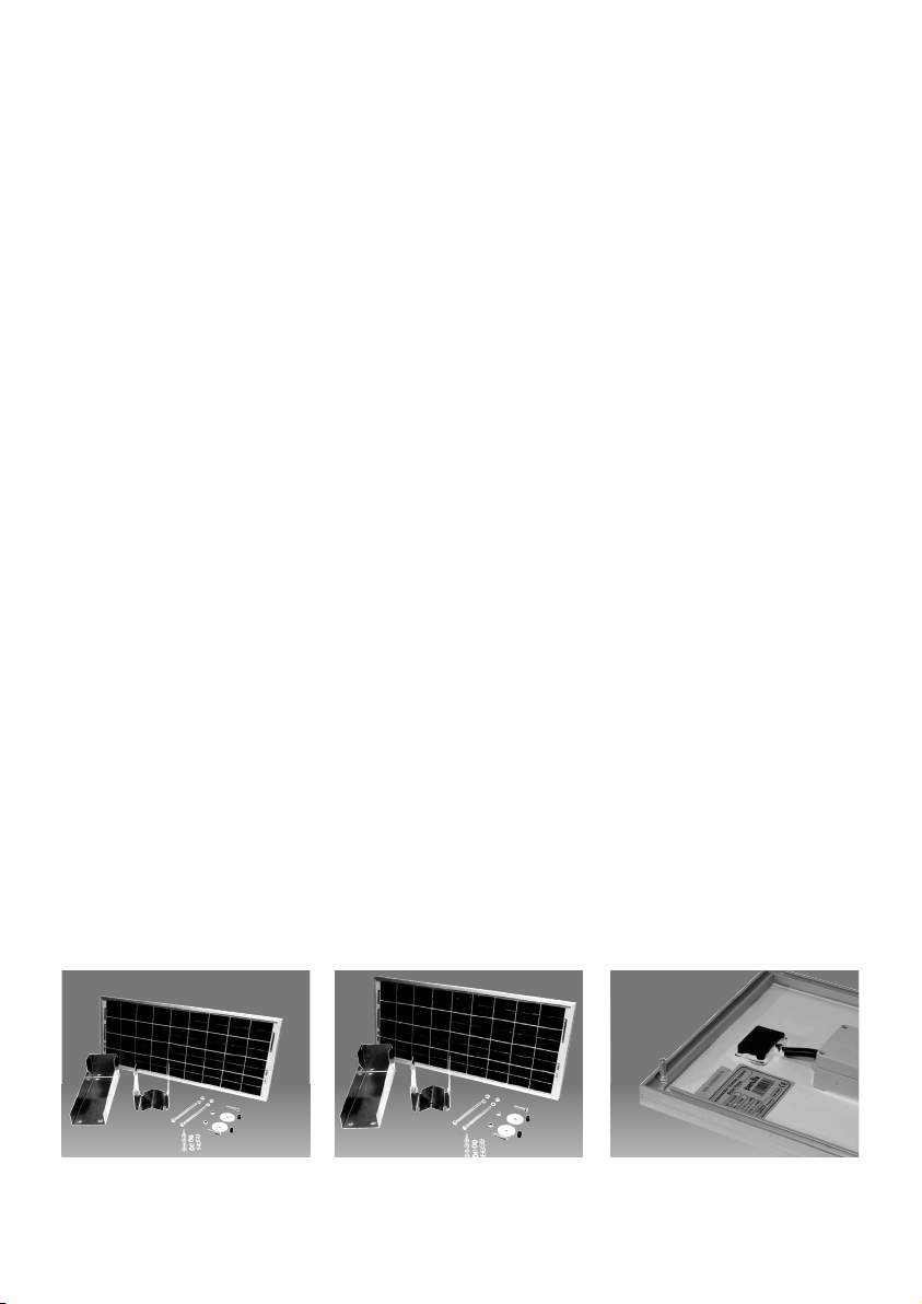
Abb. 15 Watt Modul: Überprüfen Sie
die gelieferte Ware auf Vollzähligkeit
anhand der Stückliste.
Abb. 25 Watt Modul: Überprüfen Sie
die gelieferte Ware auf Vollzähligkeit
anhand der Stückliste.
- 2 -
Schieben Sie je zwei Schrauben
(M6x16) oben und unten in das
Aluprofil des Solarmodulrahmens.
Richten Sie die Schrauben mittig auf
dem Solarmodul aus. Bitte Bohrabstände auf der Alu-Halterung beachten.
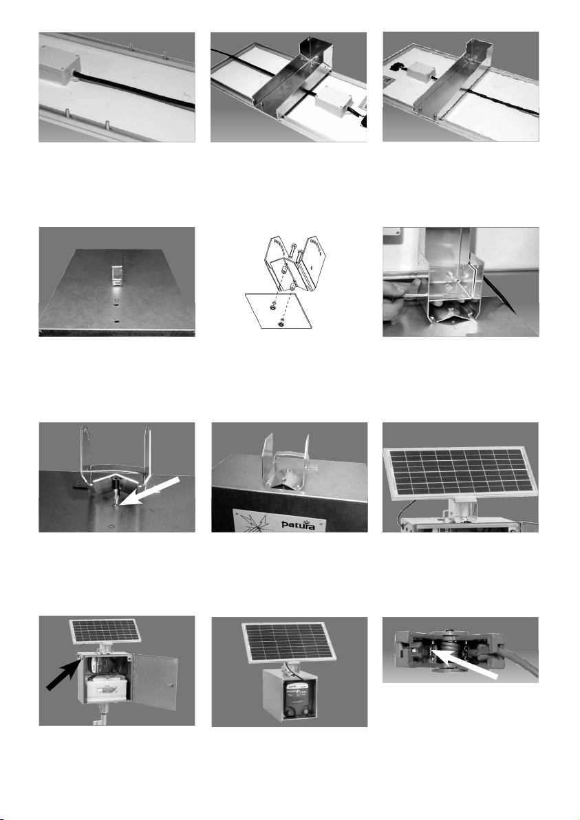
Montage auf Trageboxen
Abb. 15 Watt Modul: Schrauben Sie das
Oberteil des Solarmodulhalters auf das
Solarmodul.
Abb. 25 Watt Modul: Schrauben Sie das
Oberteil des Solarmodulhalters auf das
Solarmodul.
Richten Sie den Halter vorne, mittig auf
der Box aus, markieren die Bohr löcher
und bohren Sie 2 x 6,5 mm Löcher.
Schrauben Sie den Halter auf der Box
fest (Schraube M6x35, Distanzhülse,
Unterlegplatte, Stoppmutter M6).
Montage auf elektrifizierten Boxen
Richten Sie den Halter vorne, mittig auf
der Box aus, markieren die Bohr löcher
und bohren Sie 2 x 6,5 mm Löcher.
Schrauben Sie den Halter auf der E-Box
fest (Schraube M6x35, Distanzhülse,
Unterlegplatte, Stoppmutter M6).
Montage und Anschluß bei elektrifizierten Boxen und Trageboxen
Führen Sie das Solarmodul-Anschlußkabel durch die große Kabeltülle an der
Seite der E-Box hindurch.
-
Bei der offenen Tragebox führen Sie
das Anschlußkabel durch die Öffnung
von hinten an die Batterie.
-
3
Montieren Sie dann das vorbereitete
Solarmodul auf die Box.
Montieren Sie jetzt das vorbereitete
Solarmodul auf die Box.
Stecken Sie den Kabelschuh des roten
Kabels auf den freien Steckerplatz
der roten Batterieanschlußklemme.
Das schwarze Kabel ebenfalls wie
oben beschrieben an die schwarze
Batteriean schlußklemme anschließen.

Description
A condition de bien choisir leur dimension et de suivre les recommandations suivantes, les installations solaires
de PATURA sont étudiées pour assurer le bon fonctionnement de l’électrificateur sans aucune recharge du
printemps à l’automne, sans autre nécessité d’entretien. Il est même possible de prolonger le fonctionnement de
l’électrificateur jusqu’à l’hiver en diminuant la puissance de l’appareil.
Données techniques:
15 watts: type: SP 12/15/36. puissance max: 15 W – U charge: 17,3 V/l charge: 0,86 A -U circuit ouvert: 21,5 V/l court circuit: 0,96 A.
Dimensions (Lxl): 568 x 243 mm. Capacité minimum de la baterie ( non comprise dans l livraison): 80 Ah ( C100)
25 watts: type: SP 12/25/36. puissance max.:25 W - U charge: 17,3 V /l charge - 1,44 A - U circuit ouvert: 21,5 V/l court-circuit:
1,58 A. Dimensions ( Lxl): 627 x 360 mm. Capacité minimum de la batterie ( non comprise dans la livraison): 100 Ah (C100)
Contenu de la livraison:
1 x module solaire 15 W ou 25 W, avec régulateur de charge intégré et câble de raccordement
1 x support pour module solaire en aluminium, partie supérieure
1 x support pour module solaire aluminium, partie inférieure
4 x vis filetées M6x16 pour module solaire
4 x rondelles filetées M6 pour module solaire
6 x écrous filetés M6 (4 pour le module solaire, 2 pour le support)
2 x vis M6x100 pour le support sur le front de l’appareil
2 x rondelles M6x30 pour le support
2 x vis M6x30 pour le montage du support sur le boîtier.
2 x écrous indesserables filetes M6 pour pour le montage du support sur le boitier
2 x cylindres bloc pour le montage du support sur le boitier
1 x plat 100x100 pour le montage du support sur le boîtier
Outils nécessaires: 1 perceuse-visseuse, 1 foret 6,5 mm, 2 clés à cliquet 10 mm.
Recommandations d’utilisation:
•
Orienter le module plein sud, incliné à 45°C ; redresser éventuellement le module en hiver
et l’incliner davantage en été.
• Lemoduleperdconsidérablementdesapuissanceenprésenced’ombre
• Nettoyerrégulièrementlemodule
Installation du module solaire
Module 15 watts: vérifier si la livraison
est complète à l’aide de la liste des
pièces.
Module 25 watts: vérifier si la livraison
est complète à l’aide de la liste des
pièces.
- 4 -
Faire glisser dans le profil en alu du
cadre du module 2 vis ( M6x16) par le
haut et 2 autres ( M6x16) par le bas.

Positionner les vis au centre du module
en veillant à bien respecter les Intervalles des trous sur le support en alu.
Montage sur le boîtier de transport
Module 15 watts: Visser la partie
supérieure du support du module
solaire sur le module. (rondelle filetée
et écrou fileté M6)
Module 25 watts : Visser la partie
supérieure du support du module
solaire sur le module. (Rondelle filetée
et écrou fileté M6).
Positionner le support au milieu du
boîtier, marquer l’emplacement pour les
vis et percer des trous de 2 x 6,5 mm.
Visser fermement le support sur le boîtier
(vis M6x35, cylindre, plaque de support,
écrou M6).
Montage sur le boîtier antivol
Positionner le support au milieu du boîtier, marquer l’emplacement pour les
vis et percer des trous de 2 x 6,5 mm.
Visser fermement le support sur le boîtier antivol (vis M6x35, cylindre, plaque
de support, écrou M6).
Montage et raccordement sur boîtier électrique et boîtier de transport.
Faire passer le câble de raccordement
du panneau solaire par le passe-câble
sur le côté du boîtier antivol.
-
Faire passer le câble de raccordement
par l’ouverture qui se trouve derrière le
boîtier de transport.
-
5
Ensuite, monter le module solaire sur le
support sur le boîtier.
Monter à présent le module solaire sur
le support sur le boîtier.
Enfoncer la cosse du câble rouge dans
la fiche de la borne de raccordement
rouge de la batterie. Faire de même
avec le câble noir pour le relier à la
borne de raccordement noire de la
batterie.

Description
When correctly sized, PATURA solar installations are designed to run an electric fence installation
free, from spring through to autumn. If the energiser is switched down to a lower power level, this maintenance-free operation can be continued throughout the winter.
Technical data:
15 Watts: Type SP 12/15/36 • max. power output: 15 W • U
Dimensions (lxw): 568 x 243 mm • Minimum capacity of the battery (not included): 80 Ah (C100)
typical
: 17.3 V / I
: 0.86 A • U
typical
21.5 V / I
open
short
: 0.96 A
, maintenance
25 Watts: Type SP 12/25/36 • max. power output: 25 W • U
typical
: 17.3 V / I
: 1.44 A • U
typical
21.5 V / I
open
short
: 1.58 A
Dimensions (lxw): 627 x 360 mm • Minimum capacity of the battery (not included): 100 Ah (C100)
Scope of delivery
1 x Solar panel 15 W or 25 W, with integrated charge regulator and connecting cable
1 x Solar panel mounting bracket – top-frame (aluminium)
1 x Solar panel mounting bracket – bottom-frame (aluminium)
4 x Screw M6x16 for solar panel
4 x Spring washer M6 for solar panel
6x NutM6(4forsolarpanel,2formountingbracket)
2 x Screw M6x100 for mounting bracket
2 x Spring washer M6 for mounting bracket
2 x Screw M6x30 for mounting the bracket to the vandal-proof box
2 x Self-locking nut M6 for mounting the bracket to the vandal-proof box
1 x Support plate 100x100 for mounting the bracket to the vandal-proof box
2 x Spacer sleeves for mounting the bracket to the vandal-proof box
Necessarytools:Portablepowerdrill,drillbit6.5mm,2flatwrenches10mm(wrenchsize)
Application information:
•
Facing due south, at a 45° horizontal angle (year-round operation); for winter operation
increase the angle, for summer operation decrease the angle
• Avoidshadewhichreducespoweroutputsignificantly
• Thesolarpanelneedstobecleanedregularly
Installation: Solar panel
Picture of 15 W panel: check the parts
list to verify that all parts were shipped.
Picture of 25 W panel: check the parts
list to verify that all parts were shipped.
- 6 -
Insert two screws (M6x16) each at the
top and on the bottom of the aluminium frame of the solar panel.

Align the screws in the centre of the
solar panel. Please note the drill hole
spacing on the aluminum mounting
bracket.
Mounting to carry boxes
Picture of 15 W panel: Screw the top
part of the solar panel mounting bracket to the solar panel.
Picture of 25 W panel: Screw the top
part of the solar panel mounting bracket to the solar panel.
Align the mounting bracket antered on
the top front of the box, mark the drill
holes and drill 2 x 6.5 mm holes.
Screw the mounting bracket to the vandalproof box (screw M6x35, spacer sleeve,
support plate, self-locking nut M6)
Mounting to vandal-proof boxes
Align the mounting bracket antered on
the top front of the box, mark the drill
holes and drill 2 x 6.5 mm holes.
Screw the mounting bracket to the vandalproof box (screw M6x35, spacer sleeve,
support plate, self-locking nut M6)
Mounting and connection to vandal-proof boxes and carry boxes
Guide the solar panel connecting cable
through the large cable support sleeve
on the side of the vandal-proof box.
-
Guide the connecting cable through the
back opening of the open carry box to
the battery.
-
7
Mount the pre-assembled solar panel to
the vandal-proof box.
Mount the pre-assembled solar panel to
the vandal-proof box.
Insert the cable socket of the red cable
in the free plug position of the red
battery clip. The black cable should be
connected to the black battery clip as
described above.

130422
PATURA KG
63925Laudenbach•Germany
•Mainblick1
+49(0)9372-94740
☎
Fax +49(0)9372-947429
- 8 -
info@patura.com
www.patura.com
 Loading...