

Patty-O-Matic Protege Owner's Manual

Patty-O-Matic, Inc. ®
The World’s Finest Food Machines
Model Protégé
Owner’s Manual
Revised April 2006
Route 547 P.O. Box 404 Farmingdale NJ,07727
Tel: (732) 938-2757 Fax: (732) 938-5809
Toll Free in USA: 877-938-5244
Congratulations on the purchase of your new Model Protégé Patty
Molding Machine from Patty-O-Matic, Inc! The Model Protégé will form,
interleave paper between, and stack food patties. This machine is designed
for easy operation and cleaning. Please become familiar with this manual
and your machine will give you years of service.
The Model Protégé is shipped to you in at least two cartons which
contain the patty machine, feed tray complete with mold plate guard, parts
box, receiving table, and this manual. If you purchased your machine with
any other accessories, such as a mobile table or patty paper, these items may
be in a separate carton. The parts box that comes with the machine should
include a bottle of machine lubricant, a speed driver, samples of patty paper,
and a spare parts kit.
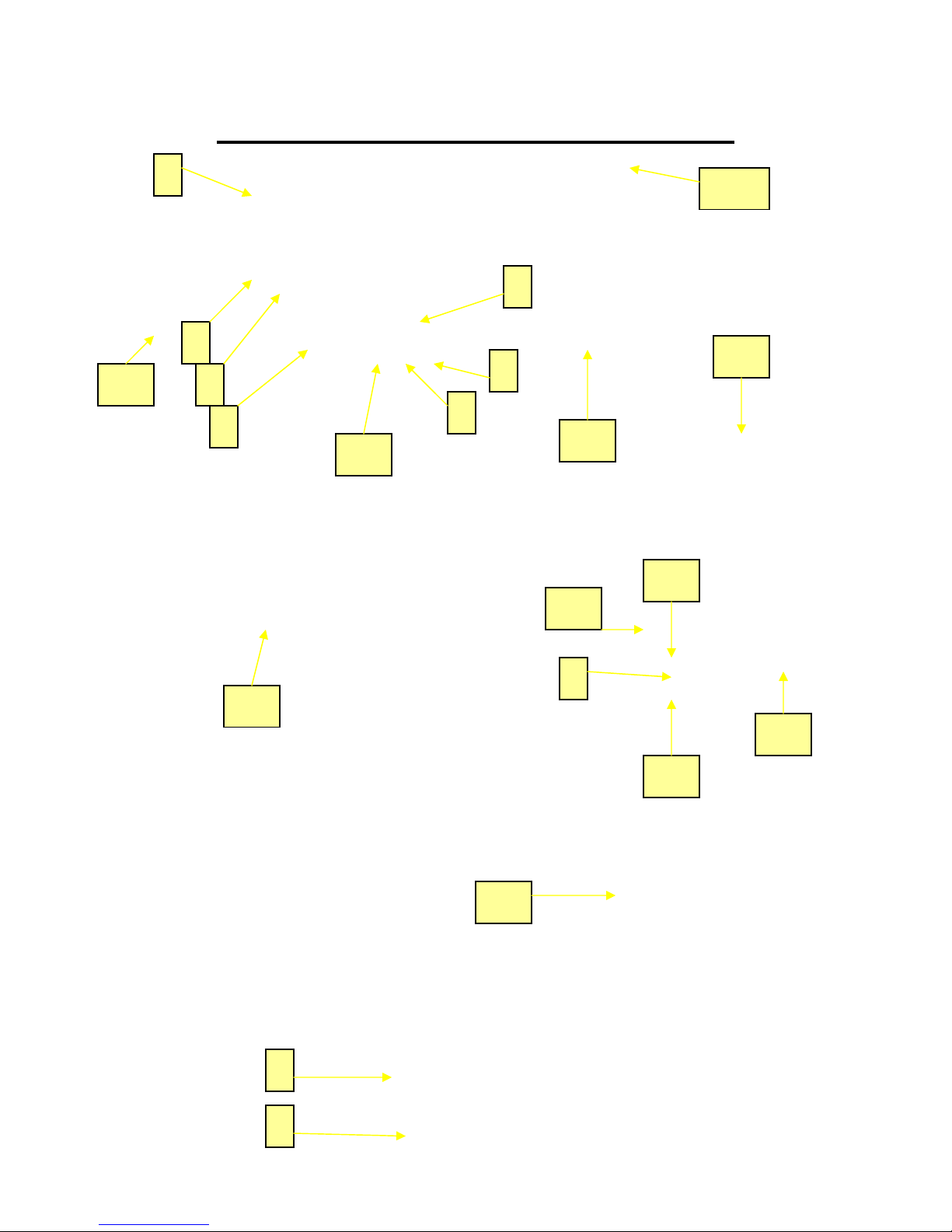
Your machine is equipped with one interlock. This interlock is
located on the top left side of the machine. The Feed Tray with the attached
Mold Plate Guard must be installed on the machine to engage the interlock
on top of the machine.
Installing the Feed Tray with
Interlock
Tower
2
Hopper
the attached Mold Plate
Guard
Place tube of Feed Tray over the
Hopper. Line up the plunger that
is located on the underside of the
feed tray with the Tower Sleeve.
This will push down on the
interlock Tower located inside
the Tower Sleeve of the
Machine.
DO NOT ATTEMPT TO RUN THIS
MACHINE WITHOUT THE FEED
TRAY AND THE MOLD PLATE
GUARD IN THEIR PLACE!!
FAILURE TO DO SO COULD
RESULT IN SERIOUS BODILY
INJURIES!!
Feed Tray
Plunger
located
here
Feed Tray Guard
Mold Plate
Guard

3
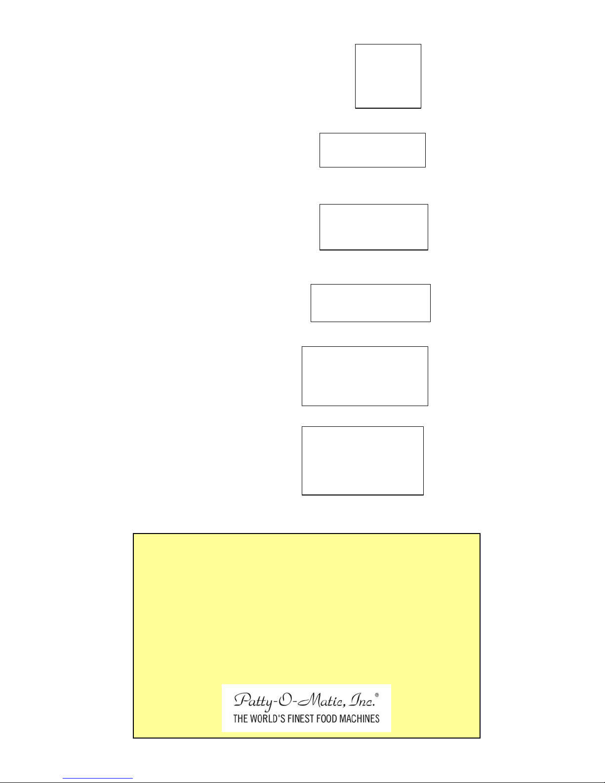
Please become familiar with some of the parts
Pressure
Hopper
Mold Plate Assembly Underside View
of your machine prior to operation.
Feeder
Mold Plate
Protégé
Back Drive
T-Knob
Hole
Feeder
Washer
Meat Stop
Mixer
Collar
T-Knob
Feeder Top
View
Feeder Side
Transition Plate Protégé Mold Plate Assembly Side View
Ring Pin Pressure Plate
Feed Tray Guard and Mold Plate Guard are installed for
your safety. Do not tamper with them in any way!
Feed Tray Guard
Feed Tray with
Mold Plate Guard
Protégé Knock Out
Cup Assembly
17
4
Proper Label Location for a Model Protégé
1
2
3
9
4
10
7
8
13
16
18
10
14
11
12
5
14
15
6
2

5
Item # Description Part #
1. Danger Tag 514-09
2. Warning Orange 514-02
3. Patty-O-Matic 514-08
4. Warning 514-06
5. Danger Label 1 514-03
6. Danger Label 2 514-00
7. Serial Tag 514-15
8. Store Tool 514-14
9. Warning Manual 514-01
10. Danger on/off 514-05
11. Do Not Pressure Wash 514-04
12. Keep Hands 514-07
13. Pro Warning and Always 514-13
14. Danger Keep Clear 514-16
15. Pro Position 514-11
16. Pro Caution TI Plate 514-10
17. Pro Risk 514-17
18. Pro If Sign is Visible 514-14
These Labels are available through the
factory, at no charge. Contact the factory for
replacements if something is to happen to the
originals. Please contact the factory for
further information:
Toll Free in the U.S.A. 877-938-5244
Outside the U.S.A. 732-938-2757
6

7
Always Disconnect Machine From its Power Source Before Cleaning or Adjusting!
Proper Procedure for Operating a Model Protégé
When the Model Protégé is fully assembled with all guards secured in their proper
place, put product in the Feed Tray. Push the product through the holes in the Feed Tray
Guard into the hopper opening. DO NOT PUT HANDS OR FINGERS, OR
FOREIGN OBJECTS, SUCH AS STOMPERS OR PLUNGERS INTO THE
HOPPER. THERE ARE NO STOMPERS OR PLUNGERS NEEDED WHEN
USING THIS UNIT, THEREFORE NONE ARE SUPPLIED. After you allow
product to drop into hopper turn the machine on by moving the On/Off switch down
towards the on position. The machine may need to cycle a few times to prime the
machine with product. As patties are being formed continue to push product through the
holes and under the Feed Tray Guard. Patty paper may be added to the machine as
needed. The machine can hold up to 1 inch of paper at a time.
As the Mold Plate moves back and forth to form patties, a thin coating of product
may accumulate over its surface. This coating may also accumulate on the edges of the
Knock Out Cup or on the front of the hopper and spacer plate. This accumulation does
occur on all molding machines. It is nothing to be concerned with. There are certain
machine settings that may lessen this accumulation.
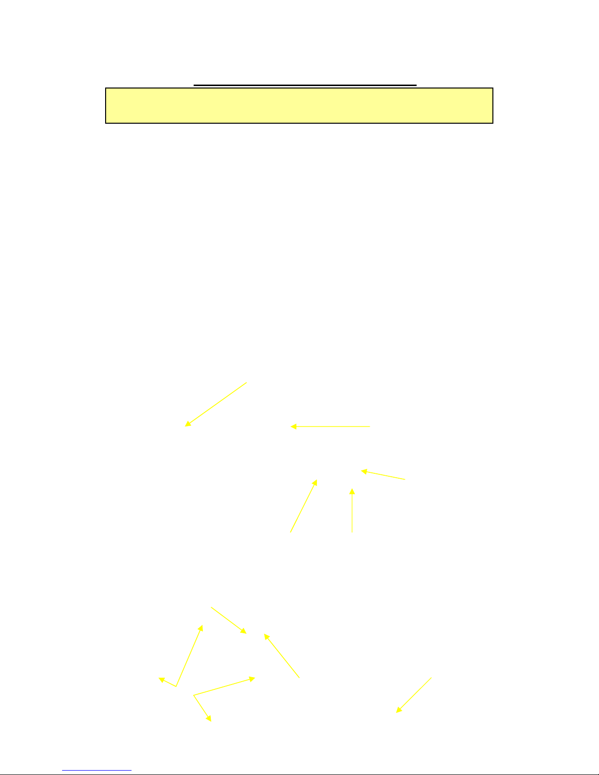
Setting the Ring Pin Pressure Plate for your Patty Size
The Purpose of the Pressure Plate is to entrap the amount of product necessary to form your patty.
This part is also used in controlling the firmness of your patty. With the Pressure Plate set
correctly you will in turn have:
- less leakage, oozing, and coating of parts
- less kneading of your product
- and less strain on your machine.
-----------------------------------------------------------
picture. This will allow the Pressure Plate to move all the way into the hopper and stop into the
welded stud which is the maximum setting.
ounce hole.
If you would like to have a tightly packed patty, move the ring pin to a higher than
recommended setting for that particular weight.
THESE ARE ONLY RECOMMENDED SETTINGS. A VARIETY OF CIRCUMSTANCES
ggggggggggggggggggggggg
MAY CALL FOR YOU TO INSERT THE RING PIN IN A DIFFERENT LOCATION.
If your patty weight is 8 ounces, keep the ring pin in the storage hole as described in the
If your patty is 4 ounces remove the ring pin from the storage hole and place it in the 4
If you patty weight is to be 6 ounces, place the ring pin in the 6 ounce hole.
1 - Ring Pin in storage hole
2 - 2 ounce hole
3 - 3 ounce hole
4 - 4 ounce hole
5 - 5ounce hole
6 - 6 ounce hole
7 - 7 ounce hole
8 - 8 ounce welded stop
1
8
6
3
5
7
2
4
8
Changing Your Machine’s Mold Plate
Always disconnect the machine from its power source
First remove the T-Knob from the Back Drive of the Mold Plate, then pull the
Mold Plate out from the rear of the machine. If you prefer, remove the Mold Plate from
the machine without removing the T-Knob from the Back Drive. Simply unhook
Connecting Arm from the T-Knob and slide the Mold Plate from the rear of the machine.
before attempting to change any of the machines component parts.
When changing the Mold Plate always use the corresponding Transition Plate.
The thickness fraction stamped on the Transition Plate should match the fraction stamped
on the front right corner of the Mold Plate. For example: if your Mold Plate is stamped
“4F ½” then the Transition Plate should be stamped “1/2” The Transition Plate is
removed by removing the four Hopper hold down Bolts and the Feeder Hold Down Bolt.
Once these bolts are removed lift the Feeder from the Hopper and the hopper from the
machine. Once the Hopper and Feeder are removed lift the Transition Plate and repl ace it
with the new one. Make sure the fraction that is stamped on the plate is facing the front
of the machine. After putting the new Transition Plate in place replace the Hopper and
Feeder, then install the same thickness mold plate mold plate. Be sure to replace the
Knock Out Cup to match the new Mold Plate size.
Knock Out
Cup
Transition
Plate
Back Drive
Connecting
Arm
Connecting Arm
T-Knob
Feeder Bolt
Transition Plate Shown
in the Up Position
Feeder
Hopper
Bolt Holes
Thickness
Stamp
 Loading...