

Patty-O-Matic PR12 Owner's Manual
Model PR12
Owner’s Manual
Revised October 2019
Patty-O-Matic Inc.
Route 547 P.O. Box 404 Farmingdale NJ,07727
(732)938-2757 Toll Free in USA: 877-938-5244
www.pattyomatic.com
info@pattyomatic.com
E469483
NSF/ANSI 8
E475191

2
Table of Contents
• Introduction to Your Machine Page 3
• Installing Machine on Riser Platform Page 3
• Installing Rear Machine Guard Feed Tray Page 3
• Accessories Equipped with the Model PR12 Page 4
• Parts to Become Familiar with Page 5
• Label Location and Description Pages 6&7
• Operating Procedure Page 8
• Setting Ring Pin Pressure Plate Page 8
• Changing Mold Plate and Transition Plate Page 9
• Proper Disassembly for Cleaning and Sanitizing Page 10&11
• Installing Patty Paper Page 12
• Points of Lubrication Page 12
Parts Representation
• Feed Tray Assembly Page 13
• Mold Plate Guard Assembly Page 13
• Knock Out Cup Assembly Page 13
• Hopper Assembly Page 14
• Feeder Assembly Page 14
• Assembled Machine Views Page 15
• Paper Interleaver Assembly Page 16
• Ring Pin Pressure Plate Page 17
• Mold Plate Assembly Page 17
• Assembled Hopper and Feeder Page 17
• Electrical Switches Page 18
• Tower Assembly Page 19
• Main Shaft Assembly Page 20
• Crank Housing Assembly Page 21
• Motor To Main Shaft Page 22
• Knock Out Cam Assembly Page 23
• Knock Out Shaft and Lever Assembly Page 23
• Main Motor Side View Page 24
• Mold Plate Guide Rails Page 24
• Main Shaft Outside Machine View Page 24
• Wiring Diagram Page 25
• Warranty Information Page 26
• Important Information Guide Page 27
• Notes Page 28
3
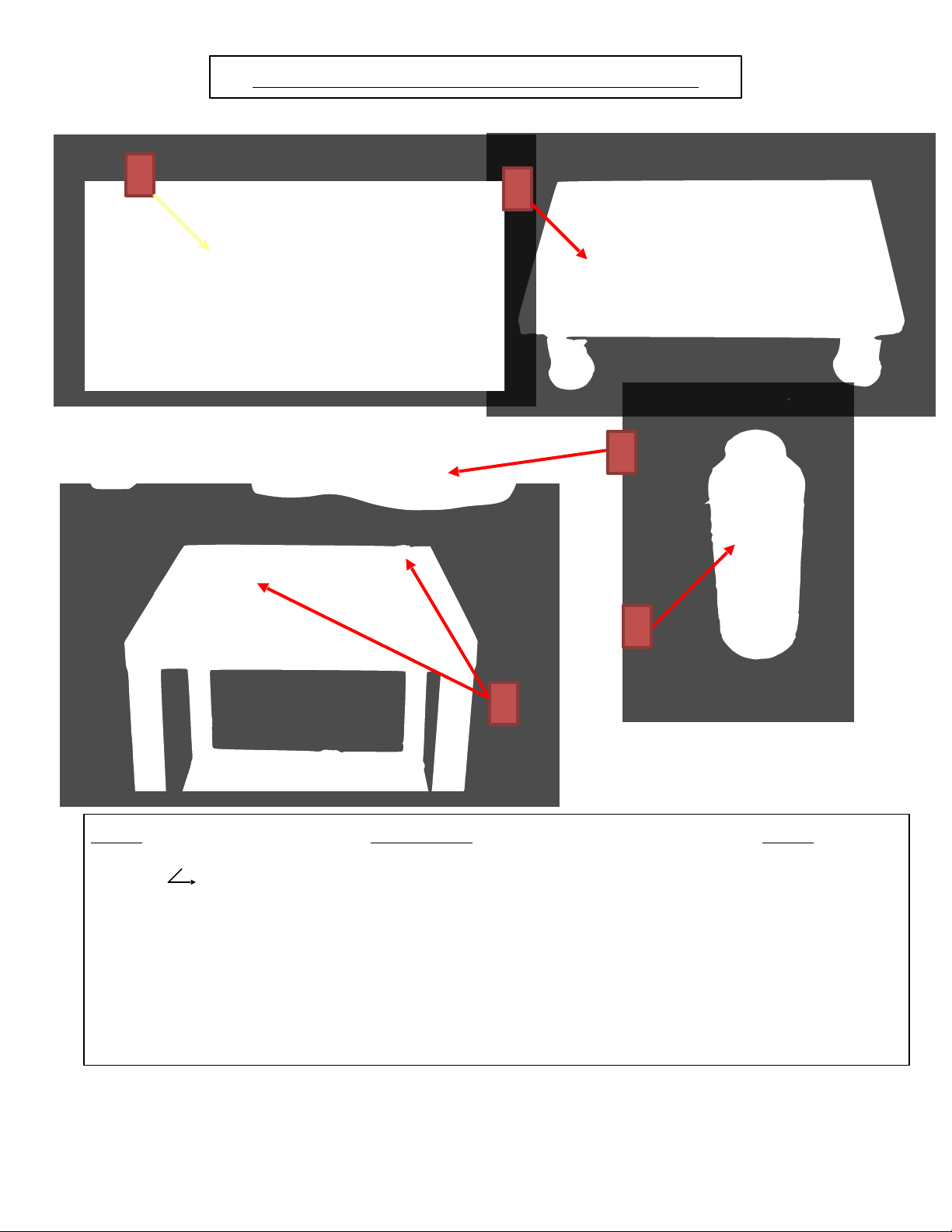
Installing Rear Machine Guard
Loosen the two bolts, one on the
Hopper and one on the rear of the
machine. Place Rear Machine
Guard under the washers located
under the bolt heads. Tighten bolts
using the provided Speed Driver.
To activate the interlock, slide push
rod into the plunger, inside the
keylatch, and turn rod to the right.
This will lock the push rod in place
and activate the interlock.
Installing the Feed Tray
Place stainless steel tube of Feed
Tray over the Hopper. Make sure
the Plunger on the bottom of Feed
Tray depresses the Tower Stem
inside the Tower Sleeve.
Installing Machine onto Riser
Platform
Place machine on the riser platform
making sure the 4 legs of the
machine go into the 4 leg wells on
the Riser Platform. The Picture
shown shows the front view of the
Riser Platform.
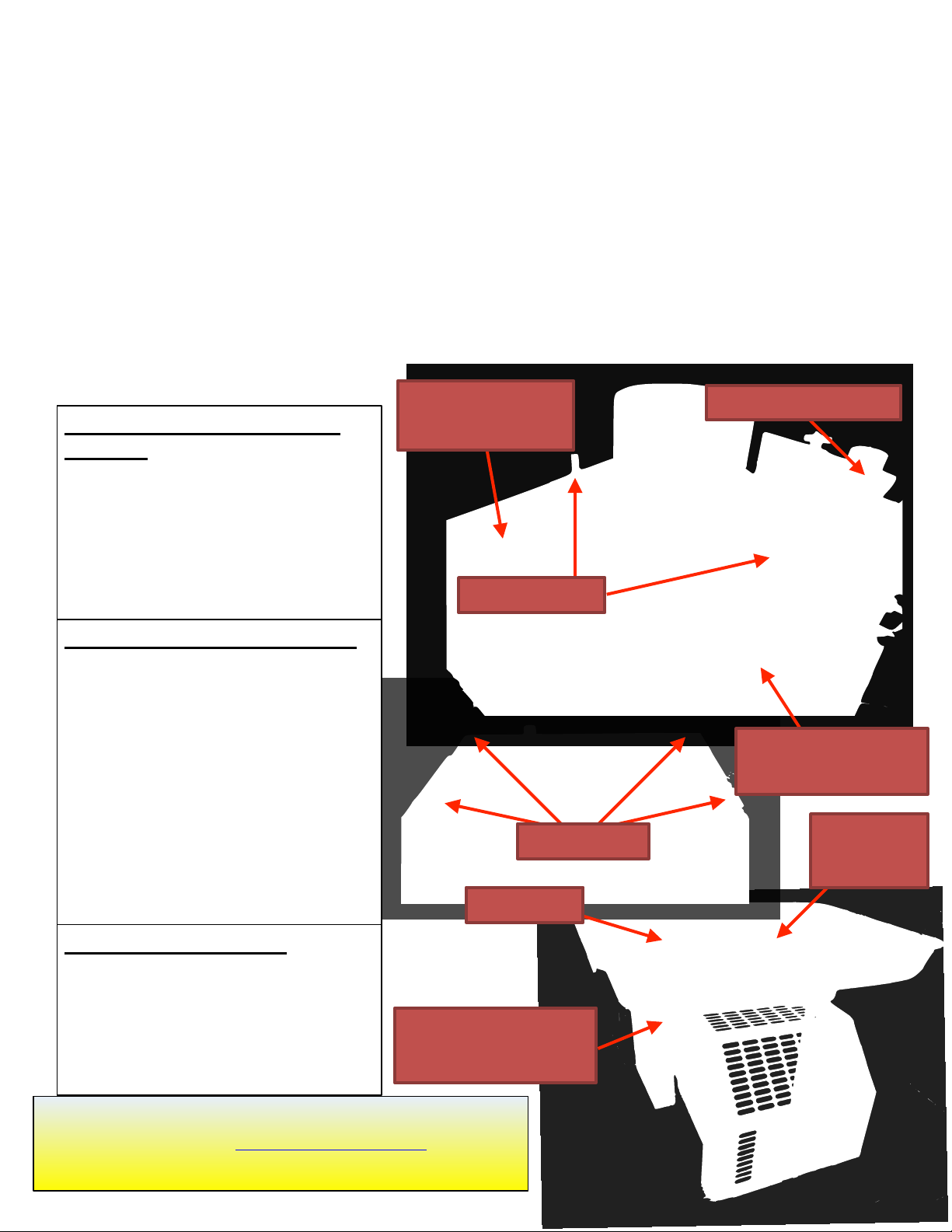
Thank you and congratulations on the purchase of your new Model PR12 Patty Molding Machine from
Patty-O-Matic, Inc! The Model PR12 will form, interleave paper between, and stack patties. This machine is
designed for easy operation and cleaning. Please become familiar with this manual and your machine will
give you many years of productive service.
The Model PR12 is shipped to you in at least two cartons which contain the patty machine, feed tray
complete with mold plate guard, rear machine guard, spare parts box, riser platform, and this manual. If you
purchased your machine with any other accessories, such as a mobile table or patty paper, these items may be
in a separate carton.
Your machine is equipped with two interlocks. One is located on the top of the machine and one is
located on the back of the machine. The Rear Machine Guard must be installed properly to engage the
interlock on the back of the machine and the Feed Tray must be installed on top of the Hopper to engage the
interlock on top of the machine.
For Additional Information or to view our Operational
Videos please visit www.PattyOMatic.com or call
732-938-2757
Feed Tray
Feed Tray
Guard
Push Rod &
Round Keylatch
Guard Bolts
Interlock Tower
Rear Machine
Guard
Leg Wells
Plunger located
behind guard
4
Accessories Equipped with the Model PM18
1
2
Item# Description Part #
1 Spare Parts Box 655
Holds Spare Parts, Patty Paper Sample, Machine Lubricant, Speed Driver, and
Locator Rings c/w instructions
2 Receiving Table 609-6
3 Speed Driver 544
4 8 Ounce Bottle of Machine Lubricant and Cleaner 600
5 Gallon of Machine Lubricant(Separate Order Only) 600A
6 Machine Locator Rings 610-2
6
3
4
5
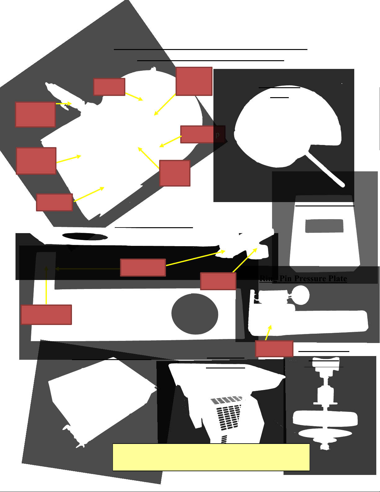
Please become familiar with some of the parts
of your machine prior to operating machine
Transition Plate
Mold Plate Assembly
T-Knob Hole
Ring Pin Pressure Plate
Knock Out Cup
Assembly
Refer to Page 12
Hopper
Please become familiar with some of the parts
of your machine prior to operation
Meat Stop
Mixer
Collar
Feeder Top
View
Feeder
Washer
Feeder
Pressure
Plate
Chamber
Lid
T-Knob
Back Drive
Rear Machine Guard
Feed Tray
c/w Guard
Feed Tray Guard and Mold Plate Guard, are installed for your
safety. Do not tamper with them in any way!
Ring Pin
6
4
8
9
2
3
1
7
2
10
5
11
9
12
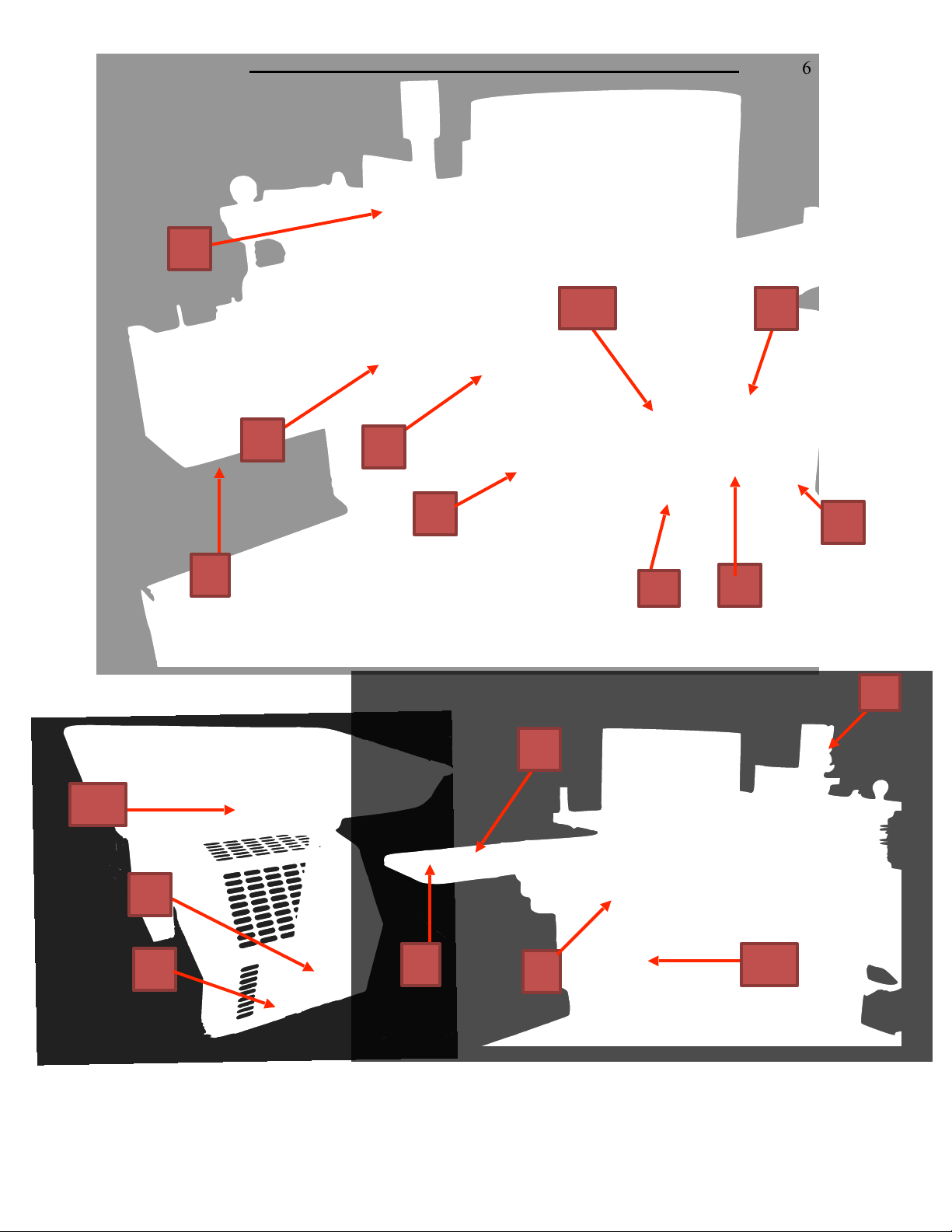
Proper Label Location for a Model PR12
6
1
13
15
14
7
1. Danger Label 3 514-09a
2. Warning Orange 514-02
3. Patty-O-Matic 514-08
4. Safety instructions 514-06
5. Danger Label 2 514-00
6. Serial Tag For UL Machines 514-15UL
7. Store Tool 514-14
8. Warning Manual 514-01
9. Danger on/off 514-05
10. Do Not Pressure Wash 514-04
11. Unplug Machine 514-07
12. Made in USA 514-19
Item # Description Part#
13. Pro Position 514-11
14. Pro Risk 514-17
15. Danger Keep Clear 514-16
8
Adjusting the Paper Attachment for different size paper
1. The Paper Pin Bracket can be adjusted for
different paper by loosening the bolts. To avoid improper
paper feeding, the correct setting is to have the leading
edge of the paper in line with the front edge of the roller.
2. The Paper Attachment can also move for further
adjustment by loosening the set bolt and sliding the
attachment. The set collar(not shown) located on the
support shaft may need to be loosened to move the Paper
Attachment toward the mold plate.
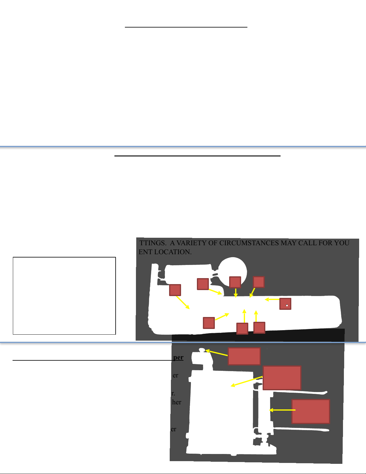
Setting the Ring Pin Pressure Plate for your Patty Size
The Purpose of the Pressure Plate is to entrap the amount of product necessary to form your patty and to control
the firmness of your patty. With the Pressure Plate set correctly you will in turn have less leakage, oozing, over working
of your product, and less strain on your machine.
If your patty weight is 8 ounces, keep the ring pin in the storage hole as described in the picture. This will allow
the Pressure Plate to move all the way into the Hopper and stop on the welded stop. This setting traps the most product
and is the maximum volume setting.
If your patty weight is 4 ounces, place the ring pin in the 4 ounce hole.
If your patty weight is 6 ounces, place the ring pin in the 6 ounce hole.
If you would like to have a tightly packed patty, move the ring pin to a higher than recommended setting.
THESE ARE ONLY RECOMMENDED SETTINGS. A VARIETY OF CIRCUMSTANCES MAY CALL FOR YOU
TO INSERT THE RING PIN IN A DIFFERENT LOCATION.
2
1
5
6
1 - Ring Pin in storage hole
2 - 2 ounce hole
3 - 3 ounce hole
4 - 4 ounce hole
5 - 5ounce hole
6 - 6 ounce hole
7 - 7 ounce hole
8 - 8 ounce welded stop
1
8
7
Proper Procedure for Operating a PR12
When the Model PR12 is fully assembled with all guards secured in their proper place, put product to be molded
in the Feed Tray. Push the product through the holes in the Feed Tray Guard, or under the Feed Tray guard and into the
Hopper. DO NOT PUT HANDS OR FINGERS, OR FOREIGN OBJECTS, SUCH AS STOMPERS OR
PLUNGERS INTO THE HOPPER. THERE ARE NO STOMPERS OR PLUNGERS NECESSARY WHEN
USING THIS UNIT, THEREFORE NONE ARE SUPPLIED. After you allow product to drop into the Hopper turn
the machine on by moving the On/Off switch down towards the on position. The machine may need to cycle a few times
to prime the machine with product. As patties are being formed, continue to push product through the holes and under
the Feed Tray Guard. Patty paper may be added to the machine as needed. The machine can hold up to 3/4 inch of paper
at a time, but no more.
As the Mold Plate moves back and forth to form patties, a thin coating of product may accumulate over its
surface, the Knock Out Cup, or on the front of the Hopper and Transition Plate. This accumulation does occur on all
molding machines an it is nothing to be concerned with. Do Not attempt to clean this accumulation while machine is
plugged in. There are certain machine settings that may lessen this accumulation.
3
Set Bolt
Paper Pin
Bracket
Roller
Front Edge
9
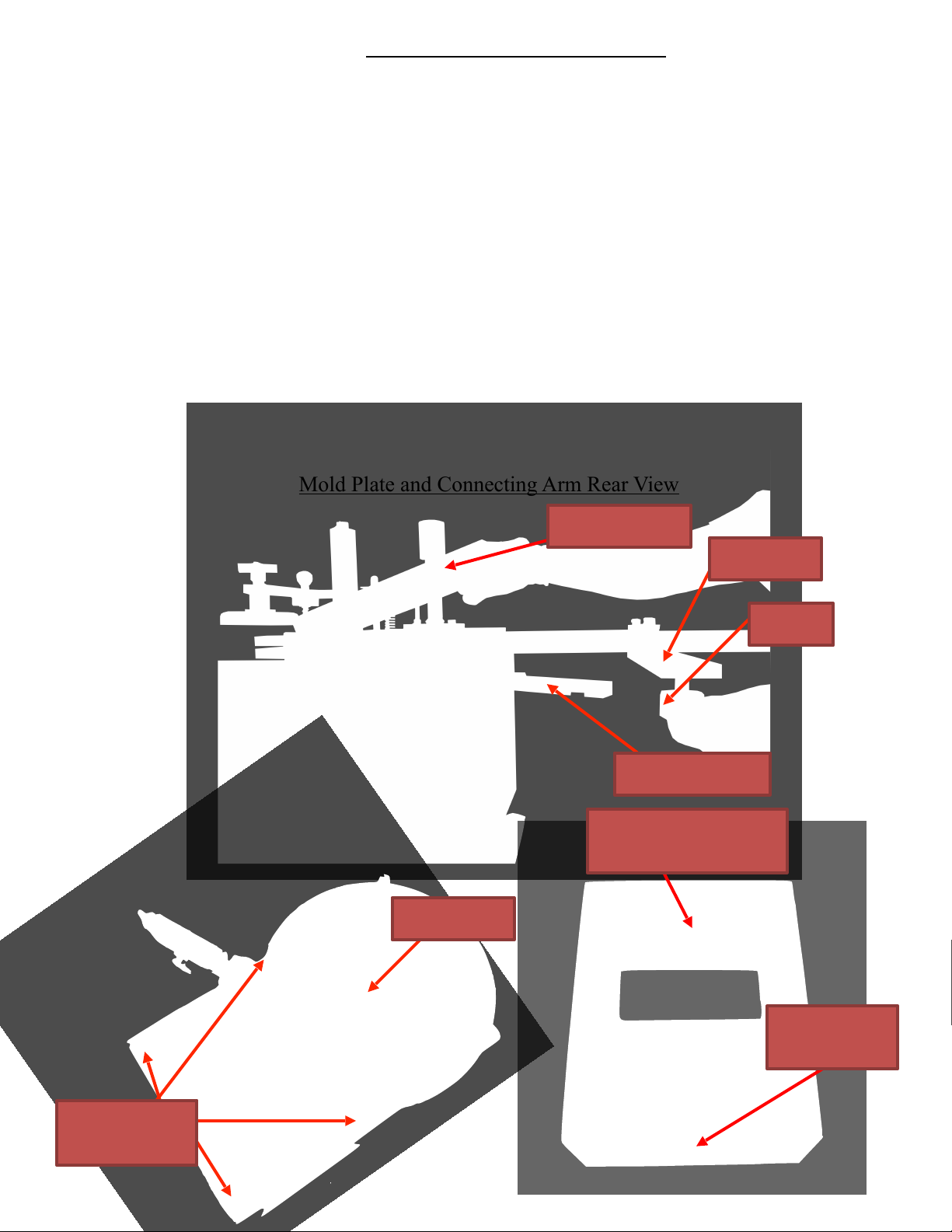
Mold Plate and Connecting Arm Rear View
Feeder Bolt
Transition Plate
Changing Your Machine’s Mold Plate
Always disconnect the machine from its power source
before attempting to change or clean any of the machines component parts.
First remove the T-Knob from the Back Drive of the Mold Plate, then pull the Mold Plate out from
the rear of the machine. If you prefer, remove the Mold Plate from the machine without removing the TKnob from the Back Drive. Simply unhook Connecting Arm from the T-Knob and slide the Mold Plate from
the rear of the machine.
When changing the Mold Plate always use the corresponding Transition Plate. The thickness fraction
stamped on the Transition Plate should match the fraction stamped on the front right corner of the Mold
Plate. For example: if your Mold Plate is stamped “4F 1⁄2” then the Transition Plate should be stamped “1/2”
The Transition Plate is removed by removing the four Hopper hold down Bolts and the Feeder Hold Down
Bolt. Once these bolts are removed lift the Feeder from the Hopper and the hopper from the machine. Once
the Hopper and Feeder are removed lift the Transition Plate and replace it with a different size. Make sure
the fraction that is stamped on the Transition plate is facing the front of the machine. After putting the new
Transition Plate in place replace the Hopper and Feeder, then install the same thickness mold plate. Be sure
to replace the Knock Out Cup to match the new Mold Plate size.
Transition Plate
Shown in Up Position
Back Drive
T-Knob
Hopper Bolt
Holes
Thickness
Fraction Stamp
Connecting Arm
 Loading...