

Patton electronics 2800, OnSite 2835, OnSite 2821, OnSite 2803/K, OnSite 2803/T Quick Start Manual
Page 1

OnSite™ 2800 Series
VPN Routers
Quick Start Guide
Part Number: 07M2800-QS, Rev. E
Revised: February 22, 2012
Sales Office: +1 (301) 975-1000
Technical Support: +1 (301) 975-1007
E-mail: support@patton.com
WWW: www.patton.com
Page 2

WARNING
• The OnSite contains no user serviceable parts. The equipment shall be
returned to Patton Electronics for repairs, or repaired by qualified
service personnel.
• Mains Voltage: Line voltages are present when the power cord is connected. The mains outlet shall be within 10 feet (3 meters) of the
device, shall be easily accessible, and protected by a circuit breaker.
• For AC powered units, ensure that the power cable used meets all
applicable standards for the country in which it is to be installed, and
that it is connected to a wall outlet which has earth ground.
• Hazardous network voltages are present in WAN ports, regardless of
whether power to the OnSite is ON or OFF. To avoid electric shock,
use caution when near WAN ports. When detaching the cables, detach
the end away from the OnSite first.
• Do not work on the system or connect or disconnect cables during
periods of lightning activity.
• For units with an external power adapter, the adapter shall be a
listed Limited Power Source.
1.0 Powering up the OnSite
The interconnecting cables shall be acceptable for external use and shall be rated for
the proper application with respect to voltage, current, anticipated temperature, flammability, and mechanical serviceability.
CAUTION
Your OnSite comes with one of the following power supply options and power accessories:
•
External AC (desktop) adaptors—power cord and AC power adaptor are included
•
Internal AC power supply—power cord is included
•
Internal DC power supply—no power accessories are included
1.1 Models with external AC adaptors
1. Connect the AC power cord female plug to the AC adaptor provided with your OnSite router.
2. Connect the AC adaptor barrel type connector to the OnSite router.
3. Connect the AC power cord male plug to an AC power outlet (100–240 VAC).
1.2 Models with internal AC power supply
1. Connect the AC power cord female plug directly to the OnSite AC connector.
2. Connect the AC power cord male plug to an AC power outlet (120–240 VAC).
2 OnSite 2800 Quick Start Guide
Page 3
1.3 Models with internal DC power supply
1. Strip insulation 1/4-inch from the wires connecting the power source to the OnSite.
2. Connect the ground terminal from the power source with to the E terminal on the OnSite.
3. Connect the negative (-) terminal from the power source with to the (-) terminal on the OnSite.
4. Connect the positive (+) terminal from the power source with to the (+) terminal on the OnSite.
The PWR LED blinks as the OnSite is powering up. When the PWR LED stops blinking and remains lit, the OnSite
is ready for user configuration.
2.0 Setting the IP address
2.1 Default IP configuration
The factory default IP settings are as follows:
•
LAN port(s) (green, ETH 0/1): IP address: 192.168.1.1, netmask: 255.255.255.0
•
WAN port (red, ETH 0/0): IP address and netmask: DHCP client
•
A DHCP server with address space 192.168.1.10–192.168.1.99 (netmask: 255.255.255.0) is running on the
LAN ports
•
Both Ethernet ports are pre-configured and active
If these addresses conflict or do not match with your network they must be changed. Contact your network
administrator if you are not sure which IP address to use in your installation.
2.2 Connecting to the PC and logging in
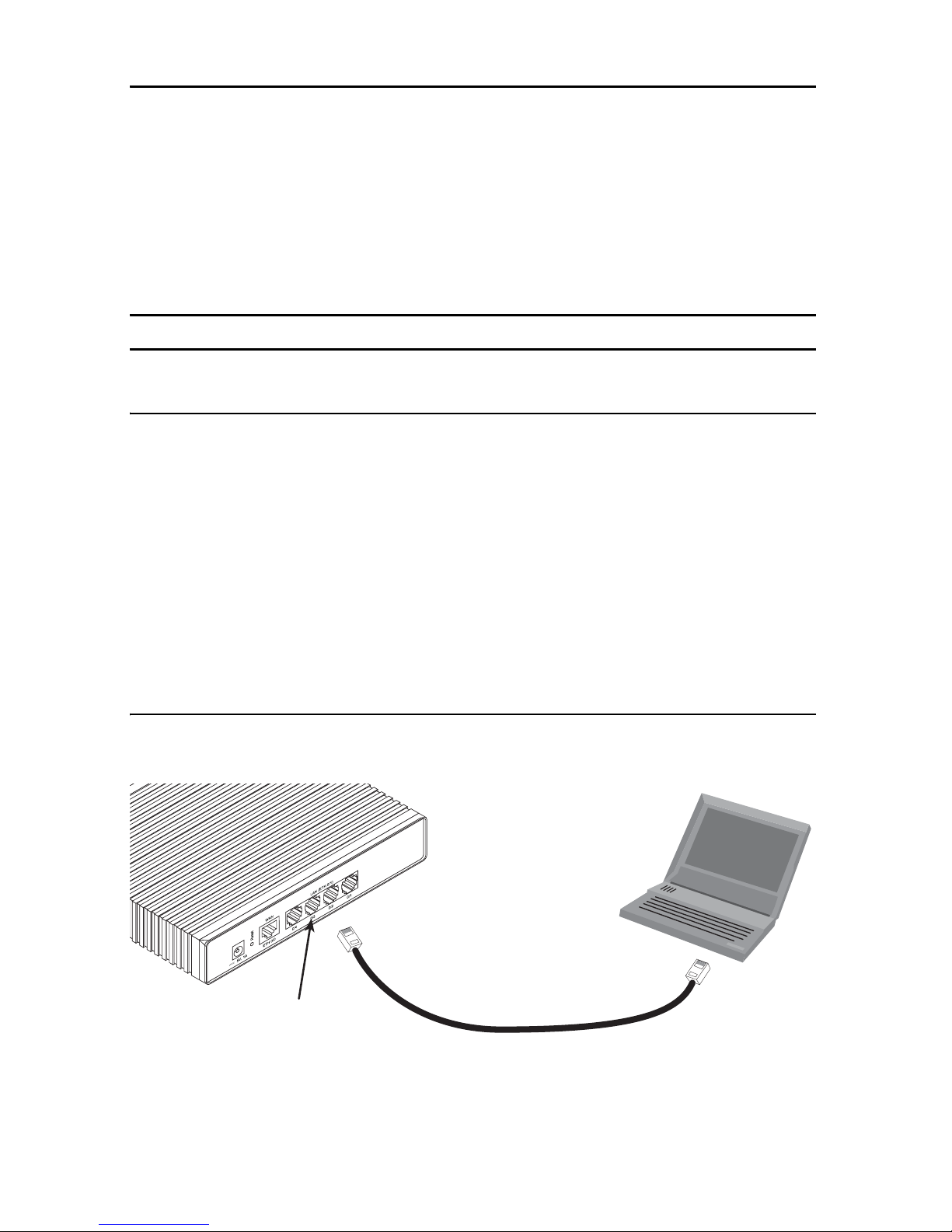
1. To access the OnSite configuration, connect a PC with an Ethernet port to one of the LAN ports (green)
(see figure 1). Use the black Ethernet cable included with your OnSite for this purpose.
PC
(DHCP, for example:
192.168.1.10/24)
IPLink 2800
192.168.1.1/24
Ethernet port
Connect to Ethernet LAN
ports 0/1Ð0/4
2. Set your PC’s TCP/IP configuration to DHCP to automatically receive an IP address from the OnSite.
OnSite 2800 Quick Start Guide 3
Figure 1. Connecting to the PC’s ENET port
Page 4

3. Open a Telnet connection to the default LAN IP address of the OnSite (192.168.1.1).
Use the name administrator after the login prompt and simply press the Enter key after the
password prompt.
login:administrator
password:
2803/K/EUI>
Note The prompt includes the model number of your OnSite (2803/K/EUI in the example above) of the WAN
(ETH 0/0) port.
4. After you have successfully logged in you are in the operator execution mode, indicated by '>' as com-
mand line prompt. With the commands enable and configure you enter the configuration mode.
2803/K/EUI>enable
2803/K/EUI#configure
2803/K/EUI(cfg)#
2.3 Changing the IP address
When you connect the WAN interface eth 0/0, the WAN port operates as a DHCP client and acquires its IP
address/netmask from the WAN network’s DHCP server. However you can change the configuration of the Eth
0/0 from DHCP client to a fixed IP address as follows. In this example, we assume a private network since the IP
address changes to 172.16.1.100 with netmask of 255.255.255.0.
1. Select the context IP mode to configure an IP interface.
2803/K/EUI(cfg)#context ip router
2803/K/EUI(ctx-ip)[router]#
2. Set your IP address and network mask on the WAN IP interface eth0. (Contact your network administra-
tor if you are not sure what IP address to set.)
2803/K/EUI(ctx-ip)[router]#interface eth0
2803/K/EUI(if-ip)[eth0]#ipaddress 172.16.1.100 255.255.255.0
172.16.1.100(if-ip)[eth0]#
3. Store this modified configuration and make it your new start-up configuration. On the next start-up the
system will come up using the modified configuration.
172.16.1.100(if-ip)[eth0]#copy running-config startup-config
172.16.1.100(if-ip)[eth0]#
Now the OnSite can be connected to your IP network. Remember that if Eth 0/0 remains as a DHCP client, it gets
the IP address from your IP network’s DHCP server. If you changed the IP address as we showed in this example,
it assumes your IP network (actually Ethernet segment) is on the same subnet, 192.16.1.0/24.
4 OnSite 2800 Quick Start Guide
Page 5

3.0 Connecting to the network
Connect the OnSite to the IP network (see figure 2) and do any remaining configuration from a PC connected to
the same Ethernet segment.
Host with Telnet client
192.168.1.10/24
192.168.1.1/24
172.16.1.100/24
IP Network
Figure 2. Connecting to a host
Host with TFTP server
(static IP address)
172.16.1.X/24
You can check the connection with the ping command. For example shown in figure 2, you would ping
172.16.1.100 from a PC on the IP network.
You may now start to configure the OnSite using the CLI commands. For a detailed description of the CLI refer to
the OnSite 2800 Series User Manual available online at www.patton.com/manuals/2800.pdf.
4.0 Connecting the OnSite serial port
If your OnSite is equipped with a serial WAN port, connect it to the appropriate DCE. The OnSite 2800 Series is
available with the following serial interfaces:
•
V.35 (DB-25)—Model 2835
•
X.21 (DB-15)—Model 2821
•
E1 (RJ48C or dual coaxial connectors)—Model 2803/K
•
T1 (RJ48C)—Model 2803/T
For the V.35 and X.21 serial ports, do the following to connect the serial cable to the OnSite:
1. Attach the male connector of the serial cable to the female serial connector on the router.
2. Attach the other end of the cable to the serial connector on local serial modem or multiplexer device.
OnSite 2800 Quick Start Guide 5
Page 6

Note The router’s V.35 interface is wired as a DCE. No DTE configuration is possible. If you are directly con-
necting the router’s V.35 interface to third-party equipment that cannot be configured as a DTE, you
must use a tail-circuit cable. You can purchase a tail-circuit cable from a datacom-supply vendor. A tailcircuit cable will cross-over the necessary V.35 signals so that the two DCE interfaces can communicate.
Note The router’s X.21 interface is wired as a DCE. No DTE configuration is possible. The router’s X.21 inter-
face requires a cable with a male DB-15 connector.
For the OnSite’s T1/E1 WAN port, connect to an E1 service as follows:
1. Your incoming E1 connection will be either a twisted pair cable terminated with an RJ48C plug or two
coaxial cables. (T1 is RJ48C only.)
— If an RJ48C plug, plug the cable into the RJ48C connector between the two coaxial connectors on
the rear of the OnSite.
— If two coaxial cables, plug the coaxial cables into the RX and TX connectors on the rear of the
OnSite. The RX is an input and the TX is an output.
2. The T1/E1 port default is disabled. Enable the T1/E1 port.
2803/K/EUI(if-ip)[eth0]#exit
2803/K/EUI(ctx-ip)[router]#exit
2803/K/EUI(cfg)#port e1t1 0 0
2803/K/EUI(prt-e1t1)[0/0]#no shutdown
2803/K/EUI(prt-e1t1)[0/0]#show port e1t1 0 0
...
The configuration of the enabled T1/E1 port is displayed. The defaults for the E1 are Master clocking, Line Code
HDB3, Framing CRC4, Impedance 120 Ohms. This is for connecting to the RJ48C.
For modifying the T1/E1 port configuration, consult the OnSite Software Configuration Guide on the Patton website: www.patton.com/manuals.
5.0 Additional information
For detailed information about configuring and operating guidance, set up procedures and troubleshooting,
refer to the OnSite 2800 Series User Manual available online at www.patton.com/manuals/2800.pdf.
6 OnSite 2800 Quick Start Guide
Page 7

6.0 EC Declaration of Conformity
Product Description: OnSite 2802, OnSite 2803, OnSite 2805, OnSite 2821, OnSite 2823, and OnSite 2835.
We certify that the apparatus identified above conforms to the requirements of Council Directive 1999/5/EC on
the approximation of the laws of the member states relating to Radio and Telecommunication Terminal Equipment and the mutual recognition of their conformity.
The safety advice in the documentation accompanying this product shall be obeyed. The conformity to the above
directive is indicated by the CE sign on the device.
The safety advises in the documentation accompanying the products shall be obeyed.
The conformity to the above directive is indicated by the CE sign on the device.
The signed Declaration of Conformity can be downloaded from www.patton.com/certifications/.
OnSite 2800 Quick Start Guide 7
Page 8

Copyright statement
Copyright © 2012, Patton Electronics Company. All rights reserved.
The information in this document is subject to change without notice. Patton Electronics assumes no
liability for errors that may appear in this document.
Trademarks statement
The term OnSite is a trademark of Patton Electronics Company. All other trademarks presented in this document
are the property of their respective owners.
Patton support headquarters in the USA
•
Online support: Available at www.patton.com
•
E-mail support: E-mail sent to support@patton.com will be answered within 1 business day
•
Telephone support: Standard telephone support is available five days a week—from 8:00 am to
5:00 pm EST (1300 to 2200 UTC/GMT)—by calling +1 (301) 975-1007
•
Support via VoIP: Contact Patton free of charge by using a VoIP ISP phone to call sip:support@patton.com
•
Fax: +1 (253) 663-5693
Alternate Patton support for Europe, Middle East, and Africa (EMEA)
•
Telephone support: Standard telephone support is available five days a week—from 8:00 am to
5:00 pm CET (0900 to 1800 UTC/GMT)—by calling +41 (0)31 985 25 55
•
Fax: +41 (0)31 985 25 26
Note For additional service and support information, refer to the “Contacting Patton for assistance” chapter
of the OnSite 2800 Series User Manual available online at www.patton.com/manuals/
2800.pdf.
Warranty, Compliance Information
For warranty, trademark and compliance information, refer to the OnSite 2800 Series User Manual available
online at www.patton.com/manuals/2800.pdf.
Ultimate disposal of this equipment must be handled according to all applicable
national laws and regulations.
CAUTION
8 OnSite 2800 Quick Start Guide
 Loading...