

Page 1
Model 1001MC
NetLink™
SNMP Management Card
Operations Guide
Sales Office: +1 (301) 975-1000
Technical Support: +1 (301) 975-1007
E-mail: support@patton.com
WWW: www.patton.com
Document Number: 022021U Rev. F
Part Number: 07M1001MC
Revised: May 19, 2008
Page 2

Patton Electronics Company, Inc.
7622 Rickenbacker Drive
Gaithersburg, MD 20879 USA
tel: +1 (301) 975-1000
fax: +1 (301) 869-9293
support: +1 (301) 975-1007
url: www.patton.com
e-mail: support@patton.com
Copyright Statement
Copyright © 2008, Patton Electronics Company. All rights reserved.
Trademark Statement
The terms NetLink , KiloModem , and MegaLink-I are trademarks of Patton Electronics
Company. All other trademarks presented in this document are the property of their
respective owners.
Notices
The information contained in this document is not designed or intended for use as
critical components in human life-support systems, equipment used in hazardous
environments, or nuclear control systems. Patton Electronics Company disclaims
any express or implied warranty of fitness for such uses.
The information in this document is subject to change without notice. Patton Electronics assumes no liability for errors that may appear in this document.
Any software described in this document is furnished under license and may be used
or copied only in accordance with the terms of such license.
Page 3

Contents
About this guide .....................................................................................................................................................6
Audience................................................................................................................................................................. 6
Structure................................................................................................................................................................. 6
Typographical conventions used in this document.................................................................................................. 7
Additional References ..............................................................................................................................................8
Technical support....................................................................................................................................................8
1 Introduction.................................................................................................................................................. 10
Introduction..........................................................................................................................................................11
Model 1001MC management overview.................................................................................................................14
2 Hardware installation.................................................................................................................................... 15
Introduction..........................................................................................................................................................17
Installing the Model 1001MC into the rack chassis ...............................................................................................18
Installing NetLink modem cards ...........................................................................................................................19
Installing the power supplies..................................................................................................................................31
Verifying 1001MC functioning.............................................................................................................................31
Connecting the cables............................................................................................................................................32
LED indicators ......................................................................................................................................................34
Where to go next...................................................................................................................................................35
3 Getting started............................................................................................................................................... 36
Introduction..........................................................................................................................................................37
Booting the Model 1001MC.................................................................................................................................37
Installing the Model 1001MC RS-232 daisy-chain port cable ...............................................................................39
Introduction to the internal HTTP/HTML management pages ............................................................................41
Saving HTTP/HTML object changes....................................................................................................................42
Where to go next…...............................................................................................................................................46
4 Model 1092ARC management ...................................................................................................................... 47
Introduction..........................................................................................................................................................49
Configuration and management ............................................................................................................................49
Modem Information page MIB variables description.............................................................................................57
Model 1092 Configuration Slot page MIB variables description............................................................................61
Model 1092 Configuration—Next Configuration page MIB variables description ................................................63
Slot Configuration page MIB variables description................................................................................................65
5 Model 1094ARC management ...................................................................................................................... 67
Introduction..........................................................................................................................................................69
Configuration and management ............................................................................................................................69
Modem Information page MIB variables description.............................................................................................78
Model 1094 Configuration Slot page MIB variables description............................................................................81
Model 1094 Configuration—Next Configuration page MIB variables description ................................................84
Slot Configuration page MIB variables description................................................................................................86
3
Page 4

4
Model 1001MC Operations Guide
Contents
Using the Download page to upgrade 1094ARC software .....................................................................................87
6 Model 1095RC management......................................................................................................................... 89
Introduction..........................................................................................................................................................92
Configuration and management ............................................................................................................................92
Modem Information page MIB variables description...........................................................................................101
Model 1095 Configuration Slot page MIB variables description..........................................................................104
Model 1095 Configuration—Next Configuration page MIB variables description ..............................................107
Slot Configuration page MIB variables description..............................................................................................110
Using the Download page to upgrade 1095RC software......................................................................................111
Creating and modifying global configuration templates.......................................................................................113
7 Model 2701RC management....................................................................................................................... 129
Introduction........................................................................................................................................................132
Configuration and management ..........................................................................................................................132
Modem Information Rack X page MIB variables description...............................................................................140
Model 2701RC Configuration Slot X page MIB variables description.................................................................143
Model 2701 Configuration page MIB variables description.................................................................................149
Slot Configuration page MIB variables description..............................................................................................153
Creating and modifying global configuration templates.......................................................................................155
8 Model 2707RC management....................................................................................................................... 167
Introduction........................................................................................................................................................169
Configuration and management ..........................................................................................................................169
Modem Information page MIB variables description...........................................................................................177
Model 2707RC Configuration Slot page MIB variables description ....................................................................181
Model 2707RC Configuration—Configuration page MIB variables description .................................................183
Slot Configuration page MIB variables description..............................................................................................185
9 Model 3088RC management....................................................................................................................... 187
Introduction........................................................................................................................................................190
Configuration and management ..........................................................................................................................190
Modem Information Rack X page MIB variables description...............................................................................198
Model 3088RC Configuration Slot X page MIB variables description.................................................................201
Model 3088RC Configuration page MIB variables description ...........................................................................206
Slot Configuration page MIB variables description..............................................................................................209
Creating and modifying global configuration templates.......................................................................................211
10 HTTP/HTML web page reference............................................................................................................... 220
Introduction........................................................................................................................................................224
HOME................................................................................................................................................................228
About 1001MC...................................................................................................................................................231
Import Export .....................................................................................................................................................233
System Level Information....................................................................................................................................235
Modem Information Rack X ...............................................................................................................................239
Slot Configuration...............................................................................................................................................243
System Information.............................................................................................................................................246
Page 5

5
Model 1001MC Operations Guide
Contents
Download............................................................................................................................................................249
System Log..........................................................................................................................................................251
System Log—Modify ..........................................................................................................................................252
System Log—Volatile Memory............................................................................................................................256
System Log—Non-Volatile Memory ...................................................................................................................257
SNMP.................................................................................................................................................................258
System Config .....................................................................................................................................................259
Help ....................................................................................................................................................................275
11 Troubleshooting and maintenance.............................................................................................................. 276
Introduction........................................................................................................................................................277
Troubleshooting the 1001MC rack card..............................................................................................................277
Troubleshooting network malfunctions...............................................................................................................278
1001MC test mode diagnostics ...........................................................................................................................282
Maintenance........................................................................................................................................................284
12 Contacting Patton for assistance ................................................................................................................. 286
Introduction........................................................................................................................................................287
Contact information............................................................................................................................................287
Warranty Service and Returned Merchandise Authorizations (RMAs).................................................................287
Page 6

About this guide
This guide describes installing and operating a Patton Electronics 1001MC NetLink™ SNMP Management
Card. This section describes the following:
• Who should use this guide (see “Audience”)
• How this document is organized (see “Structure”)
• Typographical conventions and terms used in this guide (see “Typographical conventions used in this docu-
ment” on page 7)
Audience
This guide is intended for use by qualified systems administrators and network engineers to configure and
manage the Patton Electronics Model 1001MC and NetLink™ modems. Knowledge of basic networking concepts is assumed
Structure
This guide contains the following chapters:
• Chapter 1 (on page 10) introduces the Model 1001MC and provides an overview of the management window
• Chapter 2 (on page 15) describes how to install the Model 1001MC
• Chapter 3 (on page 36) describes how to boot the Model 1001MC, install cables, set up the address range for
NetLink modems, log into the HTTP/HTML administration pages, and save HTTP/HTML object changes
• Chapter 4 (on page 47) describes how to manage a 1092ARC NetLink modem
• Chapter 5 (on page 67) describes how to manage a 1094ARC NetLink modem
• Chapter 6 (on page 89) describes how to manage a 1095RC NetLink modem
• Chapter 7 (on page 129) describes how to manage a 2701RC NetLink modem
• Chapter 8 (on page 167) describes how to manage a 2707RC NetLink modem
• Chapter 9 (on page 187) describes how to manage a 3088RC G.SHDSL NTU rack card
• Chapter 10 (on page 220) is the 1001MC-NMS HTTP/HTML web page reference
• Chapter 11 (on page 276) contains troubleshooting and maintenance information
• Chapter 12 (on page 286) contains information on contacting Patton technical support for assistance
6
Page 7
Model 1001MC Operations Guide
About this guide
Typographical conventions used in this document
This section describes the typographical conventions and terms used in this guide.
General conventions
The procedures described in this manual use the following text conventions:
Table 1. Text conventions
Convention
Garamond blue type
Futura bold type Indicates the names of menu bar options.
Italicized Futura type
Futura type Indicates the names of fields or windows.
Garamond bold type Indicates the names of command buttons that execute an action.
< > Angle brackets indicate function and keyboard keys, such as <SHIFT>,
Are you ready? All system messages and prompts appear in the Courier font as the
% dir *.* Bold Courier font indicates where the operator must type a response or
Indicates a cross-reference hyperlink that points to a figure, graphic,
table, or section heading. Clicking on the hyperlink jumps you to the reference. When you have finished reviewing the reference, click on the
Go to Previous View button
toolbar to return to your starting point.
Indicates the names of options on pull-down menus.
<CTRL>, <C>, and so on.
system would display them.
command
Meaning
in the Adobe® Acrobat® Reader
7
Page 8

8
Model 1001MC Operations Guide
Mouse conventions
The following conventions are used when describing mouse actions:
Table 2. Mouse conventions
Convention Meaning
Left mouse button
Right mouse button This button refers the secondary or rightmost mouse button (unless you have
Point This word means to move the mouse in such a way that the tip of the pointing
Click Means to quickly press and release the left or right mouse button (as instructed in
Drag This word means to point the arrow and then hold down the left or right mouse but-
This button refers to the primary or leftmost mouse button (unless you have
changed the default configuration).
changed the default configuration)
arrow on the screen ends up resting at the desired location.
the procedure). Make sure you do not move the mouse pointer while clicking a
mouse button. Double-click means to press and release the same mouse button two
times quickly
ton (as instructed in the procedure) as you move the mouse to a new location.
When you have moved the mouse pointer to the desired location, you can release
the mouse button.
About this guide
Additional References
The Patton Electronics website (www.patton.com) provides 1001MC and NetLink modem application notes,
which includes FAQ, startup notes, and test setups.
RFCs
Use a web browser to find online copies of the following requests for comments (RFC) documents:
• RFC 1643, Definitions of Managed Objects for the Ethernet-like Interface Types
• RFC 1155, Structure and Identification of Management Information for TCP/IP-based Internets
• RFC 1213, Management Information Base for Network Management of TCP/IP-based Internets: MIB-II
• RFC 1389, RIP Version 2 MIB Extension
• RFC 1643, Definitions of Managed Objects for the Ethernet-like Interface Types
Technical support
Patton Electronics offers a wide array of free technical services. If you have questions about any of our other
products we recommend you begin your search for answers by using our technical knowledge base. Here, we
have gathered together many of the more commonly asked questions and compiled them into a searchable
database to help you quickly solve your problems.
• Online support—available at www.patton.com .
• E-mail support—e-mail sent to support@patton.com will be answered within 1 business day
• Telephone support—standard telephone support is available Monday through Friday, from 8:00 A.M. to
5:00 P.M. EST (8:00 to 17:00 UTC-5), Monday through Friday by calling +1 (301) 975-1007
Additional References
Page 9

9
About this guide
Model 1001MC Operations Guide
Service
All warranty and non-warranty repairs must be returned freight prepaid and insured to Patton Electronics. All
returns must have a Return Materials Authorization number on the outside of the shipping container. This
number may be obtained from Patton Electronics Technical Services at:
• Tel: +1 (301) 975-1007
• E-mail: support@patton.com
• URL: http://www.patton.com
Note
Packages received without an RMA number will not be accepted.
Technical support
Page 10

Chapter 1
Chapter contents
Introduction..........................................................................................................................................................11
Model 1001MC management overview.................................................................................................................14
Introduction
10
Page 11
11
Model 1001MC Operations Guide
1 • Introduction
Introduction
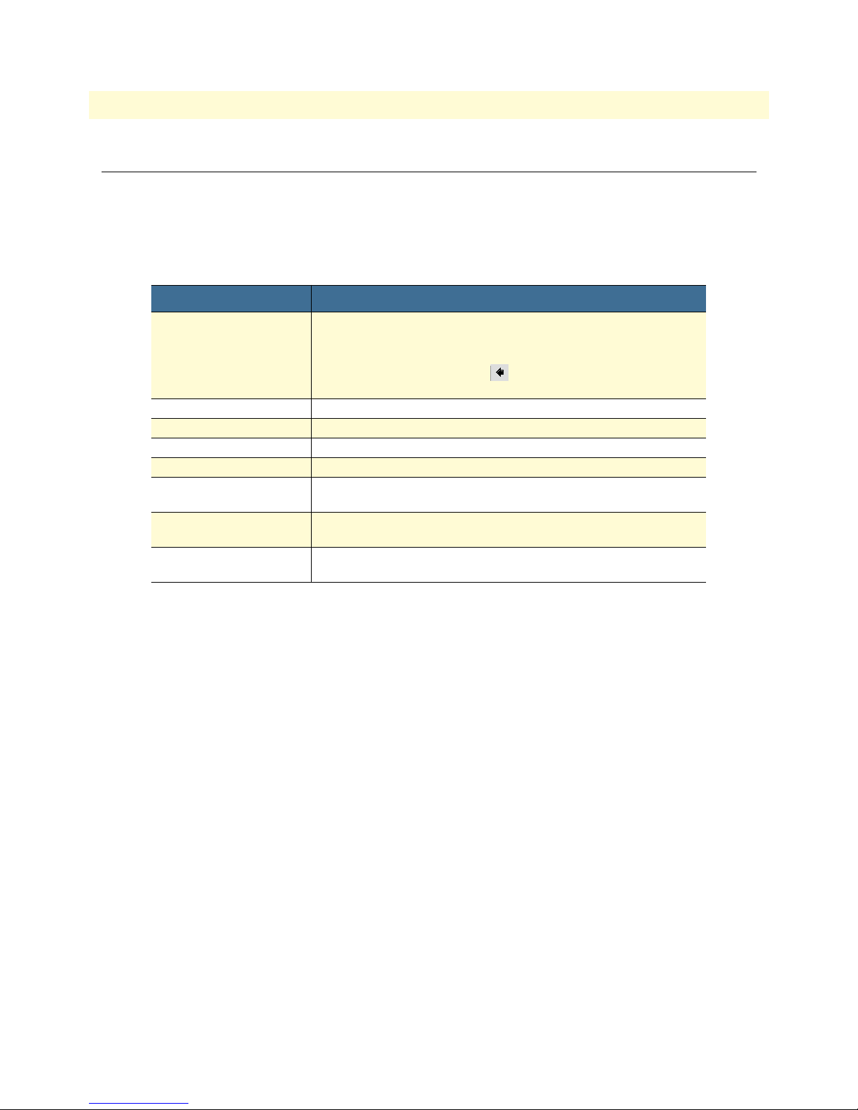
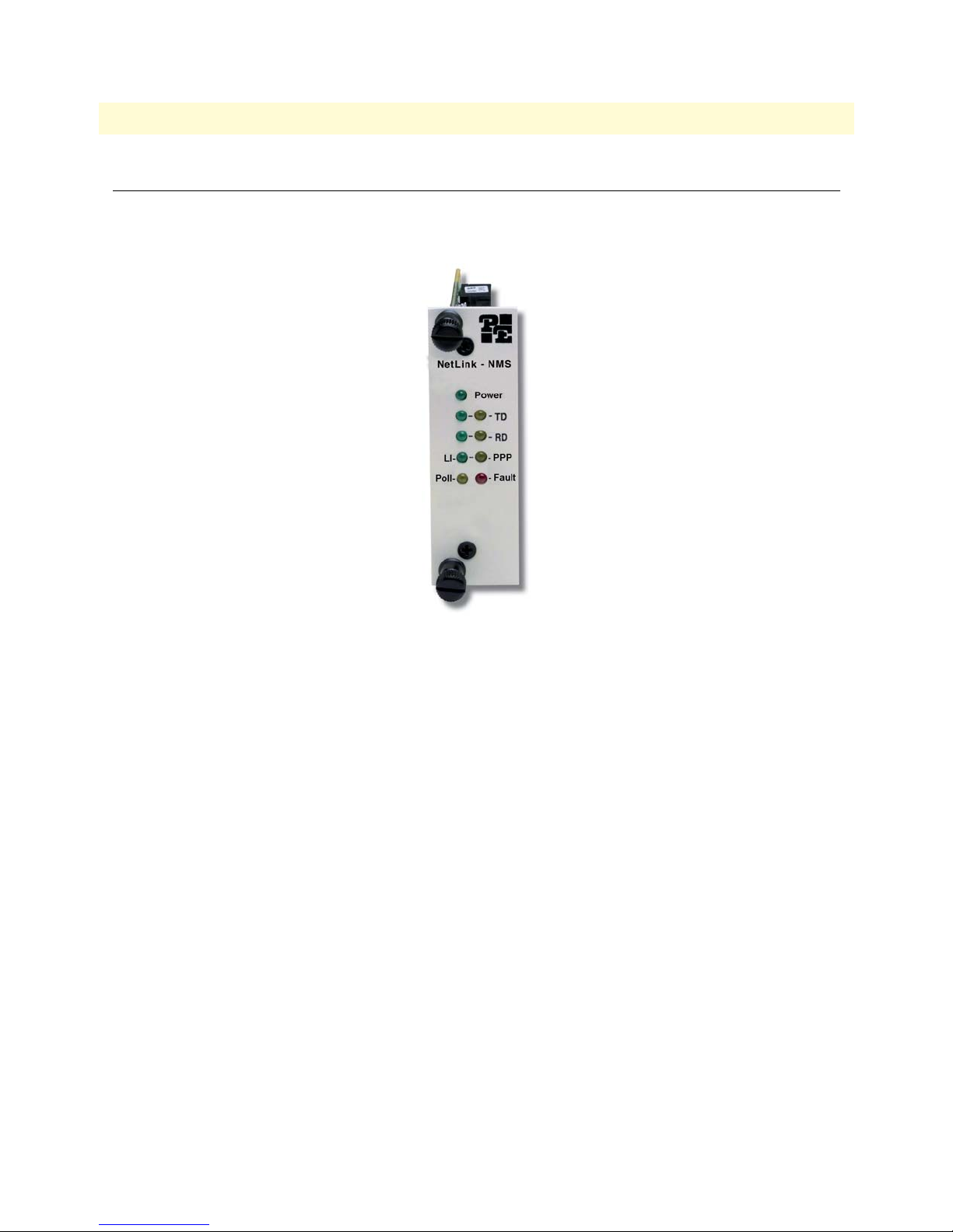
The Model 1001MC NetLink™ SNMP Management Card (see figure 1) enables an SNMP workstation to
configure and monitor multiple Patton NetLink cards racks and their connected standalone units.
Figure 1. Model 1001MC NetLink Management Card
The management card has the following features:
• Connects to the SNMP workstation via a 10Base-T Ethernet (RJ-45) connection
• Uses a standard web browser (Internet Explorer or Netscape Navigator, for example) to configure the
HTTP/HTML management screens.
• Supports generic network management software and MIB walking tools
• Functions as an SNMP proxy agent for Patton NetLink rack cards and their remote standalone units
• FLASH upgradeable through FTP connection
• User selectable traps on a per-card basis
• Compatible with the following rack cards:
- Model 1092ARC KiloModem™ 2 or 4-wire Baseband Modem with 2B1Q Encoding
- Model 1094ARC NetLink 1.152-Mbps HDSL Modem
- Model 1095RC NetLink 2-wire, 2-Mbps mDSL Modem
- Model 2701RC G.703/G.704 Network Termination Unit (NTU)
- Model 2707RC G.703 NTU
- Model 2710RC T1/FT1 CSU/DSU
- Model 2715RC G.703/G.704 NTU
Introduction
Page 12

12
Model 1001MC Operations Guide
1 • Introduction
- Model 3088RC G.SHDSL V.35 - M34
- Model 3088RC G.SHDSL X.21 - DB15
- Model 3088RC G.SHDSL E1 - Dual BNC & RJ-45
- Model 3088RC G.SHDSL Ethernet BR - RJ-45
Note
Your specific model of 1001MC may not support all of the models
listed above.
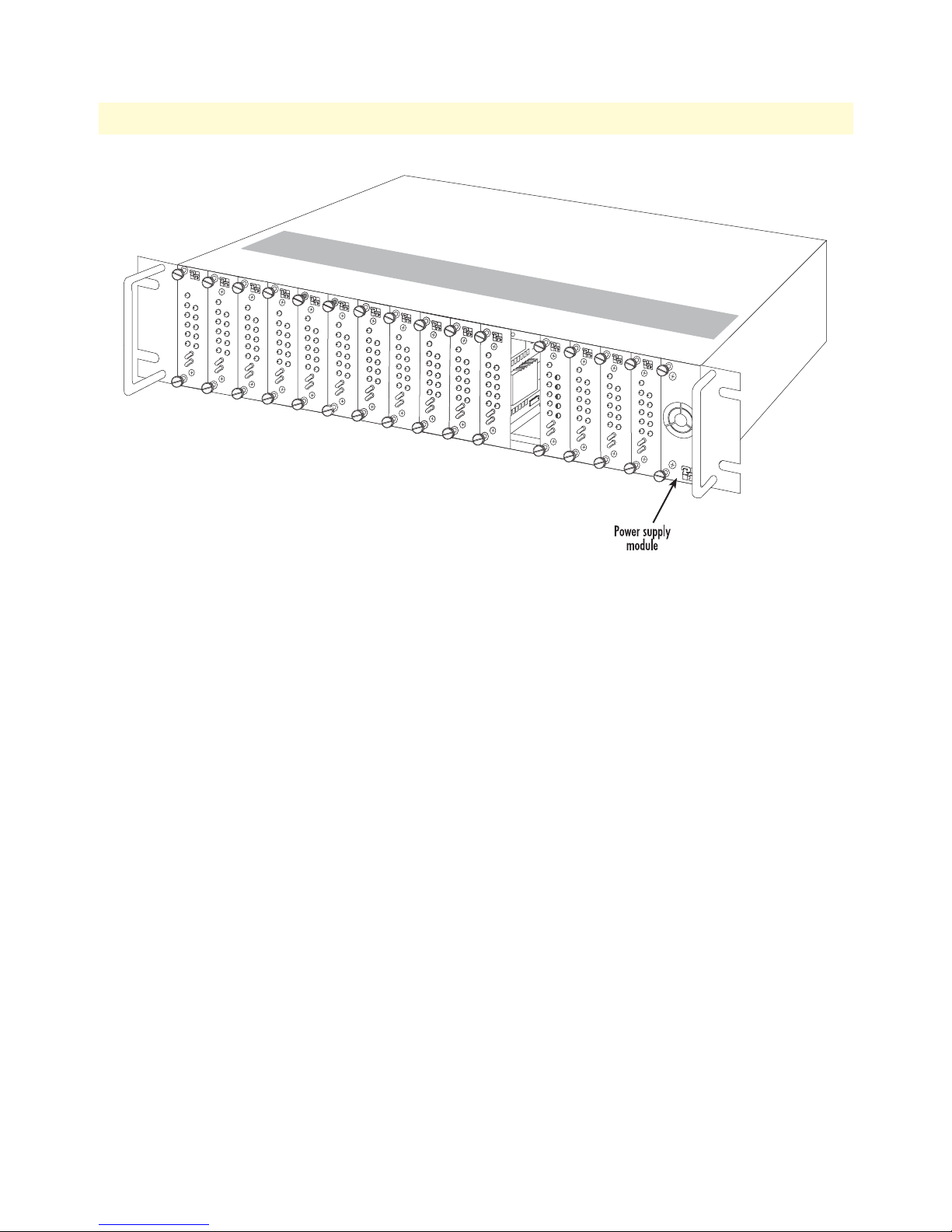
The 1001MC front and rear cards (see figure 2) install into the Model 1001R14/16 NetLink Rack Chassis (see
figure 3). The rack chassis accepts up to 15 cards and a 90–264 VAC or -12/-24/-48 VDC power supply module
(redundant power supply configurations can be created by replacing two rack cards with a second power supply).
Introduction
Figure 2. Model 1001MC front and rear cards
Page 13
13
Model 1001MC Operations Guide
1 • Introduction
Figure 3. Model 1001R14/16 Rack Chassis with power supply
Introduction
Page 14
14
Model 1001MC Operations Guide
1 • Introduction
Model 1001MC management overview
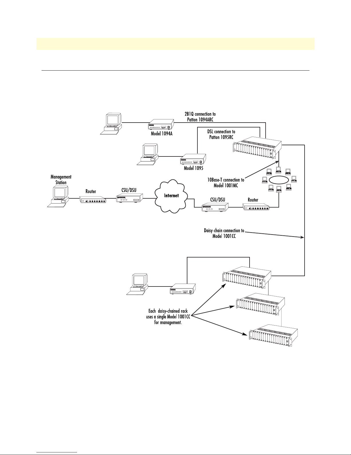
The Model 1001MC uses a 10Base-T Ethernet port to connect to a local LAN (or to any location in the world
via the Internet). Management can be performed using any SNMP station or web browser with the internal
HTTP/HTML management screens. As shown in figure 4, the Model 1001MC can manage multiple racks of
Patton NetLink modems using a daisy-chain configuration and a 1001CC in each additionally managed rack.
Figure 4. Network management through a network using a 10Base-T connection to Model 1001MC
Model 1001MC management overview
Page 15

Chapter 2 Hardware installation
Chapter contents
Introduction..........................................................................................................................................................17
Before you install… ........................................................................................................................................17
Checking the contents… ................................................................................................................................17
Installing the Model 1001MC into the rack chassis ...............................................................................................18
Installing NetLink modem cards ...........................................................................................................................19
Hardware setup for a Model 1092ARC ...........................................................................................................19
Configuring frame ground ........................................................................................................................19
Setting the 1092ARC system address ........................................................................................................20
Polling overview .................................................................................................................................. 20
Polling rack #1 and daisy-chained racks............................................................................................... 20
Hardware setup for a Model 1094ARC ...........................................................................................................22
Configuring frame ground ........................................................................................................................22
Setting the 1094ARC system address ........................................................................................................22
Polling overview .................................................................................................................................. 22
Polling rack #1 and daisy-chained racks............................................................................................... 22
Hardware setup for a Model 1095RC .............................................................................................................24
Configuring frame ground ........................................................................................................................24
Setting the 1095RC system address ...........................................................................................................24
Polling overview .................................................................................................................................. 24
Polling rack #1 and daisy-chained racks............................................................................................... 24
Hardware setup for a Model 2701RC .............................................................................................................26
Configuring frame ground ........................................................................................................................26
Setting the 2701RC system address ...........................................................................................................27
Polling overview .................................................................................................................................. 27
Polling rack #1 and daisy-chained racks............................................................................................... 27
Hardware setup for a Model 2707RC .............................................................................................................28
Configuring frame ground ........................................................................................................................28
Hardware setup for a Model 2710RC .............................................................................................................29
Configuring frame ground ........................................................................................................................29
Hardware setup for a Model 2715RC .............................................................................................................29
Configuring frame ground ........................................................................................................................29
Hardware setup for a Model 3088RC .............................................................................................................29
Configuring frame ground ........................................................................................................................29
Setting the 3088RC system address ...........................................................................................................29
Polling overview .................................................................................................................................. 30
Polling rack #1 and daisy-chained racks............................................................................................... 30
Installing the power supplies..................................................................................................................................31
Verifying 1001MC functioning.............................................................................................................................31
Connecting the cables............................................................................................................................................32
15
Page 16

Model 1001MC Operations Guide 2 • Hardware installation
Installing the Ethernet cable ............................................................................................................................32
Connecting a 10Base-T hub to the 1001MC ............................................................................................33
Connecting a 10Base-T workstation to the 1001MC ................................................................................33
Installing the RS-232 configuration/daisy-chain port cable .............................................................................34
LED indicators ......................................................................................................................................................34
Ethernet LED indicators .................................................................................................................................35
Power LED indicator ......................................................................................................................................35
Heartbeat LED indicator ................................................................................................................................35
Fault LED indicator ........................................................................................................................................35
PPP LED indicator .........................................................................................................................................35
Where to go next...................................................................................................................................................35
16
Page 17

Model 1001MC Operations Guide 2 • Hardware installation
Introduction
Model 1001MC installation consists of the following:
• Installing the front and rear cards into the rack chassis (see section “Installing the Model 1001MC into the
rack chassis” on page 18)
• Configuring and installing the NetLink modem cards (see section “Installing NetLink modem cards” on
page 19)
• Installing the NetLink power supply (or supplies) (see section “Installing the power supplies” on page 31)
• Verifying that the 1001MC functions normally when power is applied (see section “Verifying 1001MC
functioning” on page 31)
• Installing the interface cables (see section “Connecting the cables” on page 32)
When you finish installing the 1001MC, go to chapter 3, “Getting started” on page 36.
Before you install…
Before installing and configuring your Model 1001MC, make sure you have the following items at hand:
• A VT100 terminal or a VT100 terminal emulator for connection to the RS-232 configuration port
• A null modem or a null modem cable to connect your VT100 terminal to the Model 1001MC
• An Ethernet connection to your local LAN
• A locally connected workstation (e.g. PC) that you can use to ping the 1001MC
• An IP address for the Model 1001MC
• The network address space and netmask
• The IP address for the default gateway of your LAN
Checking the contents…
Verify that the shipping container holds the following items:
• 1001MC front and rear cards
• 1001MC CD-ROM that includes this manual
Introduction 17
Page 18

Model 1001MC Operations Guide 2 • Hardware installation
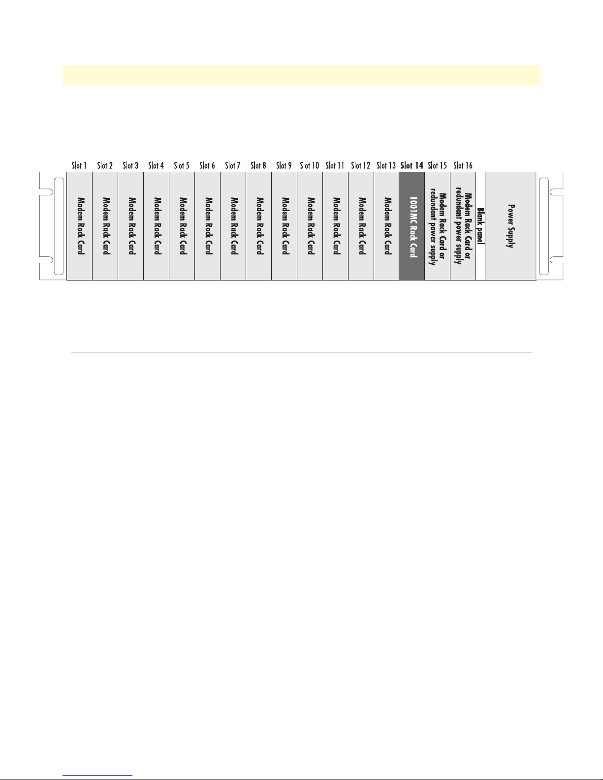
Figure 5. Rack chassis slot layout (rear view)
Installing the Model 1001MC into the rack chassis
The Model 1001MC consists of a front rack card and a rear input/output (I/O) card (see figure 2 on page 12).
The two cards meet inside the rack chassis and plug into each other by way of mating 50-pin card edge connectors. Do the following to install the Model 1001MC cards into the rack chassis:
There are no user-serviceable parts in the power supply section. Voltage setting changes and fuse replacement should only be performed by qualified service personnel. Contact Patton Electronics Technical support at
(301) 975-1007 for more information.
Note The Model 1001MC is hot-swappable, which means that you can
install it into the rack chassis without having to turn off power to the
rack chassis. For the purpose of this procedure, though it is assumed
that power to the rack is OFF at the beginning.
1. Slide the rear I/O card into rear chassis slot 14 (see figure 5) along the metal guide rails.
Note The Model 1001MC installs into rack chassis slot 14 because that
slot provides information about the power supplies to the 1001MC.
If the card is not installed in slot 14, the 1001MC will report power
supply failure.
2. Secure the rear card using the captive fasteners.
Installing the Model 1001MC into the rack chassis 18
Page 19
Model 1001MC Operations Guide 2 • Hardware installation
3. Slide the front rack card into the front chassis slot 14 (see figure 6) until it meets the rear card receptacle.
When that happens, push the front card gently but firmly into the card-edge receptacle of the rear card, it
should click into place.
Figure 6. Rack chassis slot layout (front view)
4. Secure the front rack card using the captive fasteners.
Installing NetLink modem cards
This section contains hardware installation information that affects the following NetLink modems:
• Model 1092ARC (see section “Hardware setup for a Model 1092ARC”)
• Model 1094ARC (see section “Hardware setup for a Model 1094ARC” on page 22)
• Model 1095RC (see section “Hardware setup for a Model 1095RC” on page 24)
• Model 2701RC (see section “Hardware setup for a Model 2701RC” on page 26)
• Model 2707RC (see section “Hardware setup for a Model 2707RC” on page 28)
• Model 2710RC (see section “Hardware setup for a Model 2710RC” on page 29)
• Model 2715RC (see section “Hardware setup for a Model 2715RC” on page 29)
• Model 2088RC (see section “Hardware setup for a Model 3088RC” on page 29)
Hardware setup for a Model 1092ARC
The following must be done to configure your Model 1092ARC hardware for use with the Model 1001MC
network management station:
• Connect frame ground to signal ground (see section “Configuring frame ground”)
• Set the system address (see section “Setting the 1092ARC system address” on page 20)
When you are finished, install the Model 1092ARC front card and rear I/O card using the installation procedures in the manual that came with the modem.
Configuring frame ground
The Model 1001MC uses an internal bus to communicate with the NetLink modems installed in your system.
The Model 1092ARC rear I/O card must have frame ground (GND) connected to signal GND through a
Installing NetLink modem cards 19
Page 20

Model 1001MC Operations Guide 2 • Hardware installation
100-ohm resistor. This is done by configuring a jumper on the modem’s rear I/O card. Refer to the installation
manual that came with the rack card for more information on this jumper setting.
Setting the 1092ARC system address
The manual that was shipped with the 1092ARC defines switch S2 as Address. This switch sets the address of
the modem in the NetLink system. Each card in the chassis is given a unique address through the setting of
switch S2.
Note Standalone units use the address of the rack card that they are con-
nected to.
Polling overview. The Model 1001MC sends poll messages along the internal bus looking for cards installed in
the system. Once a card is found it is placed online and communication with the management station can begin.
If the address of the NetLink modem is not configured or does not match the address range of the rack that it
is installed in, the Model 1001MC may not recognize the card. The address range that is polled is determined
by the configuration of the system. The system administrator must make sure that the software configuration
within the Model 1001MC matches the hardware configuration of the system.
Polling rack #1 and daisy-chained racks. The Model 1001MC uses the number of power supplies in the system to determine what the address range of the individual racks will be. The number of power supplies
installed in each rack is entered on the Modem Information page. If the system is set for two power supplies
installed, the 1001MC will automatically set the number of slots available (displayed on the Modem Information page) in the chassis to 13. If the system is set for a single power supply installed, the 1001MC will automatically set the number of slots available in the chassis to 15.
Using this information, the Model 1001MC will poll the specified address range in each rack. Thus, in a single
power supply system, the address range for rack #1 (the rack with the 1001MC installed) will be from address
1 to address 15
Note The 1001MC is always address 0.
The 1001MC will then begin polling rack #2 on the daisy chain port starting from address 16. In a redundant
power supply system, the address range for rack #1 (the rack with the 1001MC installed) will be from
address 1 to address 13. The 1001MC will then begin polling rack #2 on the daisy chain port starting from
address 14.
The daisy chained racks are set up in the same manner with 13 addresses being available in a redundant system
and 15 addresses being available in single supply system. When you disable a rack the addresses are still set
aside for that rack space. If a power supply is removed, the addressing will not change unless you make the
change through the 1001MC web pages. This allows easy service of the power supplies.
If the address is 0 (all ON position), then the unit will run completely from its DIP-switch configuration. This
can be useful for testing circuits independently of the management system. If an address is placed on the
switch, the unit will boot from its stored flash configuration and begin looking for poll commands from the
Model 1001MC.
Switch S2 allows an 8 bit address to be assigned to a link. The following rules apply to setting the address. Bit
S2-8 is the least significant bit. A bit set to ON is considered a 0. A bit set to OFF is considered a 1. Patton
Electronics suggests that you set your addresses starting with address 1 at the far left of your rack (farthest away
Installing NetLink modem cards 20
Page 21
Model 1001MC Operations Guide 2 • Hardware installation
from the power supplies) and increment the numbers by one as you go from left to right. Setting the addresses
in this manner will make configuration easier as you start using the web page management. An example of this
is shown below.
1 - 2 - 3 - 4 - 5 - 6 - 7 - 8 - 9 - 10 - 11 - 12 - 13 - NMS - PS2 - PS1
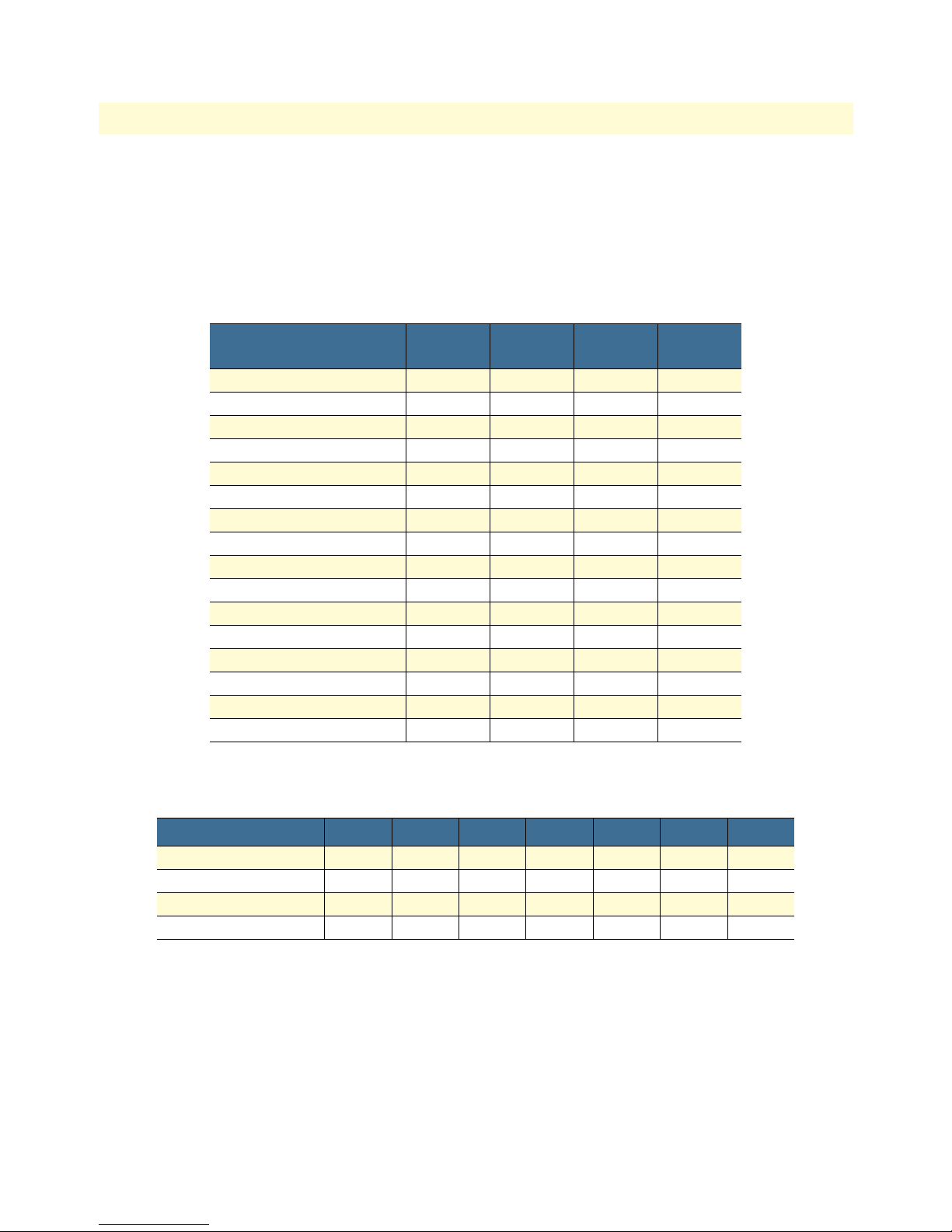
Table 3 shows the bit setting to configure the address. Table 4 shows examples of address settings.
Table 3. Bit setting to configure the address
Upper (Lower) Nibble
0 ON ON ON ON
1 ON ON ON OFF
2 ON ON OFF ON
3 ON ON OFF OFF
4 ON OFF ON ON
5 ON OFF ON OFF
6 ON OFF OFF ON
7 ON OFF OFF ON
8 OFF ON ON ON
9 OFF ON ON OFF
A OFF ON OFF ON
B OFF ON OFF OFF
C OFF OFF ON ON
D OFF OFF ON OFF
E OFF OFF OFF ON
F OFF OFF OFF OFF
(S2-4)
S2-7
(S2-3)
S2-6
(S2-2)
S2-5
(S2-1)
Address in Hex (Dec.) S2-7 S2-6 S2-5 S2-4 S2-3 S2-2 S2-1
0x01 (1) ON ON ON ON ON ON OFF
0x02 (2) ON ON ON ON ON OFF ON
0x10 (16) ON ON OFF ON ON ON ON
0x35 (53) ON OFF OFF ON OFF ON OFF
Installing NetLink modem cards 21
Table 4. Examples of address settings
Page 22

Model 1001MC Operations Guide 2 • Hardware installation
Hardware setup for a Model 1094ARC
The following must be done to configure your Model 1094ARC hardware for use with the Model 1001MC
network management station:
• Connect frame ground to signal ground (see section “Configuring frame ground”)
• Set the system address (see section “Setting the 1094ARC system address”)
When you are finished, install the Model 1094ARC front card and rear I/O card using the installation procedures in the manual that came with the modem.
Configuring frame ground
The Model 1001MC uses an internal bus to communicate with the NetLink modems installed in your system.
The Model 1094ARC rear I/O card must have frame ground (GND) connected to signal GND through a
100-ohm resistor. This is done by configuring a jumper on the modem’s rear I/O card. Refer to the installation
manual that came with the rack card for more information on this jumper setting.
Setting the 1094ARC system address
The manual that was shipped with the 1094RC defines switch S1 as Address. This switch sets the address of
the modem in the NetLink system. Each card in the chassis is given a unique address through the setting of
switch S1.
Note Standalone units use the address of the rack card that they are con-
nected to.
Polling overview. The Model 1001MC sends poll messages along the internal bus looking for cards installed
in the system. Once a card is found it is placed online and communication with the management station
can begin.
If the address of the NetLink modem is not configured or does not match the address range of the rack that it
is installed in, the Model 1001MC may not recognize the card. The address range that is polled is determined
by the configuration of the system. The system administrator must make sure that the software configuration
within the Model 1001MC matches the hardware configuration of the system.
Polling rack #1 and daisy-chained racks. The Model 1001MC uses the number of power supplies in the system to determine what the address range of the individual racks will be. The number of power supplies
installed in each rack is entered on the Modem Information page. If the system is set for two power supplies
installed, the 1001MC will automatically set the number of slots available (displayed on the Modem Information page) in the chassis to 13. If the system is set for a single power supply installed, the 1001MC will automatically set the number of slots available in the chassis to 15.
Using this information, the Model 1001MC will poll the specified address range in each rack. Thus, in a single
power supply system, the address range for rack #1 (the rack with the 1001MC installed) will be from address
1 to address 15
Note The 1001MC is always address 0.
The 1001MC will then begin polling rack #2 on the daisy chain port starting from address 16. In a redundant
power supply system, the address range for rack #1 (the rack with the 1001MC installed) will be from
Installing NetLink modem cards 22
Page 23

Model 1001MC Operations Guide 2 • Hardware installation
address 1 to address 13. The 1001MC will then begin polling rack #2 on the daisy chain port starting from
address 14.
The daisy chained racks are set up in the same manner with 13 addresses being available in a redundant system
and 15 addresses being available in single supply system. When you disable a rack the addresses are still set
aside for that rack space. If a power supply is removed, the addressing will not change unless you make the
change through the 1001MC web pages. This allows easy service of the power supplies.
If the address is 0 (all ON position), then the unit will run completely from its DIP-switch configuration. This
can be useful for testing circuits independently of the management system. If an address is placed on the
switch, the unit will boot from its stored flash configuration and begin looking for poll commands from the
Model 1001MC.
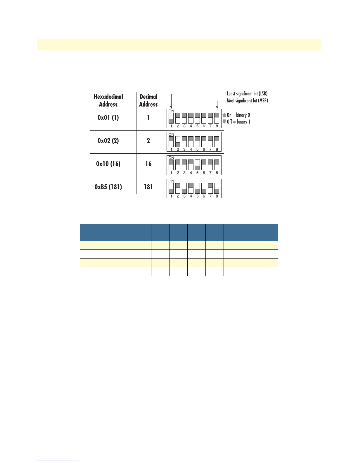
Switch S1 allows an 8 bit address to be assigned to a link. The following rules apply to setting the address. Bit
S1-8 is the least significant bit. A bit set to ON is considered a 0. A bit set to OFF is considered a 1. Patton
Electronics suggests that you set your addresses starting with address 1 at the far left of your rack (farthest away
from the power supplies) and increment the numbers by one as you go from left to right. Setting the addresses
in this manner will make configuration easier as you start using the web page management. An example of this
is shown below.
1 - 2 - 3 - 4 - 5 - 6 - 7 - 8 - 9 - 10 - 11 - 12 - 13 - NMS - PS2 - PS1
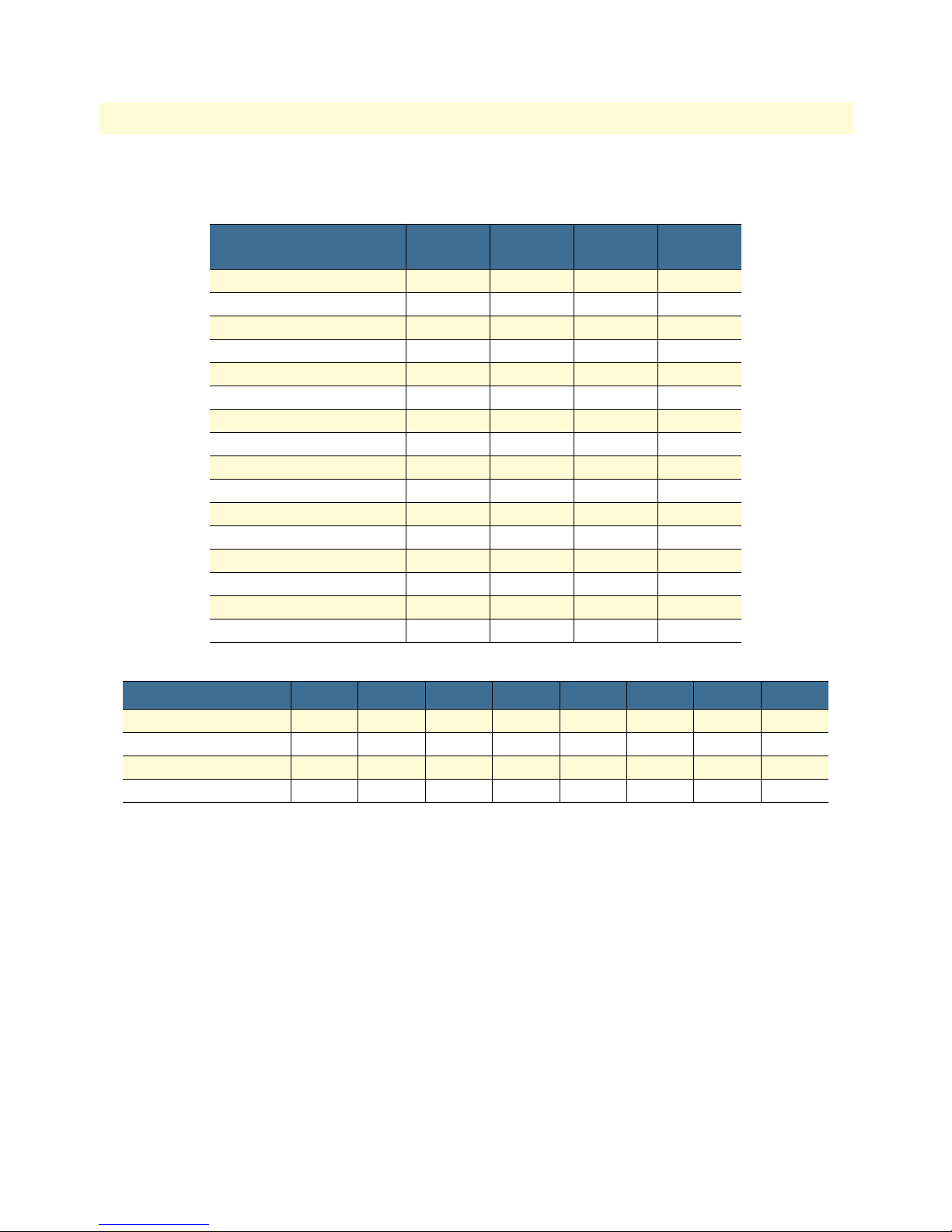
Table 5 shows the bit setting to configure the address. Table 6 shows examples of address settings.
Table 5. Bit setting to configure the address
Upper (Lower) Nibble
0 ON ON ON ON
1 ON ON ON OFF
2 ON ON OFF ON
3 ON ON OFF OFF
4 ON OFF ON ON
5 ON OFF ON OFF
6 ON OFF OFF ON
7 ON OFF OFF ON
8 OFF ON ON ON
9 OFF ON ON OFF
A OFF ON OFF ON
B OFF ON OFF OFF
C OFF OFF ON ON
D OFF OFF ON OFF
E OFF OFF OFF ON
F OFF OFF OFF OFF
S1-1
(S1-5)
S1-2
(S1-6)
S1-3
(S1-7)
S1-4
(S1-8)
Installing NetLink modem cards 23
Page 24

Model 1001MC Operations Guide 2 • Hardware installation
Table 6. Examples of address settings
Address in Hex (Dec.) S1-1 S1-2 S1-3 S1-4 S1-5 S1-6 S1-7 S1-8
0x01 (1) ON ON ON ON ON ON ON OFF
0x02 (2) ON ON ON ON ON ON OFF ON
0x10(16) ON ON ON OFF ON ON ON ON
0xB5(181) OFF ON OFF OFF ON OFF ON OFF
Hardware setup for a Model 1095RC
The following must be done to configure your Model 1095RC hardware for use with the Model 1001MC network management station:
• Connect frame ground to signal ground (see section “Configuring frame ground”)
• Set the system address (see section “Setting the 1094ARC system address”)
When you are finished, install the Model 1095RC front card and rear I/O card using the installation procedures in the manual that came with the modem.
Configuring frame ground
The Model 1001MC uses an internal bus to communicate with the NetLink modems installed in your system.
The Model 1095RC rear I/O card must have frame ground (GND) connected to signal GND through a 100ohm resistor. This is done by configuring a jumper on the modem’s rear I/O card. Refer to the installation
manual that came with the rack card for more information on this jumper setting.
Setting the 1095RC system address
The manual that was shipped with the 1095RC defines switch S1 as Address. This switch sets the address of
the modem in the NetLink system. Each card in the chassis is given a unique address through the setting of
switch S1.
Note Standalone units use the address of the rack card that they are con-
nected to.
Polling overview. The Model 1001MC sends poll messages along the internal bus looking for cards installed
in the system. Once a card is found it is placed online and communication with the management station can
begin.
If the address of the NetLink modem is not configured or does not match the address range of the rack that it
is installed in, the Model 1001MC may not recognize the card. The address range that is polled is determined
by the configuration of the system. The system administrator must make sure that the software configuration
within the Model 1001MC matches the hardware configuration of the system.
Polling rack #1 and daisy-chained racks. The Model 1001MC uses the number of power supplies in the system to determine what the address range of the individual racks will be. The number of power supplies
installed in each rack is entered on the Modem Information page. If the system is set for two power supplies
installed, the 1001MC will automatically set the number of slots available (displayed on the Modem Information page) in the chassis to 13. If the system is set for a single power supply installed, the 1001MC will automatically set the number of slots available in the chassis to 15.
Installing NetLink modem cards 24
Page 25

Model 1001MC Operations Guide 2 • Hardware installation
Using this information, the Model 1001MC will poll the specified address range in each rack. Thus, in a single
power supply system, the address range for rack #1 (the rack with the 1001MC installed) will be from address
1 to address 15
Note The 1001MC is always address 0.
The 1001MC will then begin polling rack #2 on the daisy chain port starting from address 16. In a redundant
power supply system, the address range for rack #1 (the rack with the 1001MC installed) will be from
address 1 to address 13. The 1001MC will then begin polling rack #2 on the daisy chain port starting from
address 14.
The daisy chained racks are set up in the same manner with 13 addresses being available in a redundant system
and 15 addresses being available in single supply system. When you disable a rack the addresses are still set
aside for that rack space. If a power supply is removed, the addressing will not change unless you make the
change through the 1001MC web pages. This allows easy service of the power supplies.
If the address is 0 (all ON position), then the unit will run completely from its DIP-switch configuration. This
can be useful for testing circuits independently of the management system. If an address is placed on the
switch, the unit will boot from its stored flash configuration and begin looking for poll commands from the
Model 1001MC.
Switch S1 allows an 8 bit address to be assigned to a link. The following rules apply to setting the address. Bit
S1-8 is the least significant bit. A bit set to ON is considered a 0. A bit set to OFF is considered a 1. Patton
Electronics suggests that you set your addresses starting with address 1 at the far left of your rack (farthest away
from the power supplies) and increment the numbers by one as you go from left to right. Setting the addresses
in this manner will make configuration easier as you start using the web page management. An example of this
is shown below.
1 - 2 - 3 - 4 - 5 - 6 - 7 - 8 - 9 - 10 - 11 - 12 - 13 - NMS - PS2 - PS1
Installing NetLink modem cards 25
Page 26
Model 1001MC Operations Guide 2 • Hardware installation
Table 7 shows the bit setting to configure the address. Table 8 shows examples of address settings.
Table 7. Bit setting to configure the address
Upper (Lower) Nibble
0 ON ON ON ON
1 ON ON ON OFF
2 ON ON OFF ON
3 ON ON OFF OFF
4 ON OFF ON ON
5 ON OFF ON OFF
6 ON OFF OFF ON
7 ON OFF OFF ON
8 OFF ON ON ON
9 OFF ON ON OFF
A OFF ON OFF ON
B OFF ON OFF OFF
C OFF OFF ON ON
D OFF OFF ON OFF
E OFF OFF OFF ON
F OFF OFF OFF OFF
Table 8. Examples of address settings
S1-1
(S1-5)
S1-2
(S1-6)
S1-3
(S1-7)
S1-4
(S1-8)
Address in Hex (Dec.) S1-1 S1-2 S1-3 S1-4 S1-5 S1-6 S1-7 S1-8
0x01 (1) ON ON ON ON ON ON ON OFF
0x02 (2) ON ON ON ON ON ON OFF ON
0x10(16) ON ON ON OFF ON ON ON ON
0xB5(181) OFF ON OFF OFF ON OFF ON OFF
Hardware setup for a Model 2701RC
The following must be done to configure your Model 2701RC hardware for use with the Model 1001MC network management station:
• Connect frame ground to signal ground (see section “Configuring frame ground”)
• Set the system address (see section “Setting the 2701RC system address”)
When you are finished, install the Model 2701RC front card and rear I/O card using the installation procedures in the manual that came with the modem.
Configuring frame ground
The Model 1001MC uses an internal bus to communicate with the NetLink modems installed in your system.
The Model 2701RC rear I/O card must have frame ground (GND) connected to signal GND through a 100ohm resistor. This is done by configuring a jumper on the modem’s rear I/O card. Refer to the installation
manual that came with the rack card for more information on this jumper setting.
Installing NetLink modem cards 26
Page 27

Model 1001MC Operations Guide 2 • Hardware installation
Setting the 2701RC system address
The manual that was shipped with your NetLink-E1 unit specifies switch S3 for the card address in the
NetLink System. Each card in the chassis is given a unique address through the setting of switch S3.
Note Standalone units use the address of the rack card that they are con-
nected to.
Polling overview. The Model 1001MC sends “poll” messages along the internal bus looking for cards installed
in the system. Once a card is found it is placed “online” and communication with the management station
can begin.
If the address of the NetLink modem is not configured or does not match the address range of the rack that it
is installed in, the Model 1001MC may not recognize the card. The address range that is polled is determined
by the configuration of the system. The system administrator must make sure that the software configuration
within the Model 1001MC matches the hardware configuration of the system.
Polling rack #1 and daisy-chained racks. The Model 1001MC uses the number of power supplies in the system to determine what the address range of the individual racks will be. The number of power supplies
installed in each rack is entered on the Modem Information page. If the system is set for two power supplies
installed, the 1001MC will automatically set the number of slots available (displayed on the Modem Information page) in the chassis to 13. If the system is set for a single power supply installed, the 1001MC will automatically set the number of slots available in the chassis to 15.
Using this information, the Model 1001MC will poll the specified address range in each rack. Thus, in a single
power supply system, the address range for rack #1 (the rack with the 1001MC installed) will be from address
1 to address 15
Note The 1001MC is always address 0.
The 1001MC will then begin polling rack #2 on the daisy chain port starting from address 16. In a redundant
power supply system, the address range for rack #1 (the rack with the 1001MC installed) will be from
address 1 to address 13. The 1001MC will then begin polling rack #2 on the daisy chain port starting from
address 14.
The daisy chained racks are set up in the same manner with 13 addresses being available in a redundant system
and 15 addresses being available in single supply system. When you disable a rack the addresses are still set
aside for that rack space. If a power supply is removed, the addressing will not change unless you make the
change through the 1001MC web pages. This allows easy service of the power supplies.
The 2701RCs are shipped to use DIP switch configuration as default. Software configuration can be enabled
through either the VT-100 screens or through the 1001MC NMS. To use the NMS, switch S2-7 must be set
to the “OFF” position, otherwise the VT-100 port is active.
Switch S3 allows a decimal address to be assigned to a link. The following rules apply to setting the address:
• S3-1 is the LSB and S3-8 is the MSB
• Patton Electronics suggests that you set your addresses starting with address 1 at the far left of your rack
(farthest away from the power supplies) and increment the numbers by one as you go from left to right. Setting the addresses in this manner will make configuration easier as you start using the web page management. An example of this is below.
Installing NetLink modem cards 27
Page 28
Model 1001MC Operations Guide 2 • Hardware installation
1 - 2 - 3 - 4 - 5 - 6 - 7 - 8 - 9 - 10 - 11 - 12 - 13 - NMS - PS2 - PS1
Figure 7 shows the bit setting to configure the address. Table 9 shows examples of address settings.
Figure 7. Bit setting to configure the address
Table 9. Examples of address settings
Hex Address
(Decimal Address)
0x01 (1) ON ON ON ON ON ON ON OFF
0x02 (2) ON ON ON ON ON ON OFF ON
0x10(16) ON ON ON OFF ON ON ON ON
0xB5(181) OFF ON OFF OFF ON OFF ON OFF
S3-8 S3-7 S3-6 S3-5 S3-4 S3-3 S3-2 S3-1
Hardware setup for a Model 2707RC
The following must be done to configure your Model 2707RC hardware for use with the Model 1001MC network management station:
• Connect frame ground to signal ground (see section “Configuring frame ground”)
When you are finished, install the Model 2707RC front card and rear I/O card using the installation procedures in the manual that came with the modem.
Configuring frame ground
The Model 1001MC uses an internal bus to communicate with the NetLink modems installed in your system.
The Model 2707RC rear I/O card must have frame ground (GND) connected to signal GND through a 100ohm resistor. This is done by configuring a jumper on the modem’s rear I/O card. Refer to the installation
manual that came with the rack card for more information on this jumper setting.
Installing NetLink modem cards 28
Page 29

Model 1001MC Operations Guide 2 • Hardware installation
Hardware setup for a Model 2710RC
The following must be done to configure your Model 2710RC hardware for use with the Model 1001MC network management station:
• Connect frame ground to signal ground (see section “Configuring frame ground”)
When you are finished, install the Model 2710RC front card and rear I/O card using the installation procedures in the manual that came with the modem.
Configuring frame ground
The Model 1001MC uses an internal bus to communicate with the NetLink modems installed in your system.
The Model 2710RC rear I/O card must have frame ground (GND) connected to signal GND through a 100ohm resistor. This is done by configuring a jumper on the modem’s rear I/O card. Refer to the installation
manual that came with the rack card for more information on this jumper setting.
Hardware setup for a Model 2715RC
The following must be done to configure your Model 2715RC hardware for use with the Model 1001MC network management station:
• Connect frame ground to signal ground (see section “Configuring frame ground”)
When you are finished, install the Model 2715RC front card and rear I/O card using the installation procedures in the manual that came with the modem.
Configuring frame ground
The Model 1001MC uses an internal bus to communicate with the NetLink modems installed in your system.
The Model 2715RC rear I/O card must have frame ground (GND) connected to signal GND through a 100ohm resistor. This is done by configuring a jumper on the modem’s rear I/O card. Refer to the installation
manual that came with the rack card for more information on this jumper setting.
Hardware setup for a Model 3088RC
The following must be done to configure your Model 3088RC hardware for use with the Model 1001MC network management station:
• Connect frame ground to signal ground (see section “Configuring frame ground”)
• Set the system address (see section “Setting the 2701RC system address”)
When you are finished, install the Model 3088RC front card and rear I/O card using the installation procedures in the manual that came with the modem.
Configuring frame ground
The Model 1001MC uses an internal bus to communicate with the NetLink modems installed in your system.
The Model 3088RC rear I/O card must have frame ground (GND) connected to signal GND through a 100ohm resistor. This is done by configuring a jumper on the modem’s rear I/O card. Refer to the installation
manual that came with the rack card for more information on this jumper setting.
Setting the 3088RC system address
The manual that was shipped with your NetLink-E1 unit specifies switch S3 for the card address in the
NetLink System. Each card in the chassis is given a unique address through the setting of switch S3.
Installing NetLink modem cards 29
Page 30

Model 1001MC Operations Guide 2 • Hardware installation
Note Standalone units use the address of the rack card that they are con-
nected to.
Polling overview. The Model 1001MC sends “poll” messages along the internal bus looking for cards installed
in the system. Once a card is found it is placed “online” and communication with the management station
can begin.
If the address of the NetLink modem is not configured or does not match the address range of the rack that it
is installed in, the Model 1001MC may not recognize the card. The address range that is polled is determined
by the configuration of the system. The system administrator must make sure that the software configuration
within the Model 1001MC matches the hardware configuration of the system.
Polling rack #1 and daisy-chained racks. The Model 1001MC uses the number of power supplies in the system to determine what the address range of the individual racks will be. The number of power supplies
installed in each rack is entered on the Modem Information page. If the system is set for two power supplies
installed, the 1001MC will automatically set the number of slots available (displayed on the Modem Information page) in the chassis to 13. If the system is set for a single power supply installed, the 1001MC will automatically set the number of slots available in the chassis to 15.
Using this information, the Model 1001MC will poll the specified address range in each rack. Thus, in a single
power supply system, the address range for rack #1 (the rack with the 1001MC installed) will be from address
1 to address 15
Note The 1001MC is always address 0.
The 1001MC will then begin polling rack #2 on the daisy chain port starting from address 16. In a redundant
power supply system, the address range for rack #1 (the rack with the 1001MC installed) will be from
address 1 to address 13. The 1001MC will then begin polling rack #2 on the daisy chain port starting from
address 14.
The daisy chained racks are set up in the same manner with 13 addresses being available in a redundant system
and 15 addresses being available in single supply system. When you disable a rack the addresses are still set
aside for that rack space. If a power supply is removed, the addressing will not change unless you make the
change through the 1001MC web pages. This allows easy service of the power supplies.
Switch S3 allows a decimal address to be assigned to a link. The following rules apply to setting the address:
• S3-1 is the LSB and S3-8 is the MSB
• Patton Electronics suggests that you set your addresses starting with address 1 at the far left of your rack
(farthest away from the power supplies) and increment the numbers by one as you go from left to right. Setting the addresses in this manner will make configuration easier as you start using the web page management. An example of this is below.
1 - 2 - 3 - 4 - 5 - 6 - 7 - 8 - 9 - 10 - 11 - 12 - 13 - NMS - PS2 - PS1
Installing NetLink modem cards 30
Page 31

Model 1001MC Operations Guide 2 • Hardware installation
Figure 7 shows the bit setting to configure the address. Table 9 shows examples of address settings.
Figure 8. Bit setting to configure the address
Table 10. Examples of address settings
Hex Address
(Decimal Address)
0x01 (1) ON ON ON ON ON ON ON OFF
0x02 (2) ON ON ON ON ON ON OFF ON
0x10(16) ON ON ON OFF ON ON ON ON
0xB5(181) OFF ON OFF OFF ON OFF ON OFF
S3-8 S3-7 S3-6 S3-5 S3-4 S3-3 S3-2 S3-1
Installing the power supplies
Refer to the installation manual that came with the power supply (or supplies) to install the supply and rear
power entry module into the rack chassis.
Verifying 1001MC functioning
1. Apply power to the rack system, verify that the green Power LED on the Model 1001MC front card illumi-
nates.
2. Turn off power to the rack system, verify that the green Power LED on the Model 1001MC front card
extinguishes.
Installing the power supplies 31
Page 32

Model 1001MC Operations Guide 2 • Hardware installation
Connecting the cables
Installing 1001MC rear I/O card cables takes place in the following order:
Do not work on the system or connect or disconnect cables during periods of
lightning activity.
1. Installing the 10Base-T Ethernet cable onto the 10Base-T port (see figure 9) (see “Installing the Ethernet
cable” on page 32).
2. Installing the cable onto the RS-232 configuration/daisy-chain port (see figure 9) (see “Installing the RS-
232 configuration/daisy-chain port cable” on page 34).
Figure 9. Rear I/O card ports
Installing the Ethernet cable
The RJ-45 Ethernet jack on the rear I/O card of the Model 1001MC is designed to connect directly to a
10Base-T network. Figure 10 shows the RJ-45 jack pin-out diagram. Refer to the following sections when con-
structing Ethernet cables to connect to the Patton Model 1001MC.
Figure 10. 1001MC 10Base-T Ethernet port pin-out diagram
Connecting the cables 32
Page 33

Model 1001MC Operations Guide 2 • Hardware installation
Connecting a 10Base-T hub to the 1001MC
The Ethernet 10Base-T port on the rear of the 1001MC connects directly to a 10Base-T hub or repeater using
RJ-45 unshielded twisted-pair cable that is wired straight-through (see figure 11).
Note Cable lengths should not exceed 330 feet (100 m) when using Type 4
or 5 cable.
Figure 11. Hub wiring diagram
Connecting a 10Base-T workstation to the 1001MC
The 10Base-T port on the 1001MC connected to a workstation by means of a cross-connect cable. Refer to
figure 12 to build a cross-connect cable that connects between the 10Base-T port on a workstation’s NIC and
the 1001MC’s 10Base-T port.
Note Cable lengths should not exceed 330 feet (100 m) when using Type 4
or 5 cable.
Figure 12. Workstation wiring diagram
Connecting the cables 33
Page 34

Model 1001MC Operations Guide 2 • Hardware installation
Installing the RS-232 configuration/daisy-chain port cable
The DB-25 connector is a DTE-configured RS-232 port that is used to set up your IP address, subnet mask,
and default configuration. After the system is set up, the configuration port can be used to connect to a Model
1001CC in a separate rack if you are daisy-chaining multiple racks.
Figure 13. RS-232 DTE configuration port
Note The configuration port on your 1001MC, being a DTE, requires a
null modem or equivalent cable when connecting to a terminal.
Using personal computer communications software (Procomm, Windows Terminal, BitCom, PC Anywhere,
etc.), set the configuration of your communications software to the following parameters:
• Data Rate: 19,200 bps
• Async. Character Format: 8 Data Bits, 1 Stop Bit, No Parity
• Terminal Emulation: VT-100 (or similar) terminal emulation
LED indicators
The 1001MC front card has status LEDs (see figure 14) that display at-a-glance the current operational status
of the 1001MC.
LED indicators 34
Figure 14. Front card LEDs
Page 35

Model 1001MC Operations Guide 2 • Hardware installation
Ethernet LED indicators
The Ethernet LEDs convey transmit and receive data activity as well as the status of the link (see table 11).
Table 11. Ethernet LED indicators
LED Color Function Description
LI Green Twisted pair link indication On = Connected to active LAN
Off = Not connected to active LAN
TD Yellow/Green Transmit data from 1001MC
to LAN
RD Yellow/Green Receive data at 1001MC from LAN Yellow = Idle condition
Yellow = Idle condition
Green = Toggles yellow/green with activity
Green = Toggles yellow/green with activity
Power LED indicator
The power LED shows the power status of the Model 1001MC (see table 12).
Table 12. Power LED indicator
LED Color Function Description
Power Green Power status On = Power is ON
Off = Power is OFF
Heartbeat LED indicator
Table 13. Poll LED indicator
LED Color Function Description
Poll Yellow Heartbeat Toggles when packet TX is on the backplane bus
Fault LED indicator
Table 14. Fault LED indicator
LED Color Function Description
Fault Red Fault condition On = Signals hardware fault
Off = No hardware fault
PPP LED indicator
Note The PPP capability will be included in future releases as a software
upgrade to the 1001MC.
Where to go next
Congratulations, you have finished installing the Model 1001MC! Now go to chapter 3, “Getting started” on
page 36.
Where to go next 35
Page 36

Chapter 3 Getting started
Chapter contents
Introduction..........................................................................................................................................................37
Booting the Model 1001MC.................................................................................................................................37
Installing the Model 1001MC RS-232 daisy-chain port cable ...............................................................................39
Setting the address range for your NetLink modems .......................................................................................40
Introduction to the internal HTTP/HTML management pages ............................................................................41
Logging into the HTTP/HTML administration pages ....................................................................................41
HTTP/HTML and SNMP object format .......................................................................................................42
Saving HTTP/HTML object changes....................................................................................................................42
Help screens ....................................................................................................................................................42
HTTP/HTML web page navigation ...............................................................................................................42
Home ........................................................................................................................................................44
About 1001MC ........................................................................................................................................44
Configure Cards ........................................................................................................................................45
Download .................................................................................................................................................45
System Log ................................................................................................................................................45
SNMP .......................................................................................................................................................45
System Config ...........................................................................................................................................45
Help ..........................................................................................................................................................45
Where to go next…...............................................................................................................................................46
36
Page 37

Model 1001MC Operations Guide 3 • Getting started
Introduction
To complete this section you will need the following:
• a VT-100 terminal or terminal emulator
• a null-modem cable
• an IP address for your box
• a subnet mask for your box
• the IP address of the default gateway for your LAN
Booting the Model 1001MC
Note If you are starting the Model 1001MC for the first time, you must log
in via the rear panel RS-232 configuration port and set the IP
address, subnet mask, and default gateway.
Note The configuration port on your 1001MC is a DTE, which requires a
null modem or equivalent cable when connecting to a terminal.
1. Using personal computer communications software (Procomm, Windows Terminal, BitCom, PC Any-
where, etc.), set the configuration of your communications software to the following parameters:
– Data rate: 19,200 bps
– Async. character format: 8 data bits, 1 stop bit, no parity
– Terminal emulation: VT-100 (or similar) terminal emulation
2. Connect the RS-232/V.24 port of the terminal to the rear panel RS-232 configuration port of the
1001MC through a null-modem. The RS-232 port is configured as data terminal equipment (DTE).
3. Apply power to the rack system. The Model 1001MC will begin a series of diagnostic tests to exercise the
internal sub-systems in the unit. You must halt the power up sequence in order to enter a new IP address,
mask, and default gateway into the box. Press the b key three times when you see the following:
DRAM:Configure Complete
FLASH:Configure Complete
Boot Version May 11 1999 14:44:24
Validating operation code
Valid operational code, Hit ‘b’ three times to stop operational boot
Introduction 37
Page 38

Model 1001MC Operations Guide 3 • Getting started
5. After pressing the b key three times the system will display the following:
Timer Started May 11 1999 14:44:24
Timer installed
Clock installed
Trying the console
---Ethernet Hardware---
Address: 00.a0.ba.00.01.71
---Current IP settings---
IP:192.168.200.1
Mask:255.255.255.0
Gateway:209.49.110.1
Change IP settings (y/n)?
4. Type Y to change the IP address. You will be prompted to enter a new IP address, mask, and default gate-
way as follows:
---Current IP settings---
IP:209.49.110.188
Mask:255.255.255.0
Gateway:209.49.110.1
Change IP settings (y/n)? y
User Set IP:209.49.110.188
User Set Mask:255.255.255.0
User Set Gateway:209.49.110.1
---Settings to save---
IP:209.49.110.188
Mask:255.255.255.0
Gateway:209.49.110.1
Save these settings (y/n)? Y
5. After entering the information, the system will prompt you to save the IP settings. Type Y to save the
new settings.
6. The Model 1001MC will prompt you for changes to the hardware revision that your unit requires
as follows:
---Hardware Initialization---
Current Hardware Revision B
Change Hardware Revision (y/n)? n
Note In most cases you should select N to keep the current revision. The
hardware revision should only be changed if you are upgrading to the
latest firmware release.
Booting the Model 1001MC 38
Page 39

Model 1001MC Operations Guide 3 • Getting started
Note To RESET to factory configuration the user must type e three times
anytime during the boot sequence upon power-up. The console will
display the following messages:
Are you sure you want to erase current configuration (y/n)?y
If y is entered, the current configuration will be erased and the factory
default configuration will be restored.
Are you sure you want to erase current configuration (y/n)?n
If n is entered, the boot sequence will continue without any changes
to configuration.
7. Turn power off and on again reboot the system with the new settings. After your system reboots, log into
the box using a standard web browser from your network.
8. Disconnect the cable from the rear panel RS-232 configuration port of the 1001MC.
9. If you are installing a daisy-chain cable to the RS-232 configuration port of the 1001MC, go to section
“Installing the Model 1001MC RS-232 daisy-chain port cable”. Otherwise, go to section “Setting the
address range for your NetLink modems”.
Installing the Model 1001MC RS-232 daisy-chain port cable
Using the Model 1001MC RS-232 Daisy Chain Port and an EIA-510 cable, your Model 1001MC can manage up to seven additional racks. Each daisy chained rack must have a Model 1001CC Controller Card
installed. The Model 1001MC—in combination with the Model 1001CC—can control up to 120 NetLink
rack card modems and their remote CPE devices. This section describes how to connect your Model 1001MC
to additional racks.
Note If you plan to build your own RS-232-to-EIA-561 converter to con-
nect the Model 1001MC to the Model 1001CC, refer to the Model
1001CC manual for EIA-561 interface pinouts.
Installing the Model 1001MC RS-232 daisy-chain port cable 39
Page 40

Model 1001MC Operations Guide 3 • Getting started
Figure 15. Configuring a daisy-chain network
Setting the address range for your NetLink modems
The Model 1001MC polls the system looking for NetLink modems. If the address of the NetLink modem is
not configured or does not match the rack that it is installed in, the Model 1001MC may not find the card.
The address range that is polled is determined by the configuration of the system. The system administrator
must make sure that the software configuration within the Model 1001MC matches the hardware configuration of the system.
The Model 1001MC uses the number of power supplies in the system to determine what the address range of
the individual racks will be. The number of power supplies installed in each rack is entered on the Modem
Information page. If the system is set for two power supplies installed, the 1001MC will automatically set the
number of slots available (displayed on the Modem Information page) in the chassis to 13. If the system is set
for a single power supply installed, the 1001MC will automatically set the number of slots available in the
chassis to 15.
Using this information, the Model 1001MC will poll the specified address range in each rack. Thus, in a single
power supply system, the address range for rack #1 (the rack with the 1001MC installed) will be from address
1 to address 15
Note The 1001MC is always address 0.
Installing the Model 1001MC RS-232 daisy-chain port cable 40
Page 41

Model 1001MC Operations Guide 3 • Getting started
The 1001MC will then begin polling rack #2 on the daisy chain port starting from address 16. in a redundant
power supply system, the address range for rack #1 (the rack with the 1001MC installed) will be from address
1 to address 13. The 1001MC will then begin polling rack #2 on the daisy chain port starting from address 14.
The daisy-chained racks are setup in the same manner with 13 addresses being available in a redundant system
and 15 addresses being available in single supply system. When you disable a rack the addresses are still set
aside for that rack space. If a power supply is removed, the addressing will not change unless you make the
change through the 1001MC web pages. This allows easy service of the power supplies.
Introduction to the internal HTTP/HTML management pages
This section explains how to configure the internal HTTP/HTML management pages to manage your Patton
NetLink System. The system can also be managed by using an SNMP Network Management Station using a
standard SNMP software package or MIB walking tool.
Logging into the HTTP/HTML administration pages
To log into the HTTP/HTML administration pages, you must enter the 4-octet Internet protocol (IP)
address—in the format http://your.server.ip.address (for example, http://201.168.15.12)—as the universal
resource locator (URL) into a World-Wide Web (WWW) browser. After you enter the IP address, the
1001MC will prompt for your user name and password as shown in figure 16.
Figure 16. 1001MC login window
The Model 1001MC has two levels of password protection:
• superuser—The superuser password level lets you view statistics and make configuration changes to the sys-
tem. To log in as a superuser, type the word superuser, all lower case, as the username and password
• monitor—The monitor level password enables you to view statistics, but it will not let you make any config-
uration changes. To log into the system at the monitor level, type monitor, all lower case, for the username
and password.
Note The superuser and monitor passwords are set in the unit as the
default passwords. For proper security, make sure that during your
initial setup, you change the passwords (see section “System Informa-
tion” on page 246 for information on how to change passwords).
Introduction to the internal HTTP/HTML management pages 41
Page 42
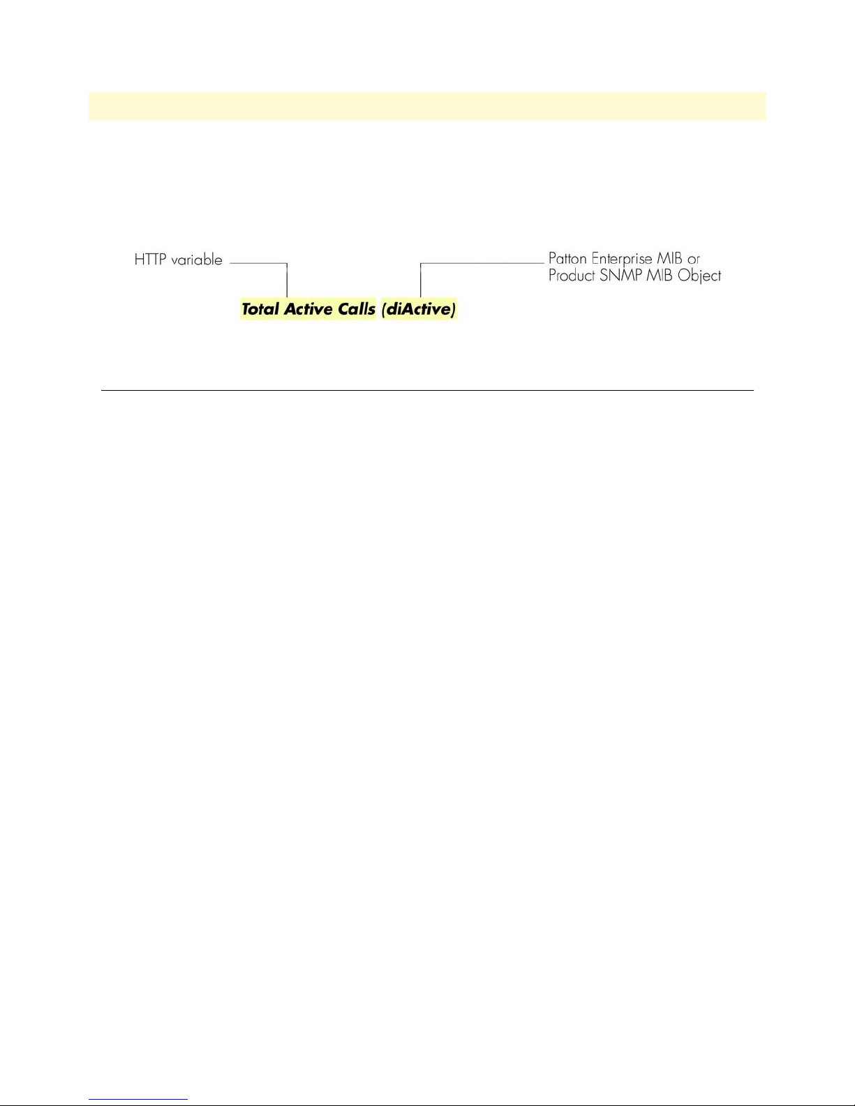
Model 1001MC Operations Guide 3 • Getting started
HTTP/HTML and SNMP object format
In this document, we shall describe the variables found on each of the internal HTTP/HTML pages. This
description will include brief definitions of the Patton Enterprise MIB or SNMP MIB II object identifiers
wherever applicable. The format of the variables will resemble figure 17.
Figure 17. HTTP/HTML and SNMP object format
Saving HTTP/HTML object changes
Sometimes you will need to save changes that you have made in the HTTP/HTML pages. Do the following to
make changes to read/write variables:
1. Select the appropriate Modify screen.
2. Make changes to the desired parameter.
3. Click on the Submit button.
4. Return to the HOME screen.
5. Click on the Record Current Configuration button.
Note Make sure you follow steps 1 through 5 when modifying the
HTTP/HTML pages. Otherwise, your changes will be lost when the
1001MC is power-cycled.
Help screens
The Model 1001MC web pages have built-in help screens that enable you to get information about the variables that are being described. Each web page contains several headings that describe the section that is being
defined. Some of the headings are hyperlinks to the help screen for that page. The new window will automatically scroll to the help area that was requested. You may also scroll through this page to view help information
about other sections of the page. In some cases, the headings for the tables will be shown as hyperlinks, these
hyperlinks, work the same as was previously discussed, showing the help screen for that column of the table.
HTTP/HTML web page navigation
This section describes how to navigate the internal HTTP/HTML web pages on the Model 1001MC. The
diagram below shows how all of the web pages are linked together. Following figure 18, there is a brief descrip-
tion of each page. For more detailed information about each web page, refer to chapter 10, “HTTP/HTML
web page reference” on page 220.
Saving HTTP/HTML object changes 42
Page 43

Model 1001MC Operations Guide 3 • Getting started
Figure 18. 1001MC command map
Saving HTTP/HTML object changes 43
Page 44

Model 1001MC Operations Guide 3 • Getting started
After logging in, the system displays the HOME page (see figure 19).
Figure 19. HOME page
Home
The HOME page displays a quick overview of the system including; error and warning indications, software
information, box names, number of modems installed, and so on.
On the left side of the HOME page is the Navigation View. The list on the left side of the screen allows you to
navigate to any page from this point. The navigation page will always be available to you so you can change
from one page to the next.
The Record Current Configuration button lets you store configuration changes made to the box.
Note If configuration changes are not stored into memory, they will be lost
if the unit is powered down.
The Hard Reset button forces the 1001MC to perform a reset. This will not reset the individual cards in the
rack only the 1001MC. If you would like to perform a hardware reset on the individual cards, refer to the Slot
Configuration page. For more information, refer to section “HOME” on page 228.
About 1001MC
The About 1001MC page gives a more in-depth overview of the system that presented on the HOME page.
This page also provides contact information about Patton Electronics. For more information, refer to section
“About 1001MC” on page 231.
Saving HTTP/HTML object changes 44
Page 45

Model 1001MC Operations Guide 3 • Getting started
Configure Cards
Clicking on the Configure Cards hyperlink displays the System Level Information page. This page is the starting
point for the configuration and management of your Patton NetLink modems. This page enables you to quickly
identify potential problems and view statistics on a per-rack basis. You can also disable racks from this level. For
more information, refer to section “” on page 249.
Download
Note Model 1094RC and 1095RC only.
The Download page enables you to perform software upgrades on the NetLink rack card modems installed in
the system. New software for the modems can be obtained from Patton Electronics and uploaded into the
1001MC system via a file-transfer protocol (FTP) connection. For more information, refer to section “Down-
load” on page 249.
System Log
The System Log page displays Syslog messages. Syslog messaging is a reporting tool used in the Model
1001MC to log run-time operations. There are several levels of messages and you can set the system to report
only messages above a certain level. For more information, refer to section “System Log” on page 251.
SNMP
The SNMP web page enables you to download the Patton Enterprise MIBs for the Model 1001MC. These
MIBs are required if you plan to manage the system using a network management station (NMS) instead of
the web page manager. For more information, refer to section “SNMP” on page 258.
System Config
The System Config web page is where Model 1095RC rack cards can be configured globally by templates you
create. If you use this capability, you have the option to globally configure some or all Model 1095RC modems
in multiple racks, or those in just one rack. For more information, refer to section “System Config” on
page 259.
Help
The Help Menu page provides hyperlinks to help pages located within the 1001MC. For more information, refer
to section “Help” on page 275.
Saving HTTP/HTML object changes 45
Page 46

Model 1001MC Operations Guide 3 • Getting started
Where to go next…
Refer to the following chapters as appropriate to manage the modem rack cards installed in your Model 1001
rack chassis:
• Chapter 4, “Model 1092ARC management” on page 47
• Chapter 5, “Model 1094ARC management” on page 67
• Chapter 6, “Model 1095RC management” on page 89
• Chapter 7, “Model 2701RC management” on page 129
• Chapter 8, “Model 2707RC management” on page 167
• Chapter 9, “Model 3088RC management” on page 187
For more detailed information about Model 1001MC management web pages, refer to chapter 10,
“HTTP/HTML web page reference” on page 220.
Where to go next… 46
Page 47

Chapter 4 Model 1092ARC management
Chapter contents
Introduction..........................................................................................................................................................49
NetLink-NMS description ..............................................................................................................................49
Configuration and management ............................................................................................................................49
Displaying the Modem Information page .......................................................................................................50
Displaying the Model 1092 Configuration Slot page ......................................................................................52
Making configuration changes to your 1092ARC NetLink modem ..........................................................53
Displaying the Model 1092 Configuration—Next Configuration page ...........................................................54
Displaying the Slot Configuration page ..........................................................................................................56
Modem Information page MIB variables description.............................................................................................57
Slots Available (totalConfigSlots) ....................................................................................................................57
Modems Installed (rackXCardsInstalled) .........................................................................................................57
Number of Power Supplies (rackXPowerSupplies) ..........................................................................................57
Rack Protection Mode ....................................................................................................................................57
Submit button ................................................................................................................................................58
Power Supply 1 Status ....................................................................................................................................58
Power Supply 2 Status ....................................................................................................................................58
Clear Rack X Alarms (clearAlarms) .................................................................................................................58
Card Address (nmsSlotID) ..............................................................................................................................58
Line Status ......................................................................................................................................................58
Warnings (warningCount) ..............................................................................................................................59
Errors (errorCount) .........................................................................................................................................59
Local User Id (localUserID) ............................................................................................................................59
Local Model Code (localModelCode) .............................................................................................................59
Remote User Id (remoteUserID) .....................................................................................................................59
Remote Model Code (remoteModelCode) ......................................................................................................59
Protected .........................................................................................................................................................60
Local Circuit ID (localCircuitID) ...................................................................................................................60
Remote Circuit ID (remoteCircuitID) ............................................................................................................60
Submit button ................................................................................................................................................60
Model 1092 Configuration Slot page MIB variables description............................................................................61
Model 1092A Model 1092 Configuration Slot (nmsSlotID) ...........................................................................61
Line Status (lineStatusiDSL) ...........................................................................................................................61
Processor Mode (processorModeiDSL) ...........................................................................................................61
Input Mode (mode1092A) ..............................................................................................................................61
Model 1092 Configuration Slot page Configuration Status table description ..................................................62
Model Code (localModelCode/remoteModelCode) ..................................................................................62
DTE rate (dteRateiDSL) ...........................................................................................................................62
Clock Mode (Local-Remote) .....................................................................................................................62
TM From DTE (dteTMiDSL/remotedteTMiDSL) ..................................................................................62
47
Page 48

Model 1001MC Operations Guide 4 • Model 1092ARC management
HW Test Mode (testModeIndiDSL/remotetestModeIndiDSL) ................................................................62
SW Test Mode (testModeSetiDSL/remotetestModeSetiDSL) ...................................................................62
Software Rev (softVersioniDSL/remotesoftversioniDSL) ...........................................................................63
Model 1092 Configuration—Next Configuration page MIB variables description ................................................63
Card Address (nmsSlotID) ..............................................................................................................................63
Line Status (lineStatusiDSL) ...........................................................................................................................63
Processor Mode (processorModeiDSL) ...........................................................................................................63
Local Software Rev (softVersioniDSL) ............................................................................................................64
Remote Software Rev (remotesoftversioniDSL) ...............................................................................................64
Next Configuration table ................................................................................................................................64
DTE rate (dteRateiDSL) ...........................................................................................................................64
Clock Mode (Local-Remote) .....................................................................................................................64
TM From DTE (dteTMiDSL/remotedteTMiDSL) ..................................................................................64
Test Mode (testModeSetiDSL/remotetestModeSetiDSL) ..........................................................................64
Submit Query button ................................................................................................................................65
Clear Changes ...........................................................................................................................................65
Set Default Configuration .........................................................................................................................65
Slot Configuration page MIB variables description................................................................................................65
Card Address (nmsSlotID) ..............................................................................................................................65
Local Model Code (localModelCode) .............................................................................................................65
View Rack X hyperlink ...................................................................................................................................65
Card Identification Information ......................................................................................................................65
Local User Id (localUserID) ......................................................................................................................65
Remote User Id (remoteUserID) ...............................................................................................................65
Local Circuit ID (localCircuitID) .............................................................................................................66
Remote Circuit ID (remoteCircuitID) ......................................................................................................66
Alarm Information ..........................................................................................................................................66
Clear Slot Alarms (resetStatus) ..................................................................................................................66
Hardware Reset (resetStatus) .....................................................................................................................66
Card Lost Indication (cardLostIndication) ................................................................................................66
Line Down Indication (lineDownIndication) ............................................................................................66
48
Page 49

Model 1001MC Operations Guide 4 • Model 1092ARC management
Introduction
This chapter describes managing a Model 1092ARC NetLink iDSL modem using the Model 1001MC
NetLink-NMS internal HTTP/HTML web engine and a standard web browser. This chapter is meant to be
used in addition to the manual that came with your unit.
NetLink-NMS description
Specifically designed for use in the Patton NetLink system, when the NetLink iDSL is coupled with the Model
1001MC NetLink-NMS and the Patton Model 1001 rack system, the modem is fully SNMP manageable.
SNMP management can be performed on both the local and remote units using a standard SNMP network management station (NMS) or by using a standard web browser and the Model 1001MC’s built-in web server. You
can view and change configuration variables, view statistical variables, and view error and warning indications.
Configuration and management
This section describes the configuration and management of your NetLink iDSL modems using a Model
1001MC NetLink-NMS with built in HTTP/HTML web server. If you plan to manage your units using a
standard network management station you can download the Patton Enterprise MIBs either through the
SNMP web page on the Model 1001MC or obtain them from the Patton web site at www.patton.com.
The following pages are used to configure and manage the Model 1092ARC:
• Modem Information page: This page displays a list of the cards that are installed in your system and a quick
view of any errors or warnings associated with your modems (see section “Displaying the Modem Informa-
tion page” on page 50)
• Model 1092 Configuration Slot page: This page (along with the Model 1092 Configuration—Next Config-
uration page) enables you to make configuration changes to the Model 1092A and the remote CPE box (see
section “Displaying the Model 1092 Configuration Slot page” on page 52)
• Model 1092 Configuration—Next Configuration page: This page (along with the Model 1092 Configura-
tion Slot page) enables you to update configuration of modems installed in the system (see “Displaying the
Model 1092 Configuration—Next Configuration page” on page 54)
• Slot Configuration page: This page can be used to set slot-specific information related to the system and how
the system treats the slot in the case of errors or warnings (see section “Displaying the Model 1092 Configu-
ration Slot page” on page 52)
Note For information about other Model 1001MC pages, refer to
chapter 10, “HTTP/HTML web page reference” on page 220.
Introduction 49
Page 50

Model 1001MC Operations Guide 4 • Model 1092ARC management
Displaying the Modem Information page
The Modem Information page (see figure 20) displays the cards installed in the system and a quick view of any
errors or warnings associated with your modems.
Figure 20. Modem Information page for the Model 1092ARC
Starting from the HOME page, to access the Modem Information page for the 1092ARC, click on the following
links: Configure Cards > View Rack 1. Figure 21 on page 51 shows the web page navigation required to get to
this area of the system. For more information about items on the
Modem Information page, see “Displaying the
Slot Configuration page” on page 56.
Configuration and management 50
Page 51

Model 1001MC Operations Guide 4 • Model 1092ARC management
Figure 21. Web page navigation to Modem Information page
Configuration and management 51
Page 52

Model 1001MC Operations Guide 4 • Model 1092ARC management
Displaying the Model 1092 Configuration Slot page
The Model 1092 Configuration Slot page (see figure 22) enables you to make configuration changes to the
Model 1092A and the remote CPE box. When the page displays, the unit is set to the onLine state and the current configuration is displayed.
Figure 22. Model 1092 Configuration Slot page
Starting from the HOME page, to access the Model 1092 Configuration Slot page for the 1092ARC, click on
the following links: Configure Cards > View Rack 1 > Local_Model_Code for the 1092ARC you wish to manage
(in the example shown in figure 22, the 1092ARC was installed in slot 11). Figure 23 on page 53 shows the web
page navigation required to get to this area of the system.
Configuration and management 52
Page 53

Model 1001MC Operations Guide 4 • Model 1092ARC management
Figure 23. Web page navigation to Model 1092 Configuration Slot page
Making configuration changes to your 1092ARC NetLink modem
Do use the following to make configuration changes to your NetLink modem.
Note You must be logged in as superuser to perform the following procedure.
1. With the Model 1092 Configuration Slot page displayed, change the Input Mode (see figure 22) to super-
VisoryMode. The Modify Configuration hyperlink will appear.
2. Click on the Modify Configuration hyperlink to display the Model 1092A Next Configuration page.
3. Make your configuration changes or select the Set Default Configuration button.
4. Select the Submit Query button to place the changes into the 1001MC’s temporary memory. If you decide
that you do not want your changes implemented, you can select the
Clear Changes button.
5. Select the Back hyperlink to return to the Model 1092 Configuration Slot page.
6. Change the Input Mode back to onLine and select the Submit Query button. When the unit returns to the
online state, the 1092A will begin implementing the configuration changes.
Note The variables that you changed are now highlighted in yellow. After the
1092A processes the new information, the highlighting will be removed.
For more information about items on the Model 1092 Configuration Slot page, see “Model 1092 Configura-
tion Slot page MIB variables description” on page 61.
Configuration and management 53
Page 54

Model 1001MC Operations Guide 4 • Model 1092ARC management
Displaying the Model 1092 Configuration—Next Configuration page
The Model 1092 Configuration—Next Configuration page (see figure 24) enables you to make configuration
changes to the Model 1092A and the remote CPE box. When the page displays, the unit is set to the onLine
state and the current configuration is displayed.
Figure 24. Model 1092 Configuration—Next Configuration page
Starting from the HOME page, to access the Model 1092 Configuration—Next Configuration page for the
1092ARC, click on the following links: Configure Cards > View Rack 1 > Local_Model_Code for the 1092ARC
you wish to manage > Modify Configuration (you first have to change input mode from onLine to superVisory-
Mode. Figure 25 on page 55 shows the web page navigation required to get to this area of the system.
For more information about items on the Model 1092 Configuration—Next Configuration page, see “Model
1092 Configuration—Next Configuration page MIB variables description” on page 63.
Configuration and management 54
Page 55

Model 1001MC Operations Guide 4 • Model 1092ARC management
Figure 25. Web page navigation to Model 1092 Configuration—Next Configuration page
Configuration and management 55
Page 56

Model 1001MC Operations Guide 4 • Model 1092ARC management
Displaying the Slot Configuration page
The Slot Configuration page (see figure 26) is used to set slot-specific information related to the system and how
the system treats that slot in the case of errors or warnings.
Figure 26. Slot Configuration page
Starting from the HOME page, to access the Slot Configuration page for the 1092ARC, click on the following
links: Configure Cards > View Rack 1 > Card_Address for the 1092ARC you wish to manage (in the example
shown in figure 26, the 1092ARC was installed in slot 1). Figure 27 on page 57 shows the web page navigation
required to get to this area of the system.
Configuration and management 56
Page 57
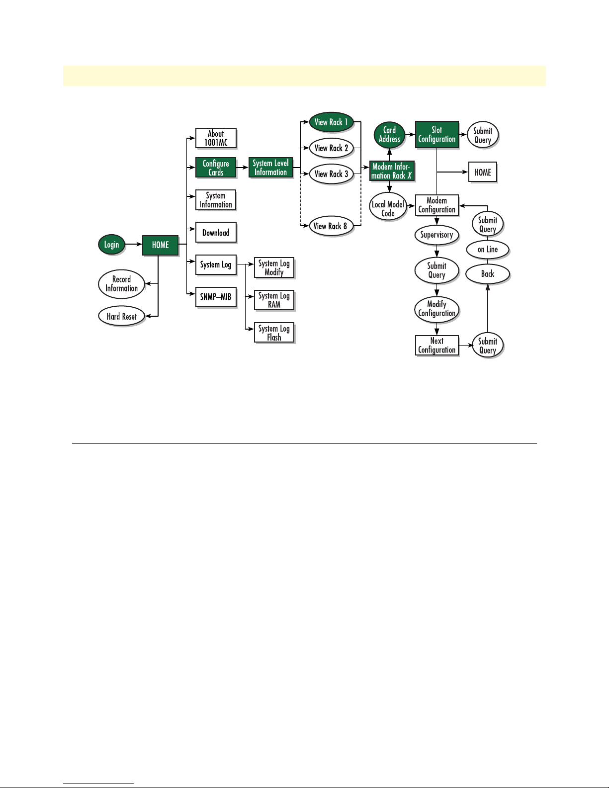
Model 1001MC Operations Guide 4 • Model 1092ARC management
Figure 27. Web page navigation to Slot Configuration page
For more information about items on the Slot Configuration page, see “Slot Configuration page MIB variables
description” on page 65.
Modem Information page MIB variables description
This section describes the MIB variables that are available on the Modem Information page.
Slots Available (totalConfigSlots)
Displays the number of configurable slots available in the rack.
Modems Installed (rackXCardsInstalled)
Displays the number of modem cards installed in the rack that the system has found.
Number of Power Supplies (rackXPowerSupplies)
This is where you specify the number of power supplies installed in the rack (this value determines the addressing
range for the rack). In the case of a redundant power supply system, you should set this variable to 2, this will
inform the Model 1001MC that there should be 2 power supplies in the system.
Rack Protection Mode
Note For Model 1095RC only.
If you want to protect all Model 1095RC rack cards installed in the current rack from being globally configured, select protected(1) from the pop-up menu, then click the
system configuration feature, refer to section “System Config” on page 259.
Modem Information page MIB variables description 57
Submit button. For more information about the
Page 58

Model 1001MC Operations Guide 4 • Model 1092ARC management
Note Setting the Rack Protection Mode to normal(0) will enable the rack to
receive new configurations through the global configuration command.
Submit button
After you have defined the number of power supplies installed in the rack and the rack protection mode, click
on the
Submit button to save the changes.
Power Supply 1 Status
Displays the current status of power supply 1 as one of the following:
• available(0)—The power supply is working normally.
• down(1)—If the status is shown as down, it means the 1001MC is unable to detect the power supply. This
status listing will also be highlighted in red.
• notInstalled(2)—The power supply has not been installed.
Power Supply 2 Status
Displays the current status of power supply 2 as one of the following:
• available(0)—The power supply is working normally.
• down(1)—If the status is shown as down, it means the 1001MC is unable to detect the power supply. This
status listing will also be highlighted in red.
• notInstalled(2)—The power supply has not been installed.
Clear Rack X Alarms (clearAlarms)
Click on this button to clear alarms for the current rack.
Note The System Log will still display the errors after the Clear Rack X
Alarms button is clicked.
Note The following information describes each column of the modem
table. Each table heading is a hyperlink to a help page that contains
information about the column.
Card Address (nmsSlotID)
This variable defines the address of the card. The Model 1001MC will poll the cards using the addresses listed
in the Card Address column. If a modem is found with the same address, it will be displayed in that row. The
address of the card is set up using the DIP-switches on the card. The address is also a hyperlink to the
1092ARC Configuration Slot page. This page can be used to set slot-specific information about the card.
Model
Line Status
The line status column on each View Rack page shows the current line status of each card. Keep in mind that
the more cards the 1001MC is managing, the longer it will take for the line status field to update. Displays the
status of the line. The following values can be displayed:
• startup(1)
• dataMode(2)—When the line status is dataMode(2), the units are linked-up and ready to send data.
Modem Information page MIB variables description 58
Page 59

Model 1001MC Operations Guide 4 • Model 1092ARC management
• testMode(3)
Warnings (warningCount)
This field displays the warnings that are associated with each modem installed in the system. When warnings
are present, this field will be highlighted in yellow and the number of warnings will be listed. For more information on the cause of the warning, you should view the System Log. Warnings will be highlighted in yellow
in the log. The warning for the slot can be erased in the
Note The System Log will still display the warnings even after the number is
Slot Configuration page.
cleared. The warning count listed in the Model 1001MC column is the
sum of all warnings for the system, including the individual modems.
Errors (errorCount)
This field displays the errors that are associated with each modem installed in the system. When errors are
present, this field will be highlighted in red and the number of errors will be listed. For more information on
the cause of the error, you should view the System Log. Errors will be highlighted in red in the log. The errors
for the slot can be erased in the
Note The System Log will still display the errors even after the number is
Slot Configuration page.
cleared. The error count listed in the Model 1001MC column is the
sum of all error s for the system, including the individual modems.
Local User Id (localUserID)
User supplied string that defines the NetLink modem installed in the rack. The string is stored in non-volatile
flash within the NetLink modem and is useful for hardware identification. If the address of the modem is
changed, the User ID will move to the new slot. The string can be up to 10 bytes long and can be changed or
reset within the
Slot Configuration page.
Local Model Code (localModelCode)
This column displays the model code of the NetLink modem installed at the specified address. The Model
Code is also a hyperlink into the configuration page for the NetLink modem and its remote unit. The model
code information is passed to the Model 1001MC after the card is placed online. The Model 1001MC is autosensing, meaning that when a card is found or lost, the information will automatically be updated in the system. You are not required to setup the Model Code information for each slot. When a card is removed from
the system, the Model Code will be erased and an error or warning will be displayed for the slot (this depends
on the settings in the
Slot Configuration page)
Remote User Id (remoteUserID)
User supplied string that defines the Customer Premise box at the far end of the link. The string is stored in
non-volatile flash within the CP unit. If the unit is moved, you ID will move to the new slot making it useful
for hardware identification. The string can be up to 10 bytes long and can be changed or reset within the
Configuration page.
Slot
Remote Model Code (remoteModelCode)
This column displays the model code of the Customer Premise NetLink modem at the far end of the link. This
information is communicated from the CP box over the link to the CO Rack Card unit. The NetLink mDSL
Modem Information page MIB variables description 59
Page 60

Model 1001MC Operations Guide 4 • Model 1092ARC management
rack card will then update the Model 1001MC. For this reason this information will not be available until after
the link is made between the two modems.
Protected
Note For Model 1095RC and Model 2701RC.
You can protect individual rack cards from being globally configured by setting the pop-up menu from normal(0) to protected(1). After you have set the protection option, if you are finished making changes to the cur-
rent rack card, click on the
Submit button (located at the right side of the rack card’s row in the table) to save
the changes.
Note Setting the protection to normal(0) will enable the rack card to receive
new configurations through the global configuration command.
Note After submitting the protection setting, you must click on the Record
Current Configuration button located on the HOME page to store
the configuration changes into memory (see “HOME” on page 228
for more information).
Local Circuit ID (localCircuitID)
The circuit ID is a 40-byte string that is stored in non-volatile flash within the Model 1001MC. This string
can be changed within the
mit Query button to input the string to the management system, you are required to select the Record Current
Configuration button on the Model 1001MC button on the Model 1001MC HOME page. This will store the
Configure Cards page or from the Slot Configuration page. After clicking the Sub-
information into flash making it available after a re-boot or power cycle.
Remote Circuit ID (remoteCircuitID)
The circuit ID is a 40-byte string that is stored in non-volatile flash within the Model 1001MC. This string
can be changed from the
Configure Cards web page or from the Slot Configuration page.
Submit button
Click the Submit button to input the changes to the management system. After clicking the Submit button, you
are required to select the
1001MC
HOME page. This will store the information into flash making it available after a re-boot or power cycle.
Note After submitting the remote circuit ID information, you must click
Record Current Configuration button on the Model 1001MC button on the Model
on the
Record Current Configuration button located on the HOME
page to store the configuration changes into memory (see “HOME”
on page 228 for more information).
Modem Information page MIB variables description 60
Page 61

Model 1001MC Operations Guide 4 • Model 1092ARC management
Model 1092 Configuration Slot page MIB variables description
This section describes the MIB variables that are available on the Model 1092 Configuration Slot page.
Model 1092A Model 1092 Configuration Slot (nmsSlotID)
Displays the address of the NetLink iDSL modem. The address is defined by the DIP-switch setting of S1 on
the rack card. The remote standalone unit has no address specified, but uses that address of the rack card that it
is connected to.
Line Status (lineStatusiDSL)
Displays the status of the line. There are three possible values that can be displayed:
• startup(1)
• dataMode(2)
• testMode(3)
When the line status is dataMode(2), the units are linked-up and ready to send data.
Processor Mode (processorModeiDSL)
Displays the status of the processor running on the NetLink-iDSL. There are four values that are significant to you:
• normal(0)—When the processor is in normal(0) mode, the NetLink iDSL modem is monitoring itself and
sending the status information to the Model 1001MC
• internalProcessing(1)—When the processor is in the internalProcessing(1) mode, it is either busy down-
loading code to the internal DSP or setting the data pump.
• negotiating(2)—When the processor is in the negotiating(2) mode, the card was just brought online and
the NetLink-iDSL is setting up the configuration parameters within the Model 1001MC
• lineDown(3)
At startup, all of the fields will be highlighted in yellow, signifying that they are not verified parameters. As the
NetLink-iDSL sets up the parameters, the highlighting disappears, signifying that the display matches the setting of the card.
Input Mode (mode1092A)
The following settings are available:
• onLine(0)
• superVisoryMode1)
To make configuration changes to the NetLink-iDSL modems, you must first set this bit to
superVisoryMode1). When the Input Mode is set to superVisoryMode1), the Modify Configuration hyperlink
will appear on the web page next to the
hyperlink. The
Model 1092A Configuration—Next Configuration page will appear (see section “Model 1092
Refresh Current Page hyperlink. Select the Modify Configuration
Configuration—Next Configuration page MIB variables description” on page 63 for more information). After
making configuration changes to the NetLink-iDSL modems in the Model 1092A
Update Configuration page,
return to this page and place the Input Mode variable back to onLine(0). This will notify the Model 1001MC
that the configuration has completed and will cause it to copy the new configuration into the NetLink-iDSL
Model 1092 Configuration Slot page MIB variables description 61
Page 62

Model 1001MC Operations Guide 4 • Model 1092ARC management
configuration space. If this is not done, the NetLink-iDSL will not recognize the configuration changes that
were made.
Model 1092 Configuration Slot page Configuration Status table description
The Configuration Status table shows the configuration for the set of units. There are columns for the local and
remote units. If a field is highlighted in yellow, it signifies one of two possible conditions:
• At start up, the Model 1001MC will display a default configuration for the card and all fields will be high-
lighted in yellow, notifying you that the information has not been verified. During the negotiation phase,
the NetLink-iDSL modem will update the configuration in the Model 1001MC with its last set of stored
parameters. As these fields are updated in the Model 1001MC, the yellow highlighting will disappear, signifying that the information has been updated. After the local and remote units are linked, the units will
begin updating the remote information in the table, and Line Status set to datamode(2).
• If a rack card is installed in the rack without a customer premise unit connected, the remote information
will be left as either none or highlighted in yellow, notifying you that the information has not been verified.
The following sections define the MIB variables that are shown in the Configuration Status table.
Model Code (localModelCode/remoteModelCode)
These variables display the local and remote models codes for the units that were found in the specified address.
DTE rate (dteRateiDSL)
This variable displays the DTE rate for the link. Because the NetLink-iDSL modems are symmetrical (same
rate in both direction), there is only one MIB variable that defines the DTE rate.
Clock Mode (Local-Remote)
This variable defines the clock mode for the NetLink modems. The display shows the Local clock mode (rack
card) and then the remote clock mode.
TM From DTE (dteTMiDSL/remotedteTMiDSL)
These MIB variables define whether you would like the modems to accept test mode requests from the DTE
that is connected. In normal applications this should be set to disable(1). When the application is using rear
cards or interface modules that do not have loop back ability from the DTE, such as the IM2RC/IA Ethernet
rear card, this variable must be set to disable(1). In most situations, if a DTE test mode is required, it should be
enable only during the time that the test is needed.
HW Test Mode (testModeIndiDSL/remotetestModeIndiDSL)
These read-only variables notify you that the specified unit has been placed into a test mode through the hardware. This could have been done either through the front panel switches or from the DTE (if the TM from DTE
is enabled). When a test mode is displayed, the field will be highlighted in blue to give you quick notification.
SW Test Mode (testModeSetiDSL/remotetestModeSetiDSL)
These variables notify you that the specified unit has been placed into a test mode through the management
station. The management can place a unit into a test mode within the Model 1092A Update Configuration
page explained in more detail below.
Model 1092 Configuration Slot page MIB variables description 62
Page 63

Model 1001MC Operations Guide 4 • Model 1092ARC management
Software Rev (softVersioniDSL/remotesoftversioniDSL)
These read-only MIB variables display the current version of code that is running in the NetLink-iDSL
modems. Check the Download page to see if the Model 1001MC has a newer version of code available for
downloading. Through the download web page, you can update the software that is running in the NetLinkiDSL rack card. You can also update the software in the NetLink stand alone unit through the front panel control port on the unit.
Model 1092 Configuration—Next Configuration page MIB
variables description
The Model 1092 Configuration—Next Configuration page enables you to update the configuration of the
1092ARC NetLink-iDSL modems that are installed in the system. After making changes to the configuration on
this page, select Back to return to the
Mode, and finally, select
Note If the NetLink-iDSL modems are not connected, and changes made
Submit Query to send the new information to the Model 1001MC over the network.
to the remote configuration will be lost after the units link-up. All
parameters in the Local column can be changed at any time.
The following sections describes the MIB variables that are available on the Model 1092 Configuration—Next
Configuration page.
Model 1092 Configuration Slot page, then select onLine as the Input
Card Address (nmsSlotID)
Displays the address of the selected NetLink-iDSL modem.
Line Status (lineStatusiDSL)
This variable displays the status of the line. There are three possible values that can be displayed:
• startup(1)
• dataMode(2)—In this mode, the units are linked-up and ready to send data
• testMode(3)
Processor Mode (processorModeiDSL)
This variable displays the status of the processor running on the NetLink-iDSL. There are four values that are
significant to you:
• normal(0)—When the processor is in normal(0) mode, the NetLink - iDSL modem is monitoring itself
and sending the status information to the Model 1001MC
• internalProcessing(1)—When the processor is in the internalProcessing(1) mode, it is either busy down-
loading code to the internal DSP or setting the data pump.
• negotiating(2)—When the processor is in the negotiating(2) mode, the card was just brought online and
the NetLink-iDSL is setting up the configuration parameters within the Model 1001MC.
• lineDown(3).
Model 1092 Configuration—Next Configuration page MIB variables description 63
Page 64

Model 1001MC Operations Guide 4 • Model 1092ARC management
At startup, all of the fields will be highlighted in yellow, signifying that they are not verified parameters. As the
NetLink-iDSL sets up the parameters, the highlighting disappears, signifying that the display matches the setting of the card.
Local Software Rev (softVersioniDSL)
These read-only MIB variable displays the current version of code that is running in the NetLink-iDSL rack
card modem. You should check the download web page to see if the Model 1001MC has a newer version of
code available for downloading. Through the download web page, you can update the software that is running
in the NetLink-iDSL rack card.
Remote Software Rev (remotesoftversioniDSL)
These read-only MIB variable displays the current version of code that is running in the NetLink-iDSL Customer Premise modem. You can update the software in the NetLink stand alone unit through the front panel
control port on the unit. For more information regarding software downloads for standalone units, visit the
Patton Electronics web site at www.patton.com.
Next Configuration table
This table shows the configurable MIB variables for the set of units. There are column for the local and remote
units. In some cases a single variable applies to both the local and remote unit. In this case, a single configuration field is made available in the Local column and the Remote column is made a read-only field. After
changes are made, select the
Submit Query button at the bottom of the table and then place the Input Mode
back to onLine(0) in the Model 1092 Configuration page.
The following sections explain the MIB variables that are shown in the Next Configuration table.
DTE rate (dteRateiDSL)
This variable displays the DTE rate for the link. Because the NetLink-iDSL modems are symmetrical (same
rate in both direction), there is only MIB variable that defines the DTE rate. The Customer Premise box will
automatically update its' configuration to the DTE rate that is set here.
Clock Mode (Local-Remote)
This variable defines the clock mode for the NetLink modems. The display shows the Local clock mode (rack
card) and then the remote clock mode as a single variable in the Local column. The Remote column displays a
read only field showing the remote units clocking mode. This was done to avoid an illegal configuration of the
NetLink-iDSL modems. For instance, both units CAN NOT be set to internal clock. The options list all possible clocking combinations.
TM From DTE (dteTMiDSL/remotedteTMiDSL)
These MIB variables define whether you would like the modems to accept test mode requests from the DTE
that is connected. In normal applications this should be set to disable(1). When the application is using rear
cards or interface modules that do not have loop back ability from the DTE, such as the IM2RC/IA Ethernet
rear card, this variable must be set to disable(1). In most situations, if a DTE test mode is required, it should be
enable only during the time that the test is needed.
Test Mode (testModeSetiDSL/remotetestModeSetiDSL)
These variables allow you to place the NetLink-iDSL rack card into test modes. For more information on the
test modes, please see the NetLink-iDSL Test Modes section below.
Model 1092 Configuration—Next Configuration page MIB variables description 64
Page 65

Model 1001MC Operations Guide 4 • Model 1092ARC management
Submit Query button
After making configuration changes, select the Back link, then select onLine, and finally, select Submit Query.
This will submit all the configuration information to the Model 1001MC. After this, the information is stored
in volatile RAM until you place the Input Mode to onLine(0). This will tell the 1001MC to copy all of the
configuration information into the NetLink-iDSL configuration space.
Clear Changes
Once configuration changes have been made and you have selected the Submit Query button, if you decide
not to implement these changes, select the
Clear Changes button. This will set the configuration back to the
settings that were there when this page was entered.
Set Default Configuration
Selecting this button will place the default configuration into the Next Configuration table.
Slot Configuration page MIB variables description
This section describes the MIB variables that are available on the Slot Configuration page. From the Modem
Information page, the address column creates a list of hyperlinks to the Slot Configuration page associated with
the specified address. The
tem and how the system treats the slot in the case of errors and warning.
Slot Configuration page can be used to set slot-specific information related to the sys-
Note The information contained here is also available in the Model
1001MC manual and is listed here for ease of use.
Card Address (nmsSlotID)
Displays the address of the card.
Local Model Code (localModelCode)
Displays the model code of the NetLink modem installed at the specified address.
View Rack X hyperlink
Click on the View Rack X link to display the Modem Information Rack X window (see section “Modem Infor-
mation Rack X” on page 239 for more information).
Card Identification Information
Local User Id (localUserID)
User supplied string that defines the NetLink modem installed in the rack. The string is stored in non-volatile
flash within the NetLink modem and is useful for hardware identification. If the address of the modem is
changed, the User ID will move to the new slot. The string can be up to 10 bytes long and can be changed or
reset within this page.
Remote User Id (remoteUserID)
User supplied string that defines the Customer Premise box at the far end of the link. The string is stored in
non-volatile flash within the CP unit. If the unit is moved, the User ID will move to the new slot making it
useful for hardware identification. The string can be up to 10 bytes long and can be changed or reset within
this page.
Slot Configuration page MIB variables description 65
Page 66

Model 1001MC Operations Guide 4 • Model 1092ARC management
Local Circuit ID (localCircuitID)
The circuit ID is a 40-byte string that is stored in non-volatile flash within the Model 1001MC.
Remote Circuit ID (remoteCircuitID)
The circuit ID is a 40-byte string that is stored in non-volatile flash within the Model 1001MC.
Alarm Information
Clear Slot Alarms (resetStatus)
Selecting this push button erases the alarms (errors and warning) associated with the specified slot.
Note The errors and warning will still be listed in the System Log.
Hardware Reset (resetStatus)
Selecting this push button will force the associated modem to perform a hardware reset.
Card Lost Indication (cardLostIndication)
This variable allows you to choose what type of indication will be made if a modem is removed from the management system. Three choices are available:
• Error
• Warning
• None
Line Down Indication (lineDownIndication)
This variable allows you to choose what type of indication will be made if a modem reports a line down scenario. Three choices are available:
• Error
• Warning
• None
Note Line Down Indication must be set to error(2) line up and line down
SNMP trap messages to be sent.
Slot Configuration page MIB variables description 66
Page 67

Chapter 5 Model 1094ARC management
Chapter contents
Introduction..........................................................................................................................................................69
NetLink-NMS description ..............................................................................................................................69
Configuration and management ............................................................................................................................69
Displaying the Modem Information page .......................................................................................................70
Displaying the Model 1094 Configuration Slot page ......................................................................................72
Making configuration changes to your 1094ARC NetLink modem ..........................................................73
Displaying the Model 1094 Configuration—Next Configuration page ...........................................................74
Displaying the Slot Configuration page ..........................................................................................................76
Displaying the Download page .......................................................................................................................77
Modem Information page MIB variables description.............................................................................................78
Slots Available (totalConfigSlots) ....................................................................................................................78
Modems Installed (rackXCardsInstalled) .........................................................................................................78
Number of Power Supplies (rackXPowerSupplies) ..........................................................................................78
Rack Protection Mode ....................................................................................................................................78
Submit button ................................................................................................................................................79
Power Supply 1 Status ....................................................................................................................................79
Power Supply 2 Status ....................................................................................................................................79
Clear Rack X Alarms (clearAlarms) .................................................................................................................79
Card Address (nmsSlotID) ..............................................................................................................................79
Line Status ......................................................................................................................................................79
Warnings (warningCount) ..............................................................................................................................80
Errors (errorCount) .........................................................................................................................................80
Local User Id (localUserID) ............................................................................................................................80
Local Model Code (localModelCode) .............................................................................................................80
Remote User Id (remoteUserID) .....................................................................................................................80
Remote Model Code (remoteModelCode) ......................................................................................................80
Protected .........................................................................................................................................................81
Local Circuit ID (localCircuitID) ...................................................................................................................81
Remote Circuit ID (remoteCircuitID) ............................................................................................................81
Submit button ................................................................................................................................................81
Model 1094 Configuration Slot page MIB variables description............................................................................81
Model 1094A Model 1094 Configuration Slot (nmsSlotID) ...........................................................................81
Line Status (lineStatus1094) ...........................................................................................................................82
Processor Mode (processorMode1094) ...........................................................................................................82
Input Mode (mode1094) ................................................................................................................................82
Model 1094 Configuration Slot page Configuration Status table description ..................................................82
Model Code (localModelCode/remoteModelCode) ..................................................................................83
DTE rate (dteRate1094) ...........................................................................................................................83
Clock Mode (Local-Remote) .....................................................................................................................83
67
Page 68

Model 1001MC Operations Guide 5 • Model 1094ARC management
TM From DTE (dteTM1094/remotedteTM1094) ...................................................................................83
HW Test Mode (testModeInd1094/remotetestModeInd1094) .................................................................83
SW Test Mode (testModeSet1094/remotetestModeSet1094) ...................................................................83
Software Rev (softVersion1094/remotesoftversion1094) ...........................................................................83
Model 1094 Configuration—Next Configuration page MIB variables description ................................................84
Card Address (nmsSlotID) ..............................................................................................................................84
Line Status (lineStatus1094) ...........................................................................................................................84
Processor Mode (processorMode1094) ...........................................................................................................84
Local Software Rev (softVersion1094) ............................................................................................................84
Remote Software Rev (remotesoftversion1094) ...............................................................................................85
Next Configuration table ................................................................................................................................85
DTE rate (dteRate1094) ...........................................................................................................................85
Clock Mode (Local-Remote) .....................................................................................................................85
Tx Data Sample Point (txdEdge1095/remotetxdEdge1095) ......................................................................85
TM From DTE (dteTM1094/remotedteTM1094) ...................................................................................85
Test Mode (testModeSet1094/remotetestModeSet1094) ..........................................................................85
Submit Query button ................................................................................................................................85
Clear Changes ...........................................................................................................................................86
Set Default Configuration .........................................................................................................................86
Slot Configuration page MIB variables description................................................................................................86
Card Address (nmsSlotID) ..............................................................................................................................86
Local Model Code (localModelCode) .............................................................................................................86
View Rack X hyperlink ...................................................................................................................................86
Card Identification Information ......................................................................................................................86
Local User Id (localUserID) ......................................................................................................................86
Remote User Id (remoteUserID) ...............................................................................................................86
Local Circuit ID (localCircuitID) .............................................................................................................86
Remote Circuit ID (remoteCircuitID) ......................................................................................................87
Alarm Information ..........................................................................................................................................87
Clear Slot Alarms (resetStatus) ..................................................................................................................87
Hardware Reset (resetStatus) .....................................................................................................................87
Card Lost Indication (cardLostIndication) ................................................................................................87
Line Down Indication (lineDownIndication) ............................................................................................87
Using the Download page to upgrade 1094ARC software .....................................................................................87
68
Page 69

Model 1001MC Operations Guide 5 • Model 1094ARC management
Introduction
This chapter describes managing a Model 1094ARC NetLink HDSL modem using the Model 1001MC
NetLink-NMS internal HTTP/HTML web engine and a standard web browser. This chapter is meant to be
used in addition to the manual that came with your unit.
NetLink-NMS description
Specifically designed for use in the Patton NetLink system, when the NetLink HDSL is coupled with the Model
1001MC NetLink-NMS and the Patton Model 1001 rack system, the modem is fully SNMP manageable.
SNMP management can be performed on both the local and remote units using a standard SNMP network management station (NMS) or by using a standard web browser and the Model 1001MC's built-in web server. You
can view and change configuration variables, view statistical variables, and view error and warning indications.
Configuration and management
This section describes the configuration and management of your NetLink HDSL modems using a Model
1001MC NetLink-NMS with built in HTTP/HTML web server. If you plan to manage your units using a
standard network management station you can download the Patton Enterprise MIBs either through the
SNMP web page on the Model 1001MC or obtain them from the Patton web site at www.patton.com.
The following pages are used to configure and manage the Model 1094ARC:
• Modem Information page: This page displays a list of the cards that are installed in your system and a quick
view of any errors or warnings associated with your modems (see section “Displaying the Modem Informa-
tion page” on page 70)
• Model 1094 Configuration Slot page: This page (along with the Model 1094 Configuration—Next Config-
uration page) enables you to make configuration changes to the Model 1094A and the remote CPE box (see
section “Displaying the Model 1094 Configuration Slot page” on page 72)
• Model 1094 Configuration—Next Configuration page: This page (along with the Model 1094 Configura-
tion Slot page) enables you to update configuration of modems installed in the system (see “Displaying the
Model 1094 Configuration—Next Configuration page” on page 74)
• Slot Configuration page: This page can be used to set slot-specific information related to the system and how
the system treats the slot in the case of errors or warnings (see section “Displaying the Model 1094 Configu-
ration Slot page” on page 72)
• Download page: This page is where you can download the latest version of 1001MC and 1094ARC soft-
ware (see section “Displaying the Download page” on page 77)
Note For information about other Model 1001MC pages, refer to
chapter 10, “HTTP/HTML web page reference” on page 220.
Introduction 69
Page 70

Model 1001MC Operations Guide 5 • Model 1094ARC management
Displaying the Modem Information page
The Modem Information page (see figure 28) displays the cards installed in the system and a quick view of any
errors or warnings associated with your modems.
Figure 28. Modem Information page for the Model 1094ARC
Starting from the HOME page, to access the Modem Information page for the 1094ARC, click on the following
links: Configure Cards > View Rack 1. Figure 29 on page 71 shows the web page navigation required to get to
this area of the system. For more information about items on the
Modem Information page, see “Displaying the
Slot Configuration page” on page 76.
Configuration and management 70
Page 71

Model 1001MC Operations Guide 5 • Model 1094ARC management
Figure 29. Web page navigation to Modem Information page
Configuration and management 71
Page 72

Model 1001MC Operations Guide 5 • Model 1094ARC management
Displaying the Model 1094 Configuration Slot page
The Model 1094 Configuration Slot page (see figure 30) enables you to make configuration changes to the
Model 1094A and the remote CPE box. When the page displays, the unit is set to the onLine state and the current configuration is displayed.
Figure 30. Model 1094 Configuration Slot page
Starting from the HOME page, to access the Model 1094 Configuration Slot page for the 1094ARC, click on
the following links: Configure Cards > View Rack 1 > Local_Model_Code for the 1094ARC you wish to manage
(in the example shown in figure 30, the 1094ARC was installed in slot 11). Figure 31 on page 73 shows the web
page navigation required to get to this area of the system.
Configuration and management 72
Page 73

Model 1001MC Operations Guide 5 • Model 1094ARC management
Figure 31. Web page navigation to Model 1094 Configuration Slot page
Making configuration changes to your 1094ARC NetLink modem
Do use the following to make configuration changes to your NetLink modem.
Note You must be logged in as superuser to perform the following procedure.
1. With the Model 1094 Configuration Slot page displayed, change the Input Mode (see figure 30) to super-
VisoryMode. The Modify Configuration hyperlink will appear.
2. Click on the Modify Configuration hyperlink to display the Model 1094A Next Configuration page.
3. Make your configuration changes or select the Set Default Configuration button.
4. Select the Submit Query button to place the changes into the 1001MC’s temporary memory. If you decide
that you do not want your changes implemented, you can select the
Clear Changes button.
5. Select the Back hyperlink to return to the Model 1094 Configuration Slot page.
6. Change the Input Mode back to onLine and select the Submit Query button. When the unit returns to the
online state, the 1094A will begin implementing the configuration changes.
Note The variables that you changed are now highlighted in yellow. After the
1094A processes the new information, the highlighting will be removed.
For more information about items on the Model 1094 Configuration Slot page, see “Model 1094 Configura-
tion Slot page MIB variables description” on page 81.
Configuration and management 73
Page 74
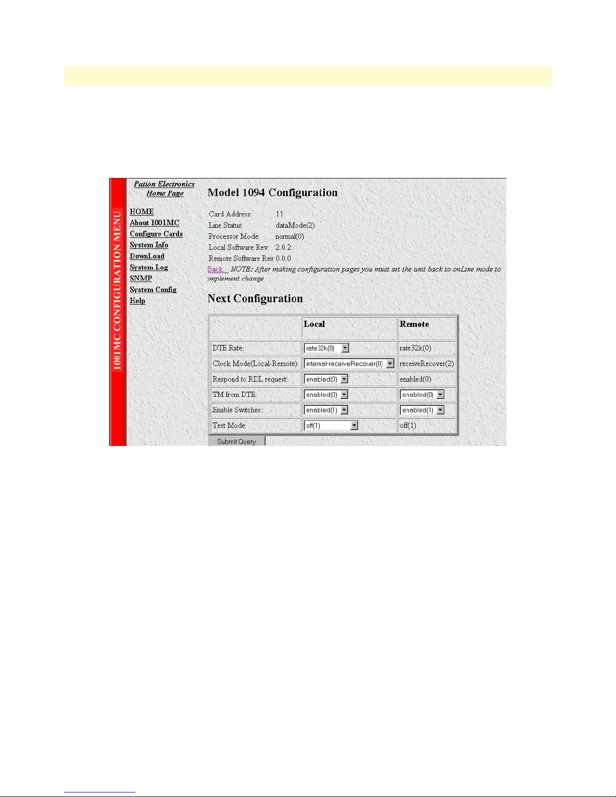
Model 1001MC Operations Guide 5 • Model 1094ARC management
Displaying the Model 1094 Configuration—Next Configuration page
The Model 1094 Configuration—Next Configuration page (see figure 32) enables you to make configuration
changes to the Model 1094A and the remote CPE box. When the page displays, the unit is set to the onLine
state and the current configuration is displayed.
Figure 32. Model 1094 Configuration—Next Configuration page
Starting from the HOME page, to access the Model 1094 Configuration—Next Configuration page for the
1094ARC, click on the following links: Configure Cards > View Rack 1 > Local_Model_Code for the 1094ARC
you wish to manage > Modify Configuration (you first have to change input mode from onLine to superVisory-
Mode. Figure 33 on page 75 shows the web page navigation required to get to this area of the system.
For more information about items on the Model 1094 Configuration—Next Configuration page, see “Model
1094 Configuration—Next Configuration page MIB variables description” on page 84.
Configuration and management 74
Page 75

Model 1001MC Operations Guide 5 • Model 1094ARC management
Figure 33. Web page navigation to Model 1094 Configuration—Next Configuration page
Configuration and management 75
Page 76
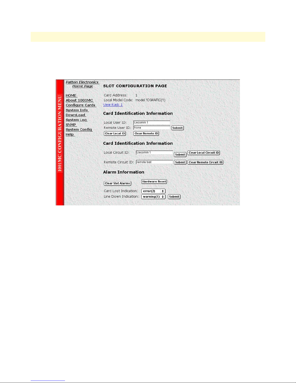
Model 1001MC Operations Guide 5 • Model 1094ARC management
Displaying the Slot Configuration page
The Slot Configuration page (see figure 34) is used to set slot-specific information related to the system and how
the system treats that slot in the case of errors or warnings.
Figure 34. Slot Configuration page
Starting from the HOME page, to access the Slot Configuration page for the 1094ARC, click on the following
links: Configure Cards > View Rack 1 > Card_Address for the 1094ARC you wish to manage (in the example
shown in figure 34, the 1094ARC was installed in slot 1). Figure 35 on page 77 shows the web page navigation
required to get to this area of the system.
Configuration and management 76
Page 77
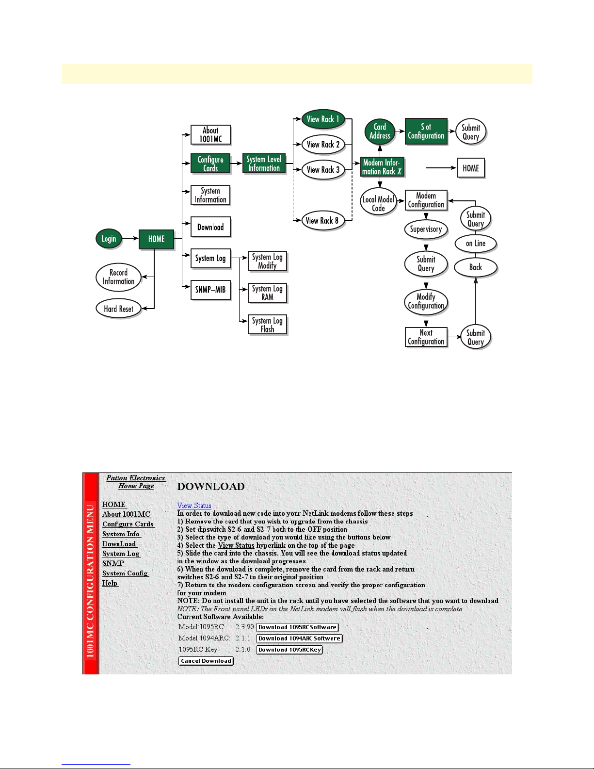
Model 1001MC Operations Guide 5 • Model 1094ARC management
Figure 35. Web page navigation to Slot Configuration page
For more information about items on the Slot Configuration page, see “Slot Configuration page MIB variables
description” on page 86.
Displaying the Download page
The Download page (see figure 36) is where you can download the latest version of 1001MC and
1094ARC software.
Configuration and management 77
Figure 36. Download page
Page 78
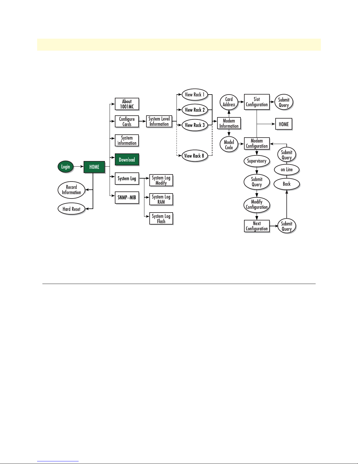
Model 1001MC Operations Guide 5 • Model 1094ARC management
Starting from the HOME page, to access the Download page for the 1094ARC, click on the Download link.
Figure 37 shows the web page navigation required to get to this area of the system.
Figure 37. Web page navigation to Download page
For more information about items on the Slot Configuration page, see “Using the Download page to upgrade
1094ARC software” on page 87.
Modem Information page MIB variables description
This section describes the MIB variables that are available on the Modem Information page.
Slots Available (totalConfigSlots)
Displays the number of configurable slots available in the rack.
Modems Installed (rackXCardsInstalled)
Displays the number of modem cards installed in the rack that the system has found.
Number of Power Supplies (rackXPowerSupplies)
This is where you specify the number of power supplies installed in the rack (this value determines the addressing
range for the rack). In the case of a redundant power supply system, you should set this variable to 2, this will
inform the Model 1001MC that there should be 2 power supplies in the system.
Rack Protection Mode
If you want to protect all Model 1095RC rack cards installed in the current rack from being globally configured, select protected(1) from the pop-up menu, then click the
system configuration feature, refer to section “System Config” on page 259.
Submit button. For more information about the
Modem Information page MIB variables description 78
Page 79

Model 1001MC Operations Guide 5 • Model 1094ARC management
Note Setting the Rack Protection Mode to normal(0) will enable the rack to
receive new configurations through the global configuration command.
Submit button
After you have defined the number of power supplies installed in the rack and the rack protection mode, click
on the
Submit button to save the changes.
Power Supply 1 Status
Displays the current status of power supply 1 as one of the following:
• available(0)—The power supply is working normally.
• down(1)—If the status is shown as down, it means the 1001MC is unable to detect the power supply. This
status listing will also be highlighted in red.
• notInstalled(2)—The power supply has not been installed.
Power Supply 2 Status
Displays the current status of power supply 2 as one of the following:
• available(0)—The power supply is working normally.
• down(1)—If the status is shown as down, it means the 1001MC is unable to detect the power supply. This
status listing will also be highlighted in red.
• notInstalled(2)—The power supply has not been installed.
Clear Rack X Alarms (clearAlarms)
Click on this button to clear alarms for the current rack.
Note The System Log will still display the errors after the Clear Rack X
Alarms button is clicked.
Note The following information describes each column of the modem
table. Each table heading is a hyperlink to a help page that contains
information about the column.
Card Address (nmsSlotID)
This variable defines the address of the card. The Model 1001MC will poll the cards using the addresses listed
in the Card Address column. If a modem is found with the same address, it will be displayed in that row. The
address of the card is set up using the DIP-switches on the card. The address is also a hyperlink to the
1095 Configuration Slot page. This page can be used to set slot-specific information about the card.
Model
Line Status
The line status column on each View Rack page shows the current line status of each card. Keep in mind that
the more cards the 1001MC is managing, the longer it will take for the line status field to update. Displays the
status of the line. The following values can be displayed:
• startup(1)
• dataMode(2)—When the line status is dataMode(2), the units are linked-up and ready to send data.
Modem Information page MIB variables description 79
Page 80

Model 1001MC Operations Guide 5 • Model 1094ARC management
• testMode(3)
Warnings (warningCount)
This field displays the warnings that are associated with each modem installed in the system. When warnings
are present, this field will be highlighted in yellow and the number of warnings will be listed. For more information on the cause of the warning, you should view the System Log. Warnings will be highlighted in yellow
in the log. The warning for the slot can be erased in the
Note The System Log will still display the warnings even after the number is
Slot Configuration page.
cleared. The warning count listed in the Model 1001MC column is the
sum of all warnings for the system, including the individual modems.
Errors (errorCount)
This field displays the errors that are associated with each modem installed in the system. When errors are
present, this field will be highlighted in red and the number of errors will be listed. For more information on
the cause of the error, you should view the System Log. Errors will be highlighted in red in the log. The errors
for the slot can be erased in the
Note The System Log will still display the errors even after the number is
Slot Configuration page.
cleared. The error count listed in the Model 1001MC column is the
sum of all error s for the system, including the individual modems.
Local User Id (localUserID)
User supplied string that defines the NetLink modem installed in the rack. The string is stored in non-volatile
flash within the NetLink modem and is useful for hardware identification. If the address of the modem is
changed, the User ID will move to the new slot. The string can be up to 10 bytes long and can be changed or
reset within the
Slot Configuration page.
Local Model Code (localModelCode)
This column displays the model code of the NetLink modem installed at the specified address. The Model
Code is also a hyperlink into the configuration page for the NetLink modem and its remote unit. The model
code information is passed to the Model 1001MC after the card is placed online. The Model 1001MC is autosensing, meaning that when a card is found or lost, the information will automatically be updated in the system. You are not required to setup the Model Code information for each slot. When a card is removed from
the system, the Model Code will be erased and an error or warning will be displayed for the slot (this depends
on the settings in the
Slot Configuration page)
Remote User Id (remoteUserID)
User supplied string that defines the Customer Premise box at the far end of the link. The string is stored in
non-volatile flash within the CP unit. If the unit is moved, you ID will move to the new slot making it useful
for hardware identification. The string can be up to 10 bytes long and can be changed or reset within the
Configuration page.
Slot
Remote Model Code (remoteModelCode)
This column displays the model code of the Customer Premise NetLink modem at the far end of the link. This
information is communicated from the CP box over the link to the CO Rack Card unit. The NetLink mDSL
Modem Information page MIB variables description 80
Page 81

Model 1001MC Operations Guide 5 • Model 1094ARC management
rack card will then update the Model 1001MC. For this reason this information will not be available until after
the link is made between the two modems.
Protected
You can protect individual rack cards from being globally configured by setting the pop-up menu from normal(0) to protected(1). After you have set the protection option, if you are finished making changes to the cur-
rent rack card, click on the
Submit button (located at the right side of the rack card’s row in the table) to save
the changes.
Note Setting the protection to normal(0) will enable the rack card to receive
new configurations through the global configuration command.
Note After submitting the protection setting, you must click on the Record
Current Configuration
button located on the HOME page to store
the configuration changes into memory (see “HOME” on page 228
for more information).
Local Circuit ID (localCircuitID)
The circuit ID is a 40-byte string that is stored in non-volatile flash within the Model 1001MC. This string
can be changed within the
mit Query button to input the string to the management system, you are required to select the Record Current
Configuration button on the Model 1001MC button on the Model 1001MC HOME page. This will store the
Configure Cards page or from the Slot Configuration page. After clicking the Sub-
information into flash making it available after a re-boot or power cycle.
Remote Circuit ID (remoteCircuitID)
The circuit ID is a 40-byte string that is stored in non-volatile flash within the Model 1001MC. This string
can be changed from the
Configure Cards web page or from the Slot Configuration page.
Submit button
Click the Submit button to input the changes to the management system. After clicking the Submit button, you
are required to select the
1001MC
HOME page. This will store the information into flash making it available after a re-boot or power cycle.
Note After submitting the remote circuit ID information, you must click
Record Current Configuration button on the Model 1001MC button on the Model
on the
Record Current Configuration button located on the HOME
page to store the configuration changes into memory (see “HOME”
on page 228 for more information).
Model 1094 Configuration Slot page MIB variables description
This section describes the MIB variables that are available on the Model 1094 Configuration Slot page.
Model 1094A Model 1094 Configuration Slot (nmsSlotID)
Displays the address of the NetLink HDSL modem. The address is defined by the DIP-switch setting of S1 on
the rack card. The remote standalone unit has no address specified, but uses that address of the rack card that it
is connected to.
Model 1094 Configuration Slot page MIB variables description 81
Page 82

Model 1001MC Operations Guide 5 • Model 1094ARC management
Line Status (lineStatus1094)
Displays the status of the line. There are three possible values that can be displayed:
• startup(1)
• dataMode(2)
• testMode(3)
When the line status is dataMode(2), the units are linked-up and ready to send data.
Processor Mode (processorMode1094)
Displays the status of the processor running on the NetLink-HDSL. There are four values that are significant to
you:
• normal(0)—When the processor is in normal(0) mode, the NetLink HDSL modem is monitoring itself
and sending the status information to the Model 1001MC
• internalProcessing(1)—When the processor is in the internalProcessing(1) mode, it is either busy down-
loading code to the internal DSP or setting the data pump.
• negotiating(2)—When the processor is in the negotiating(2) mode, the card was just brought online and
the NetLink-HDSL is setting up the configuration parameters within the Model 1001MC
• lineDown(3)
At startup, all of the fields will be highlighted in yellow, signifying that they are not verified parameters. As the
NetLink-HDSL sets up the parameters, the highlighting disappears, signifying that the display matches the setting of the card.
Input Mode (mode1094)
The following settings are available:
• onLine(0)
• superVisoryMode1)
To make configuration changes to the NetLink-HDSL modems, you must first set this bit to
superVisoryMode1). When the Input Mode is set to superVisoryMode1), the Modify Configuration hyperlink
will appear on the web page next to the
hyperlink. The
Model 1094A Configuration—Next Configuration page will appear (see section “Model 1094
Refresh Current Page hyperlink. Select the Modify Configuration
Configuration—Next Configuration page MIB variables description” on page 84 for more information). After
making configuration changes to the NetLink-HDSL modems in the Model 1094A
Update Configuration
page, return to this page and place the Input Mode variable back to onLine(0). This will notify the Model
1001MC that the configuration has completed and will cause it to copy the new configuration into the
NetLink-HDSL configuration space. If this is not done, the NetLink-HDSL will not recognize the configuration changes that were made.
Model 1094 Configuration Slot page Configuration Status table description
The Configuration Status table shows the configuration for the set of units. There are columns for the local and
remote units. If a field is highlighted in yellow, it signifies one of two possible conditions:
• At start up, the Model 1001MC will display a default configuration for the card and all fields will be high-
lighted in yellow, notifying you that the information has not been verified. During the negotiation phase,
Model 1094 Configuration Slot page MIB variables description 82
Page 83

Model 1001MC Operations Guide 5 • Model 1094ARC management
the NetLink-HDSL modem will update the configuration in the Model 1001MC with its last set of stored
parameters. As these fields are updated in the Model 1001MC, the yellow highlighting will disappear, signifying that the information has been updated. After the local and remote units are linked, the units will
begin updating the remote information in the table, and Line Status set to datamode(2).
• If a rack card is installed in the rack without a customer premise unit connected, the remote information
will be left as either none or highlighted in yellow, notifying you that the information has not been verified.
The following sections define the MIB variables that are shown in the Configuration Status table.
Model Code (localModelCode/remoteModelCode)
These variables display the local and remote models codes for the units that were found in the specified address.
DTE rate (dteRate1094)
This variable displays the DTE rate for the link. Because the NetLink-HDSL modems are symmetrical (same
rate in both direction), there is only one MIB variable that defines the DTE rate.
Clock Mode (Local-Remote)
This variable defines the clock mode for the NetLink modems. The display shows the Local clock mode (rack
card) and then the remote clock mode.
TM From DTE (dteTM1094/remotedteTM1094)
These MIB variables define whether you would like the modems to accept test mode requests from the DTE
that is connected. In normal applications this should be set to disable(1). When the application is using rear
cards or interface modules that do not have loop back ability from the DTE, such as the IM2RC/IA Ethernet
rear card, this variable must be set to disable(1). In most situations, if a DTE test mode is required, it should be
enable only during the time that the test is needed.
HW Test Mode (testModeInd1094/remotetestModeInd1094)
These read-only variables notify you that the specified unit has been placed into a test mode through the hardware. This could have been done either through the front panel switches or from the DTE (if the TM from DTE
is enabled). When a test mode is displayed, the field will be highlighted in blue to give you quick notification.
SW Test Mode (testModeSet1094/remotetestModeSet1094)
These variables notify you that the specified unit has been placed into a test mode through the management
station. The management can place a unit into a test mode within the Model 1094A Update Configuration
page explained in more detail below.
Software Rev (softVersion1094/remotesoftversion1094)
These read-only MIB variables display the current version of code that is running in the NetLink-HDSL
modems. Check the Download page to see if the Model 1001MC has a newer version of code available for
downloading. Through the download web page, you can update the software that is running in the NetLinkHDSL rack card. You can also update the software in the NetLink stand alone unit through the front panel
control port on the unit.
Model 1094 Configuration Slot page MIB variables description 83
Page 84

Model 1001MC Operations Guide 5 • Model 1094ARC management
Model 1094 Configuration—Next Configuration page MIB
variables description
The Model 1094 Configuration—Next Configuration page enables you to update the configuration of the
1094ARC NetLink-HDSL modems that are installed in the system. After making changes to the configuration
on this page, select
Mode, and finally, select
The following sections describes the MIB variables that are available on the Model 1094 Configuration—Next
Configuration page.
Card Address (nmsSlotID)
Displays the address of the selected NetLink-HDSL modem.
Line Status (lineStatus1094)
This variable displays the status of the line. There are three possible values that can be displayed:
Back to return to the Model 1094 Configuration Slot page, then select onLine as the Input
Submit Query to send the new information to the Model 1001MC over the network.
Note If the NetLink-HDSL modems are not connected, and changes made
to the remote configuration will be lost after the units link-up. All
parameters in the Local column can be changed at any time.
• startup(1)
• dataMode(2)—In this mode, the units are linked-up and ready to send data
• testMode(3)
Processor Mode (processorMode1094)
This variable displays the status of the processor running on the NetLink-HDSL. There are four values that are
significant to you:
• normal(0)—When the processor is in normal(0) mode, the NetLink - HDSL modem is monitoring itself
and sending the status information to the Model 1001MC
• internalProcessing(1)—When the processor is in the internalProcessing(1) mode, it is either busy down-
loading code to the internal DSP or setting the data pump.
• negotiating(2)—When the processor is in the negotiating(2) mode, the card was just brought online and
the NetLink-HDSL is setting up the configuration parameters within the Model 1001MC.
• lineDown(3).
At startup, all of the fields will be highlighted in yellow, signifying that they are not verified parameters. As the
NetLink-HDSL sets up the parameters, the highlighting disappears, signifying that the display matches the setting of the card.
Local Software Rev (softVersion1094)
These read-only MIB variable displays the current version of code that is running in the NetLink-HDSL rack
card modem. You should check the download web page to see if the Model 1001MC has a newer version of
code available for downloading. Through the download web page, you can update the software that is running
in the NetLink-HDSL rack card.
Model 1094 Configuration—Next Configuration page MIB variables description 84
Page 85

Model 1001MC Operations Guide 5 • Model 1094ARC management
Remote Software Rev (remotesoftversion1094)
These read-only MIB variable displays the current version of code that is running in the NetLink-HDSL Customer Premise modem. You can update the software in the NetLink stand alone unit through the front panel
control port on the unit. For more information regarding software downloads for standalone units, visit the
Patton Electronics web site at www.patton.com.
Next Configuration table
This table shows the configurable MIB variables for the set of units. There are column for the local and remote
units. In some cases a single variable applies to both the local and remote unit. In this case, a single configuration field is made available in the Local column and the Remote column is made a read-only field. After
changes are made, select the
Submit Query button at the bottom of the table and then place the Input Mode
back to onLine(0) in the Model 1094 Configuration page.
The following sections explain the MIB variables that are shown in the Next Configuration table.
DTE rate (dteRate1094)
This variable displays the DTE rate for the link. Because the NetLink-HDSL modems are symmetrical (same
rate in both direction), there is only MIB variable that defines the DTE rate. The Customer Premise box will
automatically update its' configuration to the DTE rate that is set here.
Clock Mode (Local-Remote)
This variable defines the clock mode for the NetLink modems. The display shows the Local clock mode (rack
card) and then the remote clock mode as a single variable in the Local column. The Remote column displays a
read only field showing the remote units clocking mode. This was done to avoid an illegal configuration of the
NetLink-HDSL modems. For instance, both units CAN NOT be set to internal clock. The options list all possible clocking combinations.
Tx Data Sample Point (txdEdge1095/remotetxdEdge1095)
This variable defines the sampling point that is used by the NetLink-mDSL modems to read data from the
DTE. In most situations it should always be set to normal(0). In high speed applications, there are situations
that would require an inverted(1) sampling point.
TM From DTE (dteTM1094/remotedteTM1094)
These MIB variables define whether you would like the modems to accept test mode requests from the DTE
that is connected. In normal applications this should be set to disable(1). When the application is using rear
cards or interface modules that do not have loop back ability from the DTE, such as the IM2RC/IA Ethernet
rear card, this variable must be set to disable(1). In most situations, if a DTE test mode is required, it should be
enable only during the time that the test is needed.
Test Mode (testModeSet1094/remotetestModeSet1094)
These variables allow you to place the NetLink-HDSL rack card into test modes. For more information on the
test modes, please see the NetLink-HDSL Test Modes section below.
Submit Query button
After making configuration changes, select the Back link, then select onLine, and finally, select Submit Query.
This will submit all the configuration information to the Model 1001MC. After this, the information is stored
Model 1094 Configuration—Next Configuration page MIB variables description 85
Page 86

Model 1001MC Operations Guide 5 • Model 1094ARC management
in volatile RAM until you place the Input Mode to onLine(0). This will tell the 1001MC to copy all of the
configuration information into the NetLink-HDSL configuration space.
Clear Changes
Once configuration changes have been made and you have selected the Submit Query button, if you decide
not to implement these changes, select the
Clear Changes button. This will set the configuration back to the
settings that were there when this page was entered.
Set Default Configuration
Selecting this button will place the default configuration into the Next Configuration table.
Slot Configuration page MIB variables description
This section describes the MIB variables that are available on the Slot Configuration page. From the Modem
Information page, the address column creates a list of hyperlinks to the Slot Configuration page associated with
the specified address. The
tem and how the system treats the slot in the case of errors and warning.
Note The information contained here is also available in the Model
Slot Configuration page can be used to set slot-specific information related to the sys-
1001MC manual and is listed here for ease of use.
Card Address (nmsSlotID)
Displays the address of the card.
Local Model Code (localModelCode)
Displays the model code of the NetLink modem installed at the specified address.
View Rack X hyperlink
Click on the View Rack X link to display the Modem Information Rack X window (see section “Modem Infor-
mation Rack X” on page 239 for more information).
Card Identification Information
Local User Id (localUserID)
User supplied string that defines the NetLink modem installed in the rack. The string is stored in non-volatile
flash within the NetLink modem and is useful for hardware identification. If the address of the modem is
changed, the User ID will move to the new slot. The string can be up to 10 bytes long and can be changed or
reset within this page.
Remote User Id (remoteUserID)
User supplied string that defines the Customer Premise box at the far end of the link. The string is stored in
non-volatile flash within the CP unit. If the unit is moved, the User ID will move to the new slot making it
useful for hardware identification. The string can be up to 10 bytes long and can be changed or reset within
this page.
Local Circuit ID (localCircuitID)
The circuit ID is a 40-byte string that is stored in non-volatile flash within the Model 1001MC.
Slot Configuration page MIB variables description 86
Page 87

Model 1001MC Operations Guide 5 • Model 1094ARC management
Remote Circuit ID (remoteCircuitID)
The circuit ID is a 40-byte string that is stored in non-volatile flash within the Model 1001MC.
Alarm Information
Clear Slot Alarms (resetStatus)
Selecting this push button erases the alarms (errors and warning) associated with the specified slot.
Note The errors and warning will still be listed in the System Log.
Hardware Reset (resetStatus)
Selecting this push button will force the associated modem to perform a hardware reset.
Card Lost Indication (cardLostIndication)
This variable allows you to choose what type of indication will be made if a modem is removed from the management system. Three choices are available:
• Error
• Warning
• None
Line Down Indication (lineDownIndication)
This variable allows you to choose what type of indication will be made if a modem reports a line down scenario. Three choices are available:
• Error
• Warning
• None
Note Line Down Indication must be set to error(2) line up and line down
SNMP trap messages to be sent.
Using the Download page to upgrade 1094ARC software
Do the following to download new software into your NetLink modem:
1. Remove the card that you wish to upgrade from the rack chassis.
2. Make a note of the settings of DIP switches S2-6 and S2-7.
3. Set DIP switches S2-6 and S2-7 to the OFF position.
Using the Download page to upgrade 1094ARC software 87
Page 88

Model 1001MC Operations Guide 5 • Model 1094ARC management
4. Click on the Download 1094ARC Software button (see figure 38).
Figure 38. Download 1094ARC software button
Note Do not install the unit into the rack until you have selected the soft-
ware that you want to download.
5. Select the View Status hyperlink (see figure 39)
Figure 39. View Status link location
6. Slide the card into the chassis. You will see the download status updated in the window as the download
progresses.
7. When the download is complete, remove the card from the rack and return DIP switches S2-6 and S-7 to
their original positions.
Note The front panel LEDs on the NetLink modem will flash when the
download is complete.
8. Return to the modem configuration page and verify the proper configuration for your modem.
Congratulation! The software has been successfully upgraded.
Using the Download page to upgrade 1094ARC software 88
Page 89

Chapter 6 Model 1095RC management
Chapter contents
Introduction..........................................................................................................................................................92
NetLink-NMS description ..............................................................................................................................92
Configuration and management ............................................................................................................................92
Displaying the Global Configuration Menu page ............................................................................................93
Displaying the Modem Information page .......................................................................................................94
Displaying the Model 1095 Configuration Slot page ......................................................................................95
Making configuration changes to your 1095RC NetLink modem .............................................................96
Displaying the Model 1095 Configuration—Next Configuration page ...........................................................97
Displaying the Slot Configuration page ..........................................................................................................99
Displaying the Download page .....................................................................................................................100
Modem Information page MIB variables description...........................................................................................101
Slots Available (totalConfigSlots) ..................................................................................................................101
Modems Installed (rackXCardsInstalled) .......................................................................................................101
Number of Power Supplies (rackXPowerSupplies) ........................................................................................101
Rack Protection Mode ..................................................................................................................................101
Submit button ..............................................................................................................................................102
Power Supply 1 Status ..................................................................................................................................102
Power Supply 2 Status ..................................................................................................................................102
Clear Rack X Alarms (clearAlarms) ...............................................................................................................102
Card Address (nmsSlotID) ............................................................................................................................102
Line Status ....................................................................................................................................................102
Warnings (warningCount) ............................................................................................................................103
Errors (errorCount) .......................................................................................................................................103
Local User Id (localUserID) ..........................................................................................................................103
Local Model Code (localModelCode) ...........................................................................................................103
Remote User Id (remoteUserID) ...................................................................................................................103
Remote Model Code (remoteModelCode) ....................................................................................................103
Protected .......................................................................................................................................................104
Local Circuit ID (localCircuitID) .................................................................................................................104
Remote Circuit ID (remoteCircuitID) ..........................................................................................................104
Submit button ..............................................................................................................................................104
Model 1095 Configuration Slot page MIB variables description..........................................................................104
Model 1095RC Model 1095 Configuration Slot (nmsSlotID) ......................................................................104
Line Status (lineStatus1095) .........................................................................................................................105
Processor Mode (processorMode1095) .........................................................................................................105
Previous Card button ....................................................................................................................................105
Refresh Current Page button .........................................................................................................................105
Next Card button .........................................................................................................................................105
View Rack X hyperlink .................................................................................................................................105
89
Page 90

Model 1001MC Operations Guide 6 • Model 1095RC management
Input Mode (mode1095) ..............................................................................................................................106
Model 1095 Configuration Slot page Configuration Status table description ................................................106
Model Code (localModelCode/remoteModelCode) ................................................................................106
DTE rate (dteRate1095) .........................................................................................................................106
Clock Mode (Local-Remote) ...................................................................................................................106
Tx Data Sample Point (txdEdge1095/remotetxdEdge1095) ....................................................................106
TM From DTE (dteTM1095/remotedteTM1095) .................................................................................107
Framing Mode ........................................................................................................................................107
HW Test Mode (testModeInd1095/remotetestModeInd1095) ...............................................................107
SW Test Mode (testModeSet1095/remotetestModeSet1095) .................................................................107
Software Rev (softVersion1095/remotesoftversion1095) .........................................................................107
Model 1095 Configuration—Next Configuration page MIB variables description ..............................................107
Card Address (nmsSlotID) ............................................................................................................................108
Line Status (lineStatus1095) .........................................................................................................................108
Processor Mode (processorMode1095) .........................................................................................................108
Local Software Rev (softVersion1095) ..........................................................................................................108
Remote Software Rev (remotesoftversion1095) .............................................................................................108
Back… hyperlink ..........................................................................................................................................108
Next Configuration table ..............................................................................................................................109
DTE rate (dteRate1095) .........................................................................................................................109
Clock Mode (Local-Remote) ...................................................................................................................109
Tx Data Sample Point (txdEdge1095/remotetxdEdge1095) ....................................................................109
TM From DTE (dteTM1095/remotedteTM1095) .................................................................................109
Framing Mode ........................................................................................................................................109
Test Mode (testModeSet1095/remotetestModeSet1095) ........................................................................110
Submit Query button ..............................................................................................................................110
Clear Changes .........................................................................................................................................110
Set Default Configuration .......................................................................................................................110
Slot Configuration page MIB variables description..............................................................................................110
Card Address (nmsSlotID) ............................................................................................................................110
Local Model Code (localModelCode) ...........................................................................................................110
View Rack X hyperlink .................................................................................................................................110
Card Identification Information ....................................................................................................................110
Local User Id (localUserID) ....................................................................................................................110
Remote User Id (remoteUserID) .............................................................................................................110
Local Circuit ID (localCircuitID) ...........................................................................................................111
Remote Circuit ID (remoteCircuitID) ....................................................................................................111
Alarm Information ........................................................................................................................................111
Clear Slot Alarms (resetStatus) ................................................................................................................111
Hardware Reset (resetStatus) ...................................................................................................................111
Card Lost Indication (cardLostIndication) ..............................................................................................111
Line Down Indication (lineDownIndication) ..........................................................................................111
Using the Download page to upgrade 1095RC software......................................................................................111
Creating and modifying global configuration templates.......................................................................................113
90
Page 91

Model 1001MC Operations Guide 6 • Model 1095RC management
Protecting Model 1001 racks and Model 1095RC modems from global modification ..................................113
Protecting a Model 1001 rack from global configuration ........................................................................114
Protecting a Model 1095RC rack card from global configuration ............................................................116
Creating a template .......................................................................................................................................117
Configuration rules .................................................................................................................................117
Notes on clock mode settings ..................................................................................................................118
Notes on framing mode settings ..............................................................................................................118
Illegal configuration messages ..................................................................................................................118
Procedure for creating a template ............................................................................................................119
Modifying a template ....................................................................................................................................121
Configuration rules .................................................................................................................................121
Notes on clock mode settings ..................................................................................................................122
Notes on framing mode settings ..............................................................................................................122
Illegal configuration messages ..................................................................................................................122
Procedure for modifying a template ........................................................................................................123
Deleting a template .......................................................................................................................................125
Applying a template ......................................................................................................................................125
Configure all Model 1095RC rack cards in all Model 1001 racks ............................................................126
Configure all Model 1095RC rack cards in one Model 1001 rack ...........................................................128
91
Page 92

Model 1001MC Operations Guide 6 • Model 1095RC management
Introduction
This chapter describes managing a Model 1095RC NetLink mDSL modem using the Model 1001MC
NetLink-NMS internal HTTP/HTML web engine and a standard web browser. This chapter is meant to be
used in addition to the manual that came with your unit.
NetLink-NMS description
Specifically designed for use in the Patton NetLink system, when the NetLink mDSL is coupled with the Model
1001MC NetLink-NMS and the Patton Model 1001 rack system, the modem is fully SNMP manageable.
SNMP management can be performed on both the local and remote units using a standard SNMP network management station (NMS) or by using a standard web browser and the Model 1001MC's built-in web server. You
can view and change configuration variables, view statistical variables, and view error and warning indications.
Configuration and management
This section describes the configuration and management of your NetLink mDSL modems using a Model
1001MC NetLink-NMS with built in HTTP/HTML web server. If you plan to manage your units using a
standard network management station you can download the Patton Enterprise MIBs either through the
SNMP web page on the Model 1001MC or obtain them from the Patton web site at www.patton.com.
The following pages are used to configure and manage the Model 1095RC:
• Global Configuration Menu page: Model 1095RC rack cards can be configured globally by templates you
create. If you use this capability, you have the option to globally configure some or all Model 1095RC
modems in multiple racks, or those in just one rack (see section “Displaying the Global Configuration
Menu page” on page 93).
• Modem Information page: This page displays a list of the cards that are installed in your system and a quick
view of any errors or warnings associated with your modems (see section “Displaying the Modem Informa-
tion page” on page 94).
• Model 1095 Configuration Slot page: This page (along with the Model 1095 Configuration—Next Config-
uration page) enables you to make configuration changes to the Model 1095RC and the remote CPE box
(see section “Displaying the Model 1095 Configuration Slot page” on page 95).
• Model 1095 Configuration—Next Configuration page: This page (along with the Model 1095 Configura-
tion Slot page) enables you to update configuration of modems installed in the system (see “Displaying the
Model 1095 Configuration—Next Configuration page” on page 97).
• Slot Configuration page: This page can be used to set slot-specific information related to the system and how
the system treats the slot in the case of errors or warnings (see section “Displaying the Model 1095 Configu-
ration Slot page” on page 95).
• Download page: This page is where you can download the latest version of 1001MC and 1095RC software
(see section “Displaying the Download page” on page 100).
Note For information about other Model 1001MC pages, refer to
chapter 10, “HTTP/HTML web page reference” on page 220.
Introduction 92
Page 93

Model 1001MC Operations Guide 6 • Model 1095RC management
Displaying the Global Configuration Menu page
The Global Configuration Menu page (see figure 40) is where you can create templates that can globally configure the Model 1095RC. With this capability, you can globally configure some or all Model 1095RC modems
in multiple racks, or just one rack.
Figure 40. Global Configuration Menu page for the Model 1095RC
Starting from the HOME page, to access the Modem Information page for the 1095RC, click on the System Config link. Figure 41 shows the web page navigation required to get to this area of the system. For more informa-
tion about items on the
Global Configuration Menu page, see “Creating and modifying global configuration
templates” on page 113.
Figure 41. Web page navigation to Global Configuration Menu page
Configuration and management 93
Page 94

Model 1001MC Operations Guide 6 • Model 1095RC management
Displaying the Modem Information page
The Modem Information page (see figure 42) displays the cards installed in the system and a quick view of any
errors or warnings associated with your modems.
Figure 42. Modem Information page for the Model 1095RC
Starting from the HOME page, to access the Modem Information page for the 1095RC, click on the following
links: Configure Cards > View Rack 1. Figure 43 shows the web page navigation required to get to this area of
the system. For more information about items on the
Modem Information page, see “Displaying the Slot Con-
figuration page” on page 99.
Figure 43. Web page navigation to Modem Information page
Configuration and management 94
Page 95

Model 1001MC Operations Guide 6 • Model 1095RC management
Displaying the Model 1095 Configuration Slot page
The Model 1095 Configuration Slot page (see figure 44) enables you to make configuration changes to the
Model 1095RC and the remote CPE box. When the page displays, the unit is set to the onLine state and the current configuration is displayed.
Figure 44. Model 1095 Configuration Slot page
Starting from the HOME page, to access the Model 1095 Configuration Slot page for the 1095RC, click on the
following links: Configure Cards > View Rack 1 > Local_Model_Code for the 1095RC you wish to manage (in the
example shown in figure 44, the 1095RC was installed in slot 11). Figure 45 on page 96 shows the web page
navigation required to get to this area of the system.
Configuration and management 95
Page 96
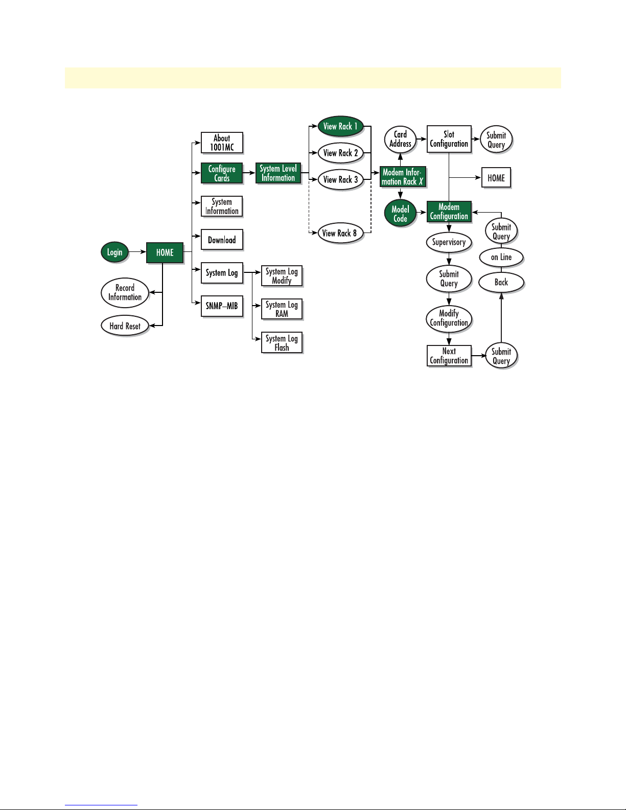
Model 1001MC Operations Guide 6 • Model 1095RC management
Figure 45. Web page navigation to Model 1095 Configuration Slot page
Making configuration changes to your 1095RC NetLink modem
Do use the following to make configuration changes to your NetLink modem.
Note You must be logged in as superuser to perform the following procedure.
1. With the Model 1095 Configuration Slot page displayed, change the Input Mode (see figure 44) to super-
VisoryMode. The Modify Configuration hyperlink will appear.
2. Click on the Modify Configuration hyperlink to display the Model 1095RC Next Configuration page.
3. Make your configuration changes or select the Set Default Configuration button.
4. Select the Submit Query button to place the changes into the 1001MC’s temporary memory. If you decide
that you do not want your changes implemented, you can select the
Clear Changes button.
5. Select the Back hyperlink to return to the Model 1095 Configuration Slot page.
6. Change the Input Mode back to onLine and select the Submit Query button. When the unit returns to the
online state, the 1095RC will begin implementing the configuration changes.
Note The variables that you changed are now highlighted in yellow. After the
1095RC processes the new information, the highlighting will be
removed.
For more information about items on the Model 1095 Configuration Slot page, see “After submitting the
remote circuit ID information, you must click on the Record Current Configuration button located on the
HOME page to store the configuration changes into memory (see “HOME” on page 228 for more information).” on page 104.
Configuration and management 96
Page 97

Model 1001MC Operations Guide 6 • Model 1095RC management
Displaying the Model 1095 Configuration—Next Configuration page
The Model 1095 Configuration—Next Configuration page (see figure 46) enables you to make configuration
changes to the Model 1095RC and the remote CPE box. When the page displays, the unit is set to the onLine
state and the current configuration is displayed.
Figure 46. Model 1095 Configuration—Next Configuration page
Starting from the HOME page, to access the Model 1095 Configuration—Next Configuration page for the
1095RC, click on the following links: Configure Cards > View Rack 1 > Local_Model_Code for the 1095RC you
wish to manage > Modify Configuration (you first have to change input mode from onLine to superVisoryMode.
Figure 47 on page 98 shows the web page navigation required to get to this area of the system.
For more information about items on the Model 1095 Configuration—Next Configuration page, see “Model
1095 Configuration—Next Configuration page MIB variables description” on page 107.
Configuration and management 97
Page 98

Model 1001MC Operations Guide 6 • Model 1095RC management
Figure 47. Web page navigation to Model 1095 Configuration—Next Configuration page
Configuration and management 98
Page 99

Model 1001MC Operations Guide 6 • Model 1095RC management
Displaying the Slot Configuration page
The Slot Configuration page (see figure 48) is used to set slot-specific information related to the system and how
the system treats that slot in the case of errors or warnings.
Figure 48. Slot Configuration page
Starting from the HOME page, to access the Slot Configuration page for the 1095RC, click on the following
links: Configure Cards > View Rack 1 > Card_Address for the 1095RC you wish to manage (in the example
shown in figure 48, the 1095RC was installed in slot 1). Figure 49 on page 100 shows the web page navigation
required to get to this area of the system.
Configuration and management 99
Page 100

Model 1001MC Operations Guide 6 • Model 1095RC management
Figure 49. Web page navigation to Slot Configuration page
For more information about items on the Slot Configuration page, see “Slot Configuration page MIB variables
description” on page 110.
Displaying the Download page
The Download page (see figure 50) is where you can download the latest version of 1001MC and
1095RC software.
Configuration and management 100
Figure 50. Download page
 Loading...