

Page 1
Model 2604
T1/E1 Digital Access and
Cross-Connect System (DACS)
Administrator’s Reference Guide
Sales Office: +1 (301) 975-1000
Technical Support: +1 (301) 975-1007
E-mail: support@patton.com
WWW: www.patton.com
Document Number: 110051UA Rev. A
Part Number: O7MD2604DACS-ARG-A
Revised: February 20, 2002
Page 2

Patton Electronics Company, Inc.
7622 Rickenbacker Drive
Gaithersburg, MD 20879 USA
Voice: +1 (301) 975-1000
Fax: +1 (301) 869-9293
Technical Support: +1 (301) 975-1007
Technical Support e-mail: support@patton.com
WWW: www.patton.com
Copyright © 2001, Patton Electronics Company. All rights reserved.
The information in this document is subject to change without notice. Patton Electronics assumes no liability
for errors that may appear in this document.
The software described in this document is furnished under a license and may be used or copied only in accor-
dance with the terms of such license.
Page 3

Contents
About this guide ...................................................................................................................................................13
Audience............................................................................................................................................................... 13
Structure............................................................................................................................................................... 13
Typographical conventions used in this document................................................................................................ 14
General conventions .......................................................................................................................................14
Mouse conventions .........................................................................................................................................15
1 Introduction ................................................................................................................................................. 17
Introduction..........................................................................................................................................................18
Logging into the HTTP/HTML Administration Pages .........................................................................................18
HTTP/HTML and SNMP Object Format ...........................................................................................................18
Saving HTTP/HTML Object Changes .................................................................................................................19
2 Home............................................................................................................................................................. 21
Introduction..........................................................................................................................................................22
Operating Status Variables ....................................................................................................................................23
% CPU Idle (boxIdleTime) ............................................................................................................................23
Running Since Last Boot (sysUpTime) ...........................................................................................................23
Total System Alarms (alarmTotal) ..................................................................................................................23
Immediate Actions ................................................................................................................................................23
Record Current Configuration (storeConfig(1)) .............................................................................................23
Hard Reset (hardReset(2)) ..............................................................................................................................24
Set Factory Default Configuration (forceDefaultConfig(3)) ............................................................................24
3 Import/Export............................................................................................................................................... 25
Introduction..........................................................................................................................................................26
Export Configuration ............................................................................................................................................26
Import Configuration............................................................................................................................................28
4 Alarms ........................................................................................................................................................... 29
Introduction..........................................................................................................................................................30
Displaying the alarms window...............................................................................................................................30
Alarm Response Outputs ................................................................................................................................32
Relay Response ..........................................................................................................................................32
Minor Alarm SYSLOG Priority (minSyslogPriority) .................................................................................32
Major Alarm SYSLOG Priority (majorSyslogPriority) ...............................................................................32
Minor Alarm SNMP Trap IP [address] (minorTrapIp) .............................................................................32
Major Alarm SNMP Trap IP [address] (majorTrapIp) ..............................................................................32
Temperature Threshold .............................................................................................................................32
Current Box Temperature .........................................................................................................................32
Clear All Alarms ........................................................................................................................................32
Alarms ............................................................................................................................................................32
Alarm ID ...................................................................................................................................................32
1
Page 4

Contents
DSL DACS Administrators’ Reference Guide
Alarm Name .............................................................................................................................................32
Alarm Time ...............................................................................................................................................33
Alarm Count .............................................................................................................................................33
Generate Alarm .........................................................................................................................................33
Clear Alarm ...............................................................................................................................................33
Alarm Parameters ............................................................................................................................................33
Types of Alarms ..............................................................................................................................................34
Modify Response—Configuring the alarm response system...................................................................................34
Relay Response ...............................................................................................................................................34
Minor Alarm Syslog Priority & Major Alarm Syslog Priority ..........................................................................34
Minor Alarm SNMP Trap IP [address] (minSyslogPriority) ...........................................................................34
Major Alarm SNMP Trap IP [address] (majorSyslogPriority) .........................................................................34
Temperature Threshold ..................................................................................................................................35
Modify Alarms—Configuring alarm severity levels ................................................................................................35
5 DS0 Mapping................................................................................................................................................ 37
Introduction..........................................................................................................................................................38
Displaying the DS0 Mapping window...................................................................................................................38
DACS Display Type .......................................................................................................................................38
Help (DACS help information) ......................................................................................................................39
Static Connection ...........................................................................................................................................39
ID .............................................................................................................................................................39
Device Type ..............................................................................................................................................39
Device Number .........................................................................................................................................39
Device Slots ..............................................................................................................................................40
Configuration .................................................................................................................................................40
6 Clocking........................................................................................................................................................ 41
Introduction..........................................................................................................................................................42
Configuring the System Clock Settings..................................................................................................................42
Main Reference (daxClockMainRef) ...............................................................................................................42
Fallback Reference (daxClockFallbackRef) ......................................................................................................43
Clock Status (daxClockFailure) .......................................................................................................................43
7 Ethernet......................................................................................................................................................... 45
Introduction..........................................................................................................................................................46
Ethernet statistics...................................................................................................................................................46
Alignment Errors (dot3StatsAlignmentErrors) ................................................................................................46
FCS Errors (dot3StatsFCSErrors) ...................................................................................................................46
Single Collision Frames (dot3StatsSingleCollision Frames) .............................................................................46
Multiple Collision Frames (dot3StatsMultipleCollisionFrames) ......................................................................47
SQE Test Errors (dot3StatsSQETestErrors) ....................................................................................................47
Deferred Transmissions (dot3StatsDeferredTransmissions) .............................................................................47
Late Collisions (dot3StatsLateCollisions) ........................................................................................................47
Excessive Collisions (dot3StatsExcessiveCollisions) .........................................................................................47
Other Errors (dot3StatsInternalMacTransmitErrors) ......................................................................................47
2
Page 5

3
DSL DACS Administrators’ Reference Guide
Contents
Carrier Sense Errors (dot3StatsCarrierSenseErrors) .........................................................................................47
Received Frames Too Long (dot3StatsFrameTooLongs) .................................................................................47
Other Received Errors (dot3StatsInternalMacReceiveErrors) ..........................................................................48
Chip Set ID (dot3StatsEtherChipSet) .............................................................................................................48
8 Filter IP ......................................................................................................................................................... 49
Introduction..........................................................................................................................................................50
Defining a filter .....................................................................................................................................................50
Name (filterIpName) ......................................................................................................................................52
Direction (filterIpDirection) ...........................................................................................................................52
Action (filterIpAction) ....................................................................................................................................52
Source IP (filterIpSourceIp) ............................................................................................................................52
Source IP Mask (filterIpSourceMask) ..............................................................................................................52
Destination IP (filterIpDestinationIp) .............................................................................................................52
Destination Mask (filterIpDestinationMask) ...................................................................................................53
Source Port (FilterIpSourcePort) .....................................................................................................................53
Action (filterIpSourcePortCmp) ......................................................................................................................53
Destination Port (filterIpDestinationPort) ......................................................................................................53
Action (filterIpDestinationPortCmp) ..............................................................................................................53
Protocol (filterIpProtocol) ...............................................................................................................................53
TCP Established (filterIpTcpEstablished) .......................................................................................................53
9 ICMP ............................................................................................................................................................ 55
Introduction..........................................................................................................................................................56
Block ICMP redirects (boxBLockIcmpRedirects) ..................................................................................................56
ICMP Receive/Send Messages window..................................................................................................................56
Total Received (icmpInMsgs) .........................................................................................................................56
Total Sent [imcpOutMsgs] .............................................................................................................................57
w/Errors (icmpInErrors, icmpOutErrors) ........................................................................................................57
wo/Errors [icmpOutErrors] ............................................................................................................................57
Destinations Unreachable (IcmpInDestUnreachs, IcmpOutDestUnreachs) ....................................................57
Times Exceeded (icmpInTimeExcds, icmpOutTimeExcds) ............................................................................57
Parameter Problems (icmpInParmProbs, icmpOutParmProbs) .......................................................................57
Source Quenchs (icmpInSrcQuenchs, icmpOutSrcQuenchs) .........................................................................57
Redirects (icmpInRedirects, icmpOutRedirects) .............................................................................................58
Echos (icmpInEchos, icmpOutEchos) .............................................................................................................58
Echo Replys (icmpInReps, icmpOutReps) ......................................................................................................58
Time Stamps (icmpInTimestamps, icmpInTimestamps) .................................................................................58
Time Stamp Replys (icmpInTimestampsReps) (icmpOutTimestampsReps) ...................................................58
Address Mask Requests (icmpInAddrMasks) (icmpOutAddrMasks) ...............................................................58
Address Mask Replys (icmpInAddrMasksReps) (icmpOutAddrMasksReps) ....................................................58
10 IP................................................................................................................................................................... 59
Introduction..........................................................................................................................................................61
IP main window ....................................................................................................................................................61
Forwarding (ipForwarding) .............................................................................................................................62
Page 6

Contents
DSL DACS Administrators’ Reference Guide
Default Time-To-Live (ipDefaultTTL) ...........................................................................................................62
Total Datagrams Received (ipInReceives) .......................................................................................................62
Discarded for Header Errors (ipInHdrErrors) .................................................................................................62
Discarded for Address Errors (ipInAddrErrors) ...............................................................................................62
Forwarded Datagrams (ipForwDatagrams) .....................................................................................................62
Discarded for Unknown Protos (ipInUnknownProtos) ...................................................................................62
Discarded w/No Errors (ipInDiscards) ............................................................................................................62
Total Deliveries (ipInDelivers) ........................................................................................................................63
Out Requests (ipOutRequests) ........................................................................................................................63
Out Discards (ipOutDiscards) ........................................................................................................................63
Discarded for No Routes (ipOutNoRoutes) ....................................................................................................63
Reassembly Timeout (ipReasmTimeout) ........................................................................................................63
# of Reassembled Fragments (ipReasmReqds) .................................................................................................63
# Successfully Reassembled (ipReasmOKs) .....................................................................................................63
Reassembly Failures (ipReasmFails) .................................................................................................................63
# Fragmented OK (ipFragOKs) ......................................................................................................................64
# Fragmented Failed (ipFragFails) ...................................................................................................................64
# Fragments Created (ipFragCreates) ..............................................................................................................64
# Valid but Discarded (ipRoutingDiscards) ....................................................................................................64
Modify ..................................................................................................................................................................64
Forwarding (ipForwarding) .............................................................................................................................64
Default Time-To-Live (ipDefaultTTL) ...........................................................................................................64
Addressing Information.........................................................................................................................................65
IP addressing Information Details ...................................................................................................................65
Entry Interface Index (ipAdEntIfIndex) ....................................................................................................65
Entry Subnet Mask (ipAdEntNetMask) ....................................................................................................65
Entry Broadcast Address (ipAdEntBcastAddr) ...........................................................................................65
Entry Reassembly Maximum Size (ipAdEntReasmMaxSize) .....................................................................65
Routing Information .............................................................................................................................................66
Destination (ipRouteDest) ..............................................................................................................................66
Mask (ipRouteMask) ......................................................................................................................................67
Gateway (RouteGateway) ................................................................................................................................67
Cost (RouteCost) ............................................................................................................................................67
Interface (ipRouteIfIndex) ..............................................................................................................................67
State (RouteState) ...........................................................................................................................................67
Add a route: ....................................................................................................................................................67
Advanced… ....................................................................................................................................................67
O/S forwarding table window................................................................................................................................68
Destination (ipRouteDest) ..............................................................................................................................68
Mask (ipRouteMask) ......................................................................................................................................68
Next Hop (ipRouteNextHop) .........................................................................................................................68
Interface (ipRouteIfIndex) ..............................................................................................................................68
Type (ipRouteType) .......................................................................................................................................68
Protocol (ipRouteProto) ..................................................................................................................................69
4
Page 7

5
DSL DACS Administrators’ Reference Guide
Contents
Info (ipRouteInfo) ..........................................................................................................................................69
IP Routing Destination window............................................................................................................................70
Route Destination (ipRouteDest) ...................................................................................................................70
Mask (ipRouteMask) ......................................................................................................................................70
Interface (ipRouteIfIndex) ..............................................................................................................................70
Protocol (ipRouteProto) ..................................................................................................................................70
Seconds Since Updated (ipRouteAge) .............................................................................................................71
Tag (RouteTag) ..............................................................................................................................................71
Gateway (RouteGateway) ................................................................................................................................71
Cost (RouteCost) ............................................................................................................................................71
State (RouteState) ...........................................................................................................................................71
Address Translation Information ...........................................................................................................................71
Interface (ipNetToMediaEntry) ......................................................................................................................71
Net Address (ipNetToMediaNetAddress) .......................................................................................................72
Physical (ipNetToMediaPhysAddress) ............................................................................................................72
Type (ipNetToMediaType) ............................................................................................................................72
11 TCP............................................................................................................................................................... 73
Introduction..........................................................................................................................................................74
TCP main window ................................................................................................................................................74
Retransmit-Timeout Algorithm (tcpRtoAlgorithm) ........................................................................................74
Retransmit-Timeout Minimum (tcpRtoMin) .................................................................................................74
Retransmit-Timeout Maximum (tcpRtoMax) .................................................................................................74
Maximum Connections (tcpMaxConn) ..........................................................................................................75
Active Opens (tcpActiveOpens) ......................................................................................................................75
Passive Opens (tcpPassiveOpens) ....................................................................................................................75
Attempt/Fails (tcpAttemptFails) ......................................................................................................................75
ESTABLISHED Resets (tcpEstabResets) ........................................................................................................75
Current ESTABLISHED (tcpCurrEstab) .......................................................................................................75
Total Received (tcpInSegs) ..............................................................................................................................75
Total Sent (tcpOutSegs) ..................................................................................................................................75
Total Retransmitted (tcpRetransSegs) .............................................................................................................75
Total Received in Error (tcpInErrs) .................................................................................................................75
Total Sent w/RST Flag (tcpOutRsts) ..............................................................................................................75
TCP (Details)........................................................................................................................................................76
Local Port (tcpConnLocalPort) .......................................................................................................................76
Remote Address (tcpConnRemAddress) .........................................................................................................76
Remote Port (tcpConnRemPort) ....................................................................................................................76
State (tcpConnState) .......................................................................................................................................76
12 UDP .............................................................................................................................................................. 79
Introduction..........................................................................................................................................................80
Handling of NETBIOS UDP Broadcasts (boxNetbiosUdpBridging) ..............................................................80
Received (udpInDatagrams) ............................................................................................................................80
Received With No Ports (udpNoPorts) ...........................................................................................................80
Page 8

Contents
DSL DACS Administrators’ Reference Guide
Others Received with No Delivery (udpInErrors) ...........................................................................................80
Sent (udpOutDatagrams) ................................................................................................................................80
Listener Table (udpTable) ...............................................................................................................................81
Local Address (udpLocalAddress) ....................................................................................................................81
Local Port (udpLocalPort) ...............................................................................................................................81
13 RIP Version 2................................................................................................................................................ 83
Introduction..........................................................................................................................................................84
RIP Version 2 main window..................................................................................................................................84
Route Changes Made (rip2GlobalRouteChanges) ...........................................................................................84
Responses Sent (rip2GlobalQueries) ...............................................................................................................84
Adding a RIP address ......................................................................................................................................84
RIP Version 2—Configuration..............................................................................................................................85
Address (rip2IfConfAddress) ...........................................................................................................................85
Domain (rip2IfConfDomain) .........................................................................................................................86
Authentication Type (rip2IfConfAuthType) ...................................................................................................86
Authentication Key (rip2IfConfAuthKey) .......................................................................................................86
Send (rip2IfConfSend) ....................................................................................................................................86
Receive (rip2IfConfReceive) ...........................................................................................................................86
Metric (rip2IfConfDefaultMetric) ..................................................................................................................86
Status (rip2IfConfStatus) ................................................................................................................................87
RIP Version 2 (Statistics).......................................................................................................................................87
Subnet IP Address (rip2IfStatAddress) ............................................................................................................87
Bad Packets (rip2IfStatRcvBadPackets) ...........................................................................................................87
Bad Routes (rip2IfStatRcvBadRoutes) ............................................................................................................87
Sent Updates (rip2IfStatSentUpdates) .............................................................................................................87
Status (rip2IfStatStatus) ..................................................................................................................................87
14 SNMP............................................................................................................................................................ 89
Introduction..........................................................................................................................................................90
SNMP window......................................................................................................................................................90
In ..........................................................................................................................................................................90
Packets (snmpInPkts) ......................................................................................................................................90
Bad Version (snmpInBadVersions) .................................................................................................................90
Bad Community Names (snmpInBadCommunityNames) ..............................................................................91
Bad Community Uses (snmpInBadCommunity) ............................................................................................91
ASN ParseErrors (snmpInASNParseErrs) ........................................................................................................91
Error Status “Too Big” (snmpInTooBigs) .......................................................................................................91
No Such Names (snmpInNoSuchNames) .......................................................................................................91
Bad Values (snmpInBadValues) ......................................................................................................................91
Error Status “Read Only” (snmpInReadOnlys) ...............................................................................................91
Generated Errors (snmpInGenErrs) ................................................................................................................91
Get/Get Next Variables (snmpInTotalReqVars) .............................................................................................91
Set Variables (snmpInTotalSetVars) ................................................................................................................91
Get Requests (snmpInGetRequests) ................................................................................................................91
6
Page 9

7
DSL DACS Administrators’ Reference Guide
Contents
Get Next Requests (snmpInGetNexts) ............................................................................................................92
Set Requests (snmpInSetRequests) ..................................................................................................................92
Get Responses (snmpInGetResponses) ............................................................................................................92
Traps (snmpInTraps) ......................................................................................................................................92
Out .......................................................................................................................................................................92
Out Packets (snmpOutPkts) ...........................................................................................................................92
Error Status “Too Big” (snmpOutTooBigs) ....................................................................................................92
No Such Names (snmpOutNoSuchNames) ....................................................................................................92
Bad Values (snmpOutBadValues) ...................................................................................................................92
Generated Errors (snmpOutGenErrs) .............................................................................................................92
Get Requests (snmpOutGetRequests) .............................................................................................................92
Get Next Requests (snmpOutGetNexts) .........................................................................................................92
Set Requests (snmpOutSetRequests) ...............................................................................................................92
Get Responses (snmpOutGetResponses) .........................................................................................................93
Traps (snmpOutTraps) ...................................................................................................................................93
Authentication Failure Traps (snmpEnableAuthenTraps) ...............................................................................93
15 System ........................................................................................................................................................... 95
Introduction..........................................................................................................................................................97
System main window.............................................................................................................................................98
CPU ...............................................................................................................................................................98
Percentage CPU Idle (boxidletime) ...........................................................................................................98
Time Slices Fully Utilized (boxCPUcritical) ..............................................................................................98
Time Slices 90% Utilized (boxCPUWarning) ...........................................................................................98
SNMP and HTTP ..........................................................................................................................................98
Version (boxSnmpVersion) .......................................................................................................................98
Super User Password (boxSnmpMasterPassword) ......................................................................................98
User Password (boxSnmpMonitorPassword) .............................................................................................98
LAN IP ...........................................................................................................................................................98
How to Obtain Address (boxIPAddressTechnique) ...................................................................................99
Address(boxIPAddress) ..............................................................................................................................99
Mask(boxIPMask) .....................................................................................................................................99
Manufacturer ..................................................................................................................................................99
Serial Number (boxManufactureDatecode) ...............................................................................................99
PCB Revision (boxManufacturePcbRevision) ............................................................................................99
General Information (boxManufactureGeneralInfo) .................................................................................99
Message Blocks ...............................................................................................................................................99
Packet Holding Message Blocks... .............................................................................................................99
Total (boxMsgBlksConfigured) .................................................................................................................99
Free (boxMsgBlksFree) ..............................................................................................................................99
Total Time Waited (boxCountMsgBlkTaskWait) .....................................................................................99
Total Times Unavailable (boxCountMsgBlkUnavailable) ........................................................................100
Operating System Heap Memory ..................................................................................................................100
Total Size (boxHeapSize) ........................................................................................................................100
Page 10

Contents
DSL DACS Administrators’ Reference Guide
Free (boxHeapFreeSpace) ........................................................................................................................100
Largest (boxHeapLargestSpace) ...............................................................................................................100
Enclosure System ..........................................................................................................................................100
Internal Temperature (boxTemperature) .................................................................................................100
Highest Temperature (boxMaxTemperature) ..........................................................................................100
Installation ....................................................................................................................................................100
Country (installCountry) ........................................................................................................................100
Other ............................................................................................................................................................100
Total DRAM Detected (boxDetectedMemory) .......................................................................................100
SystemID (sysObjectID) .........................................................................................................................100
Running Since Last Boot (sysUpTime) ...................................................................................................101
System Manager (sysContact) ..................................................................................................................101
Box Name (sysName) ..............................................................................................................................101
Physical Location (sysLocation) ...............................................................................................................101
Web Settings (boxBackgroundFlag) ........................................................................................................101
Monitor Privilege (boxMonitorPrivilege) ................................................................................................101
System—Modify window....................................................................................................................................102
SNMP and HTTP ........................................................................................................................................102
Version (boxSnmpVersion) .....................................................................................................................102
Super User Password (boxSnmpMasterPassword) ....................................................................................102
User Password (boxSnmpMonitorPassword) ...........................................................................................103
LAN IP .........................................................................................................................................................103
Method to Obtain Address (boxIPAddressTechnique) ............................................................................103
Address (boxIPAddress) ...........................................................................................................................103
Mask (boxIPMask) ..................................................................................................................................103
Installation ....................................................................................................................................................103
Country (installCountry) ........................................................................................................................103
Other ............................................................................................................................................................104
System Manager (sysContact) ..................................................................................................................104
Box Name (sysName) ..............................................................................................................................104
Physical Location (sysLocation) ...............................................................................................................104
Web Settings (boxBackgroundFlag) ........................................................................................................104
Monitor Privilege (boxMonitorPrivilege) ................................................................................................104
System—Packet Holding Message Blocks............................................................................................................105
Buffer Size (boxbuffersize) .............................................................................................................................105
No. of Buffers (boxbuffercount) ....................................................................................................................105
No. Free (boxbuffersfree) ..............................................................................................................................105
No. of Tasks Waited (boxCountBufferTaskWait) .........................................................................................105
No. of Times Unavailable(boxCountBufferUnavailable) ...............................................................................105
16 System Log .................................................................................................................................................. 107
Introduction........................................................................................................................................................108
System Log Main Window ..................................................................................................................................108
System Log—Modify ..........................................................................................................................................109
8
Page 11

9
DSL DACS Administrators’ Reference Guide
Daemons ......................................................................................................................................................109
SysLog Daemon IP Address(syslogDaemonIP) ........................................................................................109
SNMP Trap Daemon IP Address (syslogTrapIP) ....................................................................................109
Priority .........................................................................................................................................................109
Min Priority for SysLog Daemon (syslogDaemonPriority) ......................................................................110
Min Priority for Console RS-232 (syslogConsolePriority) .......................................................................110
Min Priority for Flash Storage (syslogFlashPriority) ................................................................................110
Min Priority for SNMP Trap Daemon (syslogTrapPriority) ...................................................................110
Min Priority for RAM (SyslogTablePriority) ...........................................................................................111
Unix Facility (syslogUnixFacility) ...........................................................................................................111
Call Trace (syslogCallTrace) ....................................................................................................................112
Maintenance .................................................................................................................................................112
Maintain Flash Storage (syslogFlashClear) ...............................................................................................112
System Log—Volatile Memory............................................................................................................................113
Time (slTick) ................................................................................................................................................113
Message (slMessage) ......................................................................................................................................113
System Log—Non-Volatile Memory ...................................................................................................................114
Time (slfTick) ...............................................................................................................................................114
Message (slfMessage) .....................................................................................................................................114
Contents
17 T1/E1 Link.................................................................................................................................................. 115
Introduction........................................................................................................................................................118
T1/E1 Link Activity main window......................................................................................................................119
Link (dsx1LineIndex) ....................................................................................................................................119
Type (dsx1LineType) ....................................................................................................................................119
Circuit ID (dsx1CircuitIdentifier) .................................................................................................................119
Line Status (dsx1LineStatus)................................................................................................................................120
Failure States .................................................................................................................................................120
Far End Alarm Failure .............................................................................................................................120
Alarm Indication Signal (AIS) Failure .....................................................................................................121
Loss Of Frame Failure .............................................................................................................................121
Loss Of Signal Failure .............................................................................................................................121
Loopback Pseudo-Failure ........................................................................................................................121
TS16 Alarm Indication Signal Failure .....................................................................................................121
Loss Of MultiFrame Failure ....................................................................................................................121
Far End Loss Of Multiframe Failure .......................................................................................................121
Line Status—Configuration.................................................................................................................................122
Time Elapsed (dsx1TimeElapsed) .................................................................................................................122
Valid Intervals (dsx1ValidIntervals) ...............................................................................................................122
WAN Circuit Configuration—Modify................................................................................................................123
Line Interface Settings ...................................................................................................................................123
Circuit ID (dsx1CircuitIdentifier) ...........................................................................................................123
Line Type (dsx1LineType) Type (dsx1LineType) ....................................................................................123
Line Coding (dsx1LineCoding) ...............................................................................................................124
Page 12

Contents
DSL DACS Administrators’ Reference Guide
Receive Equalizer (linkRxEqualizer) ........................................................................................................124
Line Build Out (linkLineBuildOut) ........................................................................................................124
Yellow Alarm Format (linkYellowFormat) ...............................................................................................124
FDL (dsx1FDL) ......................................................................................................................................125
Test Settings .................................................................................................................................................125
Force Yellow Alarm (linkYellowForce) ....................................................................................................125
Loopback Config (dsx1LoopbackConfig) ................................................................................................125
Send Code (dsx1SendCode) ....................................................................................................................125
Error Injection (linkInjectError) ..............................................................................................................126
Yellow Alarm Severity () ..........................................................................................................................126
Red Alarm Severity () .............................................................................................................................126
Near End Line Statistics—Current......................................................................................................................127
Errored Seconds (dsx1CurrentESs) ...............................................................................................................127
Severely Errored Seconds (dsx1CurrentSESs) ................................................................................................127
Severely Errored Frame Seconds (dsx1CurrentSEFSs) ...................................................................................127
Unavailable Seconds (dsx1CurrentUASs) ......................................................................................................127
Controlled Slip Seconds (dsx1CurrentCSSs) .................................................................................................127
Path Code Violations (dsx1CurrentPCVs) ....................................................................................................127
Line Errored Seconds (dsx1CurrentLESs) .....................................................................................................127
Bursty ErroredSeconds (dsx1CurrentBESs) ...................................................................................................127
Degraded Minutes (dsx1CurrentDMs) .........................................................................................................128
Line Code Violations (dsx1CurrentLCVs) ....................................................................................................128
Near End Line Statistics—History.......................................................................................................................128
Interval (dsx1IntervalNumber) ......................................................................................................................128
Errored Seconds (dsx1intervaless) ..................................................................................................................128
Severely Errored Seconds (dsx1IntervalSESs) ................................................................................................128
Severely Errored Frame Seconds (dsx1IntervalSEFSs) ...................................................................................129
Unavailable Seconds (dsx1IntervalUASs) ......................................................................................................129
Controlled Slip Seconds (dsx1IntervalCSSs) .................................................................................................129
Path Code Violations (dsx1IntervalPCVs) ....................................................................................................129
Line Errored Seconds (dsx1IntervalLESs) ......................................................................................................129
Bursty ErroredSeconds (dsx1IntervalBESs) ...................................................................................................129
Degraded Minutes (dsx1IntervalDMs) ..........................................................................................................129
Line Code Violations (dsx1IntervalLCVs) .....................................................................................................129
Near End Line Statistics—Totals.........................................................................................................................130
Errored Seconds (dsx1TotalESs) ...................................................................................................................130
Severely Errored Seconds (dsx1TotalSESs) ....................................................................................................130
Severely Errored Frame Seconds (dsx1TotalSEFSs) .......................................................................................130
Unavailable Seconds (dsx1TotalUASs) ..........................................................................................................130
Controlled Slip Seconds (dsx1TotalCSSs) .....................................................................................................130
Path Code Violations (dsx1TotalPCVs) ........................................................................................................130
Line Errored Seconds (dsx1TotalLESs) .........................................................................................................130
Bursty ErroredSeconds (dsx1TotalBESs) .......................................................................................................130
Degraded Minutes (dsx1TotalDMs) .............................................................................................................131
10
Page 13

11
DSL DACS Administrators’ Reference Guide
Line Code Violations (dsx1TotalLCVs) ........................................................................................................131
Far End Line Statistics—Current.........................................................................................................................131
Time Elapsed (dsx1FarEndTimeElapsed) ......................................................................................................131
Errored Seconds (dsx1FarEndCurrentESs) ....................................................................................................131
Severely Errored Seconds (dsx1FarEnd CurrentSESs) ...................................................................................131
Severely Errored Frame Seconds (dsx1FarEndCurrentSEFSs) .......................................................................131
Unavailable Seconds (dsx1FarEndCurrentUASs) ..........................................................................................131
Controlled Slip Seconds (dsx1FarEndCurrentCSSs) .....................................................................................132
Line Errored Seconds (dsx1FarEndCurrentLESs) ..........................................................................................132
Path Code Violations (dsx1FarEndCurrentPCVs) ........................................................................................132
Bursty Errored Seconds (dsx1FarEndCurrentBESs) ......................................................................................132
Degraded Minutes (dsx1FarEndCurrentDMs) ..............................................................................................132
Far End Line Statistics—History .........................................................................................................................132
Interval (dsx1FarEndIntervalNumber) ..........................................................................................................133
Errored Seconds (dsx1FarEndIntervalESs) ....................................................................................................133
Severely Errored Seconds (dsx1FarEndIntervalSESs) .....................................................................................133
Severely Errored Frame Seconds (dsx1FarEndIntervalSEFSs) ........................................................................133
Unavailable Seconds (dsx1FarEndIntervalUASs) ...........................................................................................133
Controlled Slip Seconds (dsx1FarEndIntervalCSSs) ......................................................................................133
Line Errored Seconds (dsx1FarEndIntervalLESs) ..........................................................................................133
Path Code Violations (dsx1FarEndIntervalPCVs) .........................................................................................133
Bursty Errored Seconds (dsx1FarEndIntervalBESs) .......................................................................................133
Degraded Minutes (dsx1FarEndIntervalDMs) ..............................................................................................133
Far End Line Statistics—Totals ...........................................................................................................................134
Errored Seconds (dsx1FarEndTotalESs) ........................................................................................................134
Severly Errored Seconds (dsx1FarEndTotalSESs) ..........................................................................................134
Severely Errored Frame Seconds (dsx1FarEndTotalSEFSs) ...........................................................................134
Unavailable Seconds (dsx1FarEndTotalUASs) ..............................................................................................134
Controlled Slip Seconds (dsx1FarEndTotalCSSs) .........................................................................................134
Line Errored Seconds (dsx1FarEndTotalLESs) ..............................................................................................134
Path Code Violations (dsx1FarEndTotalPCVs) ............................................................................................134
Bursty Errored Seconds (dsx1FarEndTotalBESs) ..........................................................................................135
Degraded Minutes (dsx1FarEndTotalDMs) ..................................................................................................135
Contents
18 T1/E1 Assignment....................................................................................................................................... 137
Introduction........................................................................................................................................................138
Displaying the T1/E1 Assignment window..........................................................................................................138
Slot ...............................................................................................................................................................139
Device ...........................................................................................................................................................139
Port # ............................................................................................................................................................139
Slot # ............................................................................................................................................................139
19 About........................................................................................................................................................... 141
Introduction........................................................................................................................................................142
Patton Electronics Company contact information ...............................................................................................142
Page 14

Contents
DSL DACS Administrators’ Reference Guide
20 License......................................................................................................................................................... 143
Introduction........................................................................................................................................................144
End User License Agreement ...............................................................................................................................144
1. Definitions: ...............................................................................................................................................144
2. Title: .........................................................................................................................................................145
3. Term: ........................................................................................................................................................145
4. Grant of License: .......................................................................................................................................145
5. Warranty: .................................................................................................................................................145
6. Termination: .............................................................................................................................................145
12
Page 15

About this guide
This guide describes configuring a Patton Electronics digital cross connect (DACS). This section describes the
following:
• Who should use this guide (see “Audience”)
• How this document is organized (see “Structure”)
• Typographical conventions and terms used in this guide (see “Typographical conventions used in this docu-
ment” on page 14)
Audience
This guide is intended for the following users:
• System administrators
• Operators
• Installers
• Maintenance technicians
Structure
This guide contains the following chapters:
• Chapter 1 describes configuring the Administration Page window
• Chapter 2 describes configuring the Home window
• Chapter 3 describes configuring the Import/Export window
• Chapter 4 describes configuring the Alarms window
• Chapter 5 describes configuring the DS0 Mapping window
• Chapter 6 describes configuring the Clocking window
• Chapter 7 describes configuring the Ethernet window
• Chapter 8 describes configuring the Filter IP window
• Chapter 9 describes configuring the ICMP window
• Chapter 10 describes configuring the IP window
• Chapter 11 describes configuring the TCP window
• Chapter 12 describes configuring the UDP window
• Chapter 13 describes configuring the RIP Version 2 window
• Chapter 14 describes configuring the SNMP window
• Chapter 15 describes configuring the System window
• Chapter 16 describes configuring the System Log window
13
Page 16

About this guide
T1/E1 DACS Administrators’ Reference Guide
• Chapter 17 describes configuring the T1/E1Link window
• Chapter 18 describes configuring the T1/E1 Assignment window
• Chapter 19 describes the contents of the About window
• Chapter 20 describes the contents of the License window
• Appendix A contains a table with the color code for the RJ-21X connector
Typographical conventions used in this document
This section describes the typographical conventions and terms used in this guide.
General conventions
The procedures described in this manual use the following text conventions:
Table 1. Text conventions
Convention Meaning
Futura bold type
Italicized Futura type
Futura type
Garamond bold type Indicates the names of command buttons that execute an action.
< >
Are you ready? All system messages and prompts appear in the Courier font as the
% dir *.*
Indicates the names of menu bar options.
Indicates the names of options on pull-down menus.
Indicates the names of fields or windows.
Angle brackets indicate function and keyboard keys, such as <SHIFT>,
<CTRL>, <C>, and so on.
system would display them.
Bold Courier font indicates where the operator must type a response or
command
14
Page 17

15
T1/E1 DACS Administrators’ Reference Guide
Mouse conventions
The following conventions are used when describing mouse actions:
Table 2. Mouse conventions
Convention Meaning
Left mouse button
Right mouse button This button refers the secondary or rightmost mouse button (unless you have
Point This word means to move the mouse in such a way that the tip of the pointing
Click Means to quickly press and release the left or right mouse button (as instructed in
Drag This word means to point the arrow and then hold down the left or right mouse
This button refers to the primary or leftmost mouse button (unless you have
changed the default configuration).
changed the default configuration)
arrow on the screen ends up resting at the desired location.
the procedure). Make sure you do not move the mouse pointer while clicking a
mouse button. Double-click means to press and release the same mouse button two
times quickly
button (as instructed in the procedure) as you move the mouse to a new location.
When you have moved the mouse pointer to the desired location, you can release
the mouse button.
About this guide
Page 18

About this guide
T1/E1 DACS Administrators’ Reference Guide
16
Page 19

Chapter 1
Chapter contents
Introduction..........................................................................................................................................................18
Logging into the HTTP/HTML Administration Pages .........................................................................................18
HTTP/HTML and SNMP Object Format ...........................................................................................................18
Saving HTTP/HTML Object Changes .................................................................................................................19
Introduction
17
Page 20
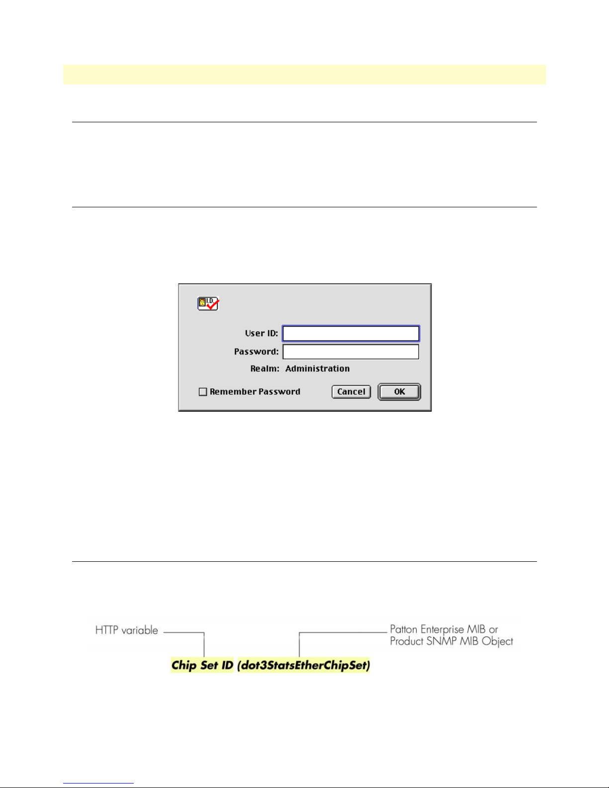
18
1 • Introduction
T1/E1 DACS Administrators’ Reference Guide
Introduction
You may configure the digital cross connect (DACS) by using its internal HTTP/HTML Administration
Pages. However, to enter into the HTTP/HTML pages, you must first define the LAN Address Technique,
LAN IP Address, and LAN Subnet Mask for the DACS. If you have not done so, please refer to the Getting
Started Guide that came with your DACS.
Logging into the HTTP/HTML Administration Pages
To log into the HTTP/HTML Administration pages, you must enter the 4-octet Internet Protocol (IP) (for
example, http://your.server.ip.address ) address as the Universal Resource Locator (URL) into a World-Wide Web
(WWW) browser. After you enter the IP address, the DACS will ask for your user name and password as
shown in figure 1.
Figure 1. DACS login window
Your DACS will accept the following default administrative passwords:
• superuser—this password carries full permission to change and view any parameters in the DACS
• monitor—this password allows full viewing of any non-password oriented variables.
Note For security reasons, we recommend that you change these passwords
immediately after initial configuration.
HTTP/HTML and SNMP Object Format
In this document, we shall describe the variables found on each of the internal HTTP/HTML pages. This
description will include brief definitions of the Patton Enterprise MIB or SNMP MIB II object identifiers
wherever applicable. The format of the variables will resemble figure 2.
Figure 2. HTTP/HTML and SNMP object format
Introduction
Page 21

T1/E1 DACS Administrators’ Reference Guide 1 • Introduction
Saving HTTP/HTML Object Changes
Sometimes you will need to save changes that you have made in the HTTP/HTML pages. Do the following to
make changes to read/write variables:
1. Select the appropriate
Modify screen.
2. Make changes to the desired parameter.
3. Click on the
4. Return to the
5. Click on the
Submit Query button.
HOME screen.
Record Current Configuration button.
Note Make sure you follow steps 1 through 5 when modifying the HTTP/
HTML pages. Otherwise, your changes will be lost when the DACS
is power-cycled.
Saving HTTP/HTML Object Changes 19
Page 22

1 • Introduction T1/E1 DACS Administrators’ Reference Guide
20 Saving HTTP/HTML Object Changes
Page 23

Chapter 2 Home
Chapter contents
Introduction..........................................................................................................................................................22
Operating Status Variables ....................................................................................................................................23
% CPU Idle (boxIdleTime) ............................................................................................................................23
Running Since Last Boot (sysUpTime) ...........................................................................................................23
Total System Alarms (alarmTotal) ..................................................................................................................23
Immediate Actions ................................................................................................................................................23
Record Current Configuration (storeConfig(1)) .............................................................................................23
Hard Reset (hardReset(2)) ..............................................................................................................................24
Set Factory Default Configuration (forceDefaultConfig(3)) ............................................................................24
21
Page 24
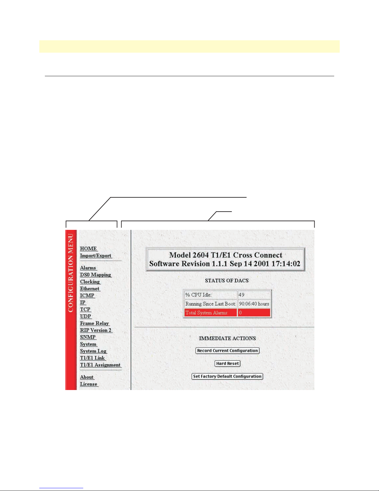
2 • Home T1/E1 DACS Administrators’ Reference Guide
Introduction
This chapter describes the HOME window—the first Administration Page that you see after logging into the
DACS (see figure 3). From
changes, or reset the system without power-cycling the DACS.
Note Clicking on the HOME link in the Configuration Menu pane will
The
HOME window is divided into two panes: the Configuration Menu pane on the left-hand side and the con-
figuration/information pane (see figure 3). The
subsystems, while the configuration/information pane is where you can view status and other information, or
make changes to the system configuration. Unlike the Configuration Menu pane, which looks the same no
matter which subsystem page you are viewing, the configuration/information pane contents will change as you
move from one subsystem page to another.
HOME, you can monitor current systems status, save any system configuration
return you to the
HOME page from any other page.
Configuration Menu contains the links to the various DACS
Configuration Menu pane
Configuration/information pane
22 Introduction
Figure 3. HOME page
Page 25
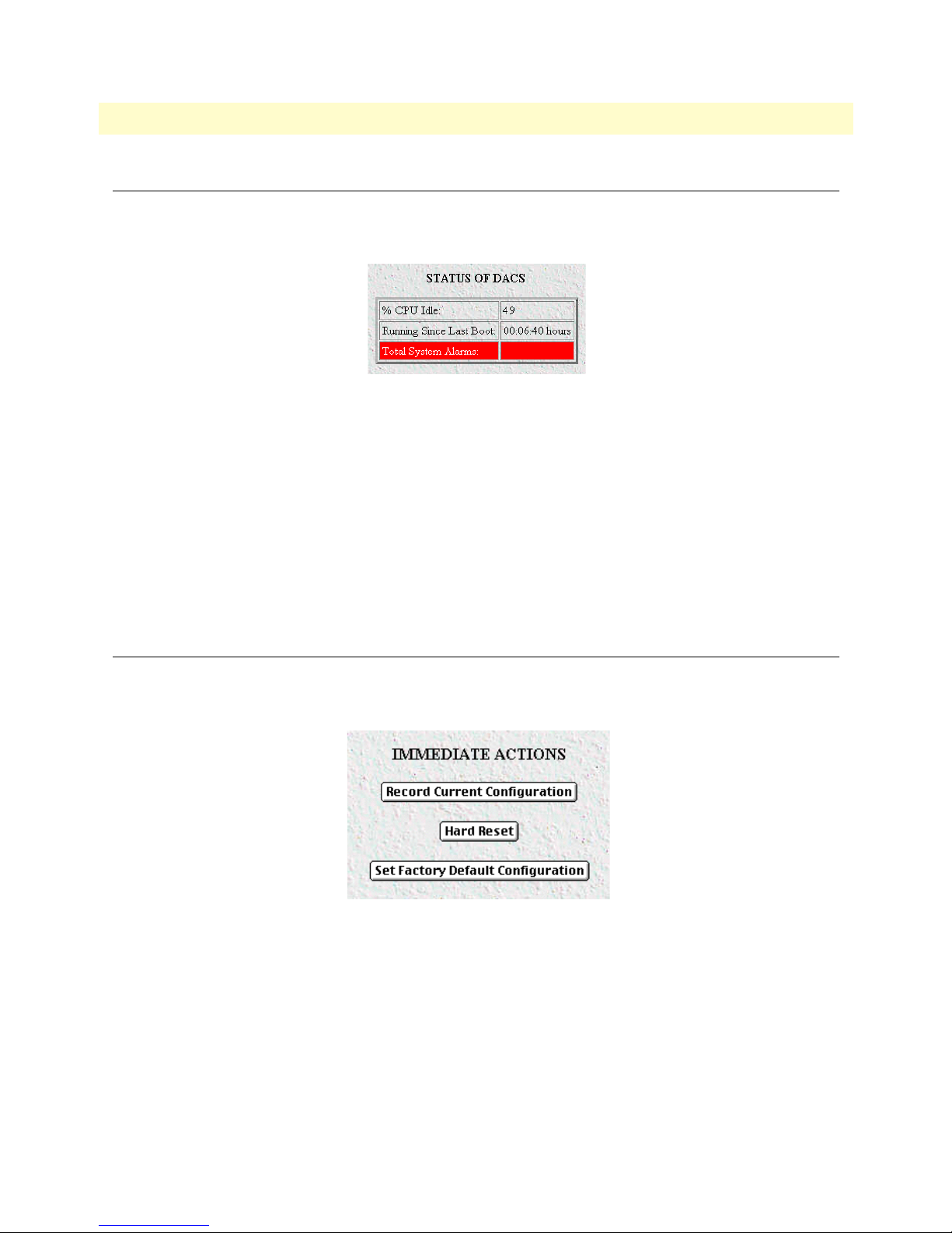
T1/E1 DACS Administrators’ Reference Guide 2 • Home
Operating Status Variables
There are seven system variables which describe the immediate operating status of the DACS. These variables
are shown in figure 4 and are described in the following sections.
Figure 4. STATUS menu
% CPU Idle (boxIdleTime)
This is an indication of the amount of system CPU power which is not being utilized by the Model 2604. The
return value is a percentage of free CPU cycles since the last time the variable was read.
Running Since Last Boot (sysUpTime)
The time (in hundredths of a second) since the DACS was last power-cycled.
Total System Alarms (alarmTotal)
Total number of alarms currently active in the system.
Immediate Actions
There are several immediate actions (see figure 5) in superuser mode which will cause the DACS to operate
according to the descriptions in the following sections.
Figure 5. Immediate Actions buttons
Record Current Configuration (storeConfig(1))
This feature saves the current configuration in permanent FLASH memory. In other words, configuration
changes made in the subsystem web pages become permanent when you select Record Current Configuration.
1. Configuration changes in the DACS are made in the subsystem web pages by clicking Submit Query.
This stores the configuration in volatile DRAM (Dynamic RAM) only. Since the Submit Query changes
take immediate effect, the administrator can test different configuration parameters without needing to
change the FLASH configuration at this moment.
Operating Status Variables 23
Page 26

2 • Home T1/E1 DACS Administrators’ Reference Guide
2. Without clicking on Record Current Configuration, all configuration changes will be lost if the power
is recycled. After doing the Record Current Configuration save, the current configuration of the DACS
will not be lost with power cycling.
Note The most important step after completing the configuration is to save it in
permanent memory by clicking on Record Current Configuration.
Hard Reset (hardReset(2))
This button causes the DACS to perform a cold restart. When you select Hard Reset, the DACS requests confirmation for the execution of this command. Then, the DACS will disconnect all current sessions, re-initialize
the interfaces, and re-load configuration parameters from FLASH.
Set Factory Default Configuration (forceDefaultConfig(3))
This button clears out the configuration in FLASH and loads the factory default parameters into FLASH
memory. The factory default settings will not execute on the DACS until it is re-booted, for example by doing
a Hard Reset.
Note Set Factory Default Configuration will delete the DACS’s Ether-
net IP address and any other site specific settings made for your particular installation. You will have to re-enter the DACS’s Ethernet IP
address and netmask using the front panel control port in order to use
the HTTP/HTML Management pages.
24 Immediate Actions
Page 27

Chapter 3 Import/Export
Chapter contents
Introduction..........................................................................................................................................................26
Export Configuration ............................................................................................................................................26
Import Configuration............................................................................................................................................28
25
Page 28
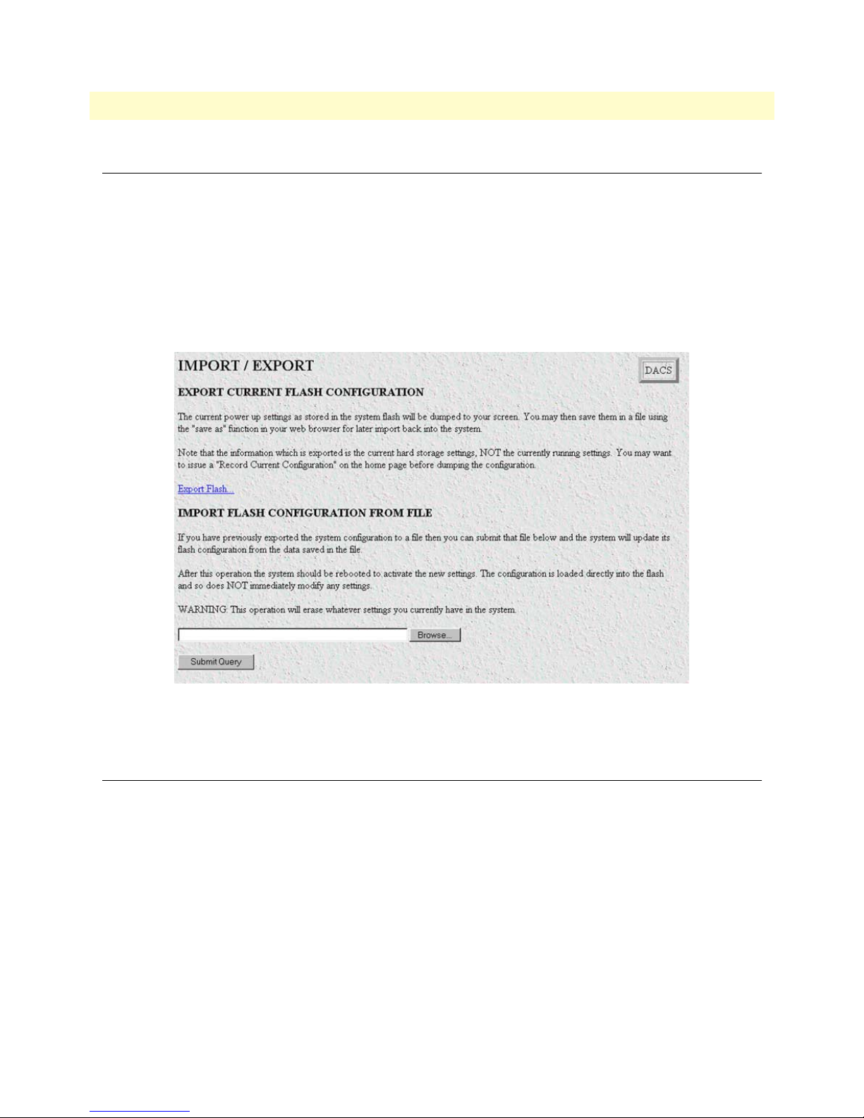
3 • Import/Export T1/E1 DACS Administrators’ Reference Guide
Introduction
The Import/Export function enables you to make a backup (or export) copy of your DACS’s configuration
parameters. By exporting the configurations, the saved files can quickly be loaded, or imported, into a replacement DACS—greatly speeding up the installation process should a DACS need replacing.
Note All actions for Import/Export require superuser access privileges.
To import or export a configuration, click on
Import/Export main window (see figure 6).
Import/Export under the Configuration Menu to display the
Export Configuration
Note The exported configuration file is a text-format file. Do not try, how-
ever to edit the operating characteristics contained in the file.
Note The parameters that will be exported are the power-up settings as
they are stored in flash memory and may not be the current operating
parameters. To ensure that you export the most current parameters,
go to
HOME, then click on the Record Current Configuration button
under
26 Introduction
Figure 6. Import/Export main window
Immediate Actions.
Page 29
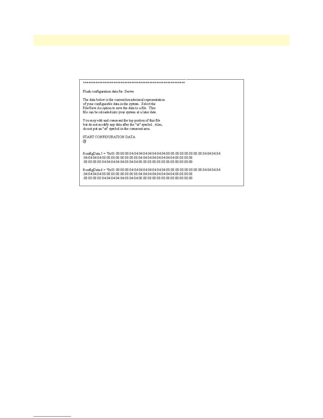
T1/E1 DACS Administrators’ Reference Guide 3 • Import/Export
To export the flash configuration, click on the Export Flash link on the Import/Export main page. The DACS
will display text configuration information resembling that shown in figure 7.
Figure 7. Typical DACS flash memory configuration data
Export Configuration 27
Page 30
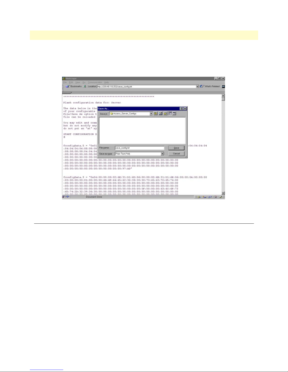
3 • Import/Export T1/E1 DACS Administrators’ Reference Guide
To save the displayed data as a text file, select the Save option on your browser (see figure 8). For example,
under Netscape, select
parameters to a text file. Select the location where you want the file stored, type a file name, and click
File > Save As. A dialog box will display enabling you to save the contents of the export
Save.
Figure 8. Saving the DACS flash memory configuration data as a text file
Import Configuration
To import a configuration file into the DACS, type the complete path and filename for the configuration file
you wish to load or click on the
ton (see figure 6 on page 26).
Upon successfully importing the file, the DACS will display Configuration Load Complete, indicating that the
new operating parameters have been loaded into flash memory.
Click on
HOME under the Configuration Menu, then click on the Hard Reset button under Immediate Actions.
Note Do not select Record Current Configuration after importing configu-
Browse… button to select the desired file, then click on the Submit Query but-
ration parameters because the configuration is imported directly into
non-volatile FLASH memory. Upon doing a Hard Reset the
imported configuration is now the operational software is RAM.
28 Import Configuration
Page 31

Chapter 4 Alarms
Chapter contents
Introduction..........................................................................................................................................................30
Displaying the alarms window...............................................................................................................................30
Alarm Response Outputs ................................................................................................................................32
Relay Response ..........................................................................................................................................32
Minor Alarm SYSLOG Priority (minSyslogPriority) .................................................................................32
Major Alarm SYSLOG Priority (majorSyslogPriority) ...............................................................................32
Minor Alarm SNMP Trap IP [address] (minorTrapIp) .............................................................................32
Major Alarm SNMP Trap IP [address] (majorTrapIp) ..............................................................................32
Temperature Threshold .............................................................................................................................32
Current Box Temperature .........................................................................................................................32
Clear All Alarms ........................................................................................................................................32
Alarms ............................................................................................................................................................32
Alarm ID ...................................................................................................................................................32
Alarm Name .............................................................................................................................................32
Alarm Time ...............................................................................................................................................33
Alarm Count .............................................................................................................................................33
Generate Alarm .........................................................................................................................................33
Clear Alarm ...............................................................................................................................................33
Alarm Parameters ............................................................................................................................................33
Types of Alarms ..............................................................................................................................................34
Modify Response—Configuring the alarm response system...................................................................................34
Relay Response ...............................................................................................................................................34
Minor Alarm Syslog Priority & Major Alarm Syslog Priority ..........................................................................34
Minor Alarm SNMP Trap IP [address] (minSyslogPriority) ...........................................................................34
Major Alarm SNMP Trap IP [address] (majorSyslogPriority) .........................................................................34
Temperature Threshold ..................................................................................................................................35
Modify Alarms—Configuring alarm severity levels ................................................................................................35
29
Page 32
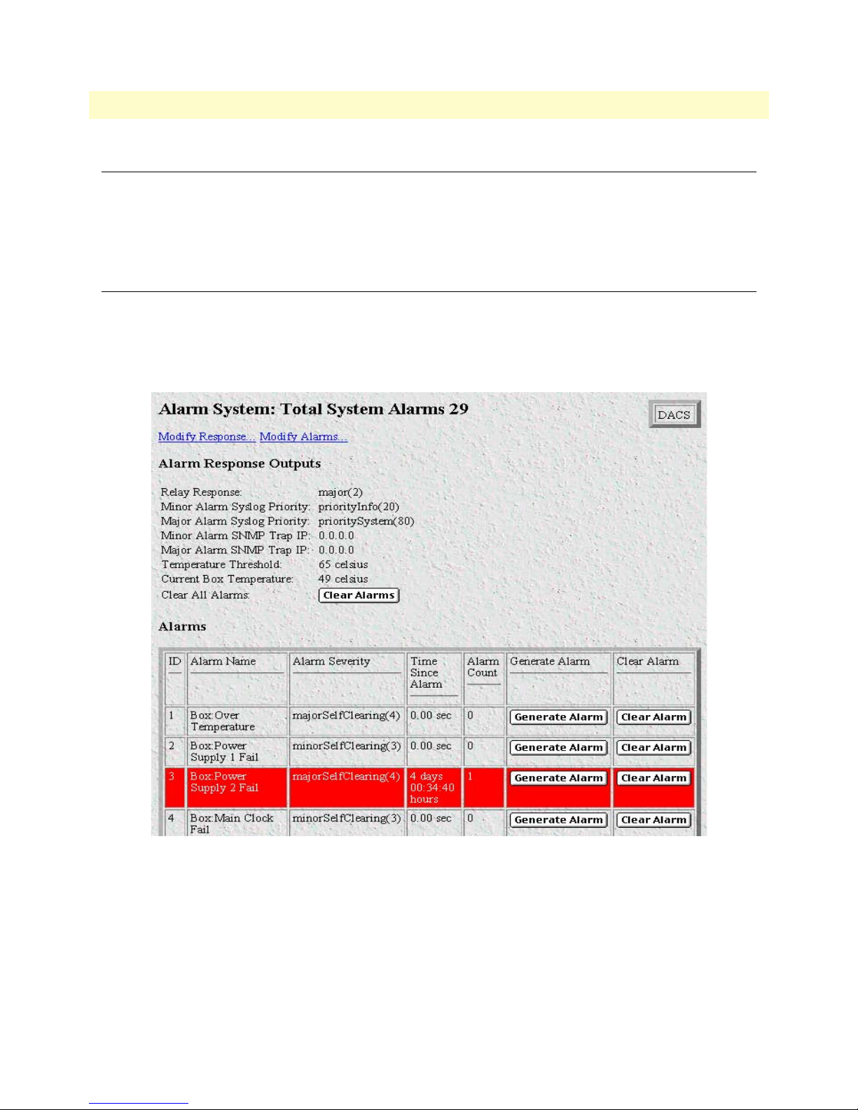
4 • Alarms T1/E1 DACS Administrators’ Reference Guide
Introduction
The DACS has an extensive alarm reporting system which enables users to configure, monitor, and test major
and minor alarms. The alarm system can be set to notify of equipment failures (for example, a power supply
failure) or T1/E1 port malfunctions. There are 83 alarms that can be configured by the system administrator to
generate alerts based on the condition of the DACS.
Displaying the alarms window
Click on Alarms under the Configuration Menu to display the Alarm System main window (figure 9).
Note The system administrator can manually generate a specific alarm for
testing purposes or clear the alarm counters from the main window.
30 Introduction
Figure 9. Alarms main window
Page 33
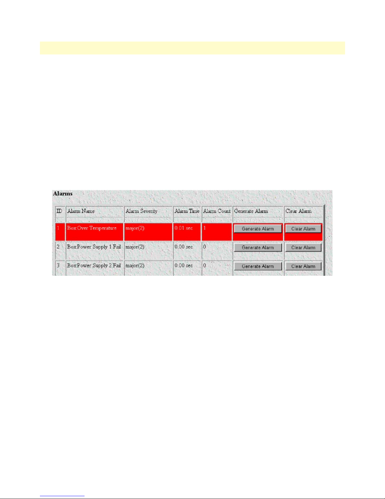
T1/E1 DACS Administrators’ Reference Guide 4 • Alarms
The T1/E1 DACS Multiplexer has four methods to notify an alarm condition:
1. Front panel LED—The front panel ALARM LED has three states that indicate the presence and severity
of an alarm. The states are:
- Off—No alarm present
- Solid—Minor alarm
- Flashing—Major alarm.
Note The POWER LED will flash if a power supply failure alarm is
present.
2. Administration web page indication—The Alarms window of the administration page uses red highlighting to indicate which items are in an alarm state (see figure 10).
Figure 10. Sample alarm indication
3. SYSLOG/SNMP—For external notification, the DACS can be configured to send a SYSLOG message or
an SNMP TRAP to an external management host. To configure the alarm response for either SNMP Traps
or SYSLOG messages, click on the
Alarm Response link (go to “Alarm Parameters” on page 33).
4. Alarm Relay—Located on the rear of the chassis, the Alarm Relay is a 3-position terminal block. The
Alarm Relay may be configured to indicate when a major alarm, a minor alarm or both major and minor
alarms occur. It may also be disabled. The 3-position terminal block numbers its pins from 1 to 3 from left
to right. When no alarms are indicated, pins 1 and 2 are normally closed and pins 2 and 3 are normally
open. Upon the occurrence of an alarm—the type is configured as major, minor, or both—pins 1 and 2 are
open and pins 2 and 3 are closed.
Besides enabling a user to view current alarm status, you may manually generate an alarm as a test and clear the
alarm time and count variables. The Alarms main window also contains links to the following:
• Modify Response—for configuring how the Alarm Response Outputs for notifying administrators of an
alarm (see “Alarm Parameters” on page 33)
• Modify Alarms—Clicking on this link takes you to a window where you can configure the importance or
severity of each individual alarm. The severity of the alarm type may generate a minor, major, minor selfclearing, or major self-clearing alarm. Any alarm type may be disabled. (“Modify Alarms—Configuring
alarm severity levels” on page 35)
Displaying the alarms window 31
Page 34

4 • Alarms T1/E1 DACS Administrators’ Reference Guide
Alarm Response Outputs
Alarm Response Outputs display the current setting for handling alarm notification via the different Alarm
Response Outputs. To change the Alarm Response Outputs parameters, refer to “Alarm Parameters” on
page 33.
Relay Response
The relay of the Alarm Port on the rear of the chassis will be activated when a major, minor, or both major and
minor alarm is generated. The Alarm Port may also be disabled.
Minor Alarm SYSLOG Priority (minSyslogPriority)
Sets the priority of the minor alarm SYSLOG message that will be generated upon the occurrence of a minor
alarm.
Major Alarm SYSLOG Priority (majorSyslogPriority)
Sets the priority of the major alarm SYSLOG message that will be generated upon the occurrence of a major
alarm.
Minor Alarm SNMP Trap IP [address] (minorTrapIp)
Displays the IP address of a SNMP management station for receiving the SNMP trap messages upon the
occurrence of an active minor alarm. The SNMP trap messages are sent in UDP datagrams. When the IP
address is set to 0.0.0.0, no trap messages will ever be sent.
Major Alarm SNMP Trap IP [address] (majorTrapIp)
The same function as the Minor Alarm Trap IP except for only the occurrence of active major alarms.
Temperature Threshold
An alarm will be generated when the box temperature exceeds this temperature value in degrees Celsius.
Current Box Temperature
The internal temperature in the box in degrees Celsius.
Clear All Alarms
Click on this button to clear all the alarms (that is, to reset all the alarms). This clearing action will, for all the
alarms, reset the alarm, reset Time Since Alarm to 0.00 seconds, and reset the Alarm Count to 0 (zero).
Alarms
This portion of the Alarms main window displays the alarm status table, where you can view current alarm status, manually generate an alarm as a test, and clear the alarm time and alarm count variables.
Alarm ID
This number identifies the alarm item.
Alarm Name
The alarm items are grouped into two categories: system and WAN trunk alarms. The system group category
lists DACS temperature and power supply status. The WAN category monitors the T1/E1/PRI ports for yellow and red alarms.
32 Displaying the alarms window
Page 35
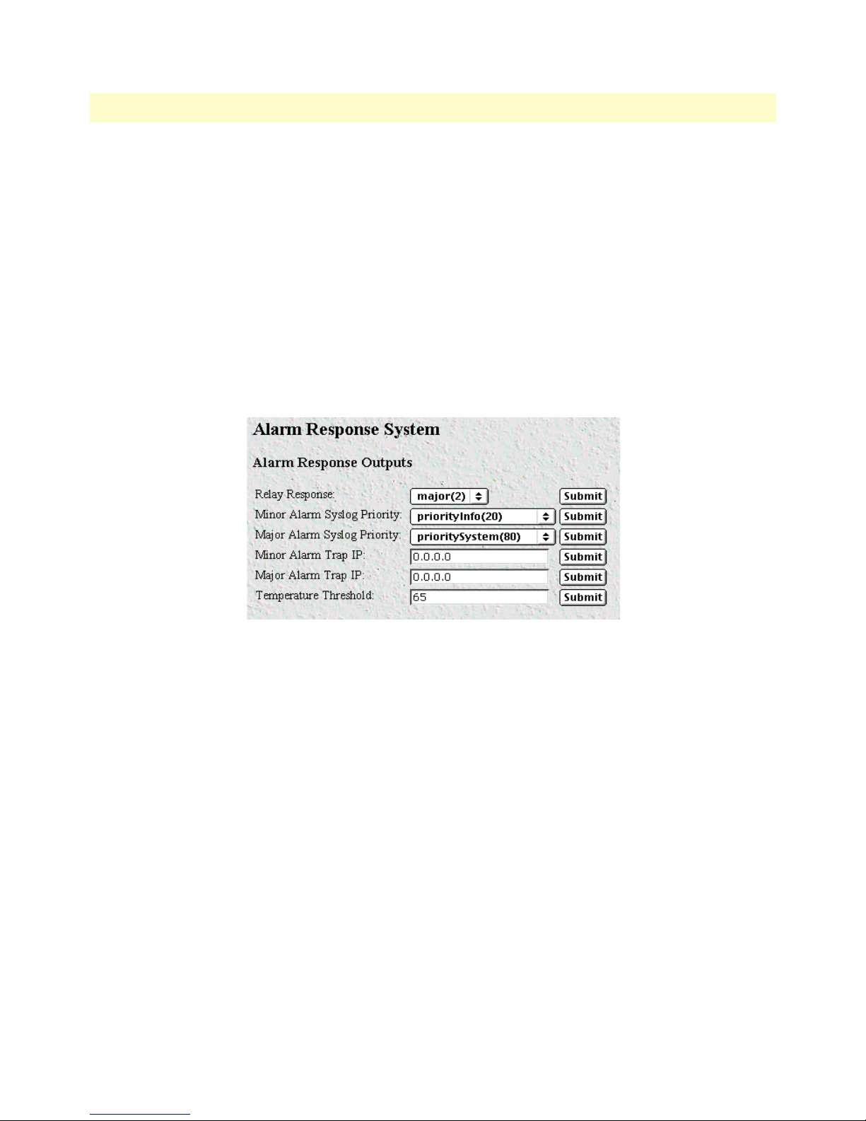
T1/E1 DACS Administrators’ Reference Guide 4 • Alarms
Alarm Time
The Alarm Time column displays the number of seconds the alarm has been activated.
Alarm Count
The Alarm Count column indicates how many times the alarm has occurred and is useful for monitoring selfclearing alarms.
Generate Alarm
For testing purposes, clicking the Generate Alarm button next to each alarm name will cause that alarm condition to be activated.
Clear Alarm
Clicking the Clear Alarm button resets the alarm to a non-alarm condition.
Figure 11. Alarm Response System window
Alarm Parameters
The Alarm Status Table on the Alarm System main page displays the current alarm status. You may also manually generate an alarm as a test and clear the alarm, the alarm time and the alarm count variables.
• Alarm ID—The Alarm ID identifies the alarm numerically. E.g., Alarm ID #2 identifies the alarm named
“Box: Power Supply I Failed.”
• Alarm Name—The alarm items are grouped into two categories: Box and WAN alarms. The Box alarm
group contains the alarms “Over Temperature” and “Power Supply Fail” for each of the two power supplies.
The WAN alarm group includes yellow and red alarms.
• Alarm Severity—For each alarm, it shows whether the alarm is disabled or configured to generate a major,
minor, major self-clearing, or minor self-clearing alarm.
• Time Since Alarm—Elapsed time since the alarm occurred.
• Alarm Count—The number of times this alarm has occurred since it has been cleared. It is also for moni-
toring self-clearing alarms.
• Generate Alarm—For testing a particular alarm, click on Generate Alarm. This activates the alarm as if the
actual trigger event had occurred.
Displaying the alarms window 33
Page 36

4 • Alarms T1/E1 DACS Administrators’ Reference Guide
• Clear Alarm—Clearing the alarm resets the alarm, resets Time Since Alarm to 0.00 seconds and resets
Alarm Count to 0 (zero).
Types of Alarms
• Box Alarm Group
- Box: Over Temperature—When the internal box temperature exceeds the temperature threshold under
Modify Response…, an alarm will be generated.
- Box: Power Supply I – II Fail—An alarm will be generated when a power supply fails.
• WAN Alarm Group
- WAN 1 – 4: Yellow Alarm—When a WAN port sees a yellow alarm, the specific WAN alarm will be sent.
- WAN 1 – 4: Red Alarm—When a WAN port sends a red alarm, the specific WAN alarm will be sent.
Modify Response—Configuring the alarm response system
The alarm response outputs refer to points of external notification. Note that the front panel Alarm LED and
the web administration pages will always indicate an occurrence of an active alarm. To configure each alarm
response output, click on
the alarm response output that you want to configure with the pull down menu. After configuring a specific
alarm response output, remember to click on Submit Query before going to the next alarm response output;
otherwise the change will not occur.
Modify Response. The Alarm Response System page appears (see figure 11). Choose
Relay Response
The relay may be set to go active for minor alarms, major alarms, or both. It may also be disabled with the
parameter “none.”
Minor Alarm Syslog Priority & Major Alarm Syslog Priority
When a minor/major alarm occurs, a message of the selected priority is sent to the Syslog engine. The Priority
levels are priorityDisable(100), prioritySystem(80), priorityService(60), priorityOddity(40), priorityInfo(20),
priorityDebug(10), and priorityVerbose(5). For more information on Syslog messages, refer to Chapter 16,
“System Log”.
Minor Alarm SNMP Trap IP [address] (minSyslogPriority)
Upon the occurrence of a minor alarm, an SNMP Trap message is sent to a host system (or a management station). This parameter is the IP address of the host running the SNMP Trap daemon. When the IP address is set
to 0.0.0.0 no SNMP Trap message will be sent.
Major Alarm SNMP Trap IP [address] (majorSyslogPriority)
This parameter functions in the same manner as the Minor Alarm SNMP Trap IP [address] except it applies to
major alarms. Upon the occurrence of a major alarm, an SNMP Trap message is sent to a host system (or a
management station). This parameter is the IP address of the host running the SNMP Trap daemon. When the
IP address is set to 0.0.0.0 no SNMP Trap message will be sent.
34 Modify Response—Configuring the alarm response system
Page 37

T1/E1 DACS Administrators’ Reference Guide 4 • Alarms
Temperature Threshold
An alarm message is generated when the internal box temperature exceeds this threshold value (degrees Celsius). You can change the threshold temperature, but we recommend that you use the factory default.
Modify Alarms—Configuring alarm severity levels
Clicking on Modify Alarms window (see figure 12) displays a table listing each individual alarm. From this
page you can configure the severity for each alarm (such as major, minor, major self-clearing, and minor selfclearing). Each alarm can be disabled as appropriate for your application.
There are 83 alarms that can be independently configured to generate alarm messages. Each alarm item can be
set for one of the following severity levels:
• Ignore(0)—Do not generate an alarm.
• Minor(1)—Generate a minor alarm that will not reset until the administrator manually clears it.
• Major(2)—Generate a major alarm that will not reset until the administrator manually clears it.
Modify Alarms—Configuring alarm severity levels 35
Figure 12. Modify Alarms settings window
Page 38

4 • Alarms T1/E1 DACS Administrators’ Reference Guide
• MinorSelfClearing(3)—Generate a minor alarm that automatically clears after a fixed period of time. If the
alarm condition has not ceased, the alarm will be automatically cleared, but another alarm will be immediately generated. If the alarm condition has ceased, the alarm will be automatically cleared after the same
fixed period of time.
• MajorSelfClearing(4)—Same as MinorSelfClearing(3) except that it is a Major alarm instead of Minor.
Note For maximum application flexibility, the administrator shall choose
which constitute major or minor alarm. Some examples of typical
major and minor alarms include:
- Box: Over Temperature—Major Alarm
- WAN 1: Red Alarm—MajorSelfClearing
- WAN 1: Yellow Alarm—MinorSelfClearing
To set an alarm, click on the drop-down menu for the desired alarm item, choose the new setting followed by
clicking on Submit Query.
36 Modify Alarms—Configuring alarm severity levels
Page 39

Chapter 5 DS0 Mapping
Chapter contents
Introduction..........................................................................................................................................................38
Displaying the DS0 Mapping window...................................................................................................................38
DACS Display Type .......................................................................................................................................38
Help (DACS help information) ......................................................................................................................39
Static Connection ...........................................................................................................................................39
ID .............................................................................................................................................................39
Device Type ..............................................................................................................................................39
Device Number .........................................................................................................................................39
Device Slots ..............................................................................................................................................40
Configuration .................................................................................................................................................40
37
Page 40
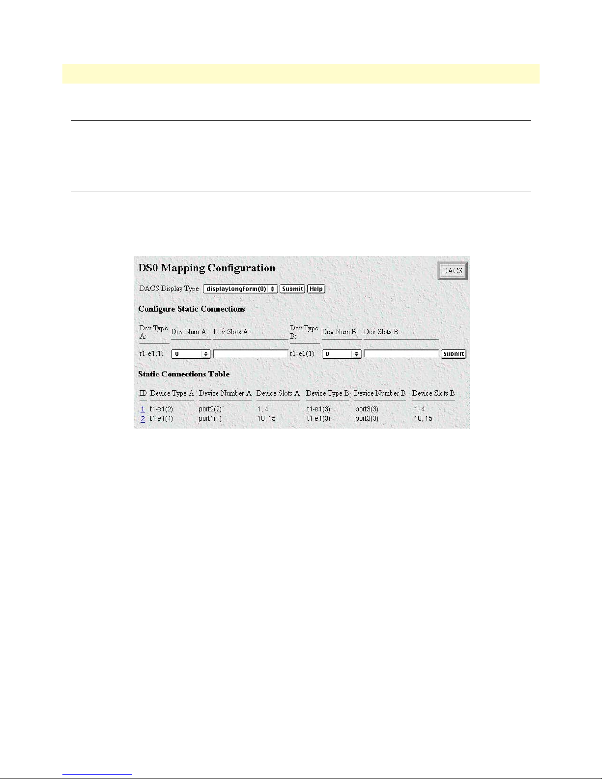
5 • DS0 Mapping T1/E1 DACS Administrators’ Reference Guide
Introduction
One of the remote locations is the CPE’s DACS. The second remote location is typically connected through
some WAN port’s time slots. For communication between these remote locations they shall be connected
together within the DACS. These connections are configured in the DS0 mapping window.
Displaying the DS0 Mapping window
Do the following:
1. Click on
DS0 Mapping under the Configuration Menu. The DS0 Mapping Configuration window dis-
plays (see figure 13).
Figure 13. DS0 Mapping Configuration window
The following sections describe the contents of the DS0 Mapping Configuration window.
DACS Display Type
You can configure or map the static connections by using the Long Format or the Command Line Format.
• displayLongForm(0)—This is the easiest to use by selecting the options from the pull-down menus.
• displayCliForm(1)—If you prefer the command line format, select displayCliForm(1) and click on the Sub-
mit Query button. Consult the following sections for the format of the command line.
38 Introduction
Page 41

T1/E1 DACS Administrators’ Reference Guide 5 • DS0 Mapping
Help (DACS help information)
Clicking on the Help button displays the DACS Help Information window (see figure 14). The purpose of
this window is to help the user learn how to add DS0 connections using the DACS HTML pages. This window define all of the parameters available within this web page. If you are using the Command Line Format to
make connections, scroll down the window to the heading
Command Line Format. The information contained
in the Help window is also covered in this chapter.
Figure 14. Example DACS Help Information window
Static Connection
Pull Down Menus
Each pull down window signifies part of a connection. Each connection is made up of an "A" side and a "B"
side. These names have been arbitrarily chosen and do not signify the direction that data will travel. All data
will be bi-directional. There are three parameters that need to be defined for each connection, they are:
• Device Type
• Device Number
• Device Slots
ID
Then ID number identifies each mapping with a unique number. The number is automatically assigned
sequentially when a static connection is entered. The ID number begins at “1.”
Device Type
The Device Type specifies the physical interface that you will be connecting. Within the 2604 the user has the
option of selecting either a T1/E1 WAN line or a DACS. While the one side may be a T1/E1 WAN line and
the other a DACS, note that both sides of the connection can be T1/E1 or both sides can be iDSL. The two
Device Types are t1-e1(1) and t1-e1(2).
Device Number
The next step in creating a connection through the DACs is to select the port that you would like to use. This
corresponds to the Port Number for the devices selected in the previous step. For example, if you would like to
make a connection to port 3 (referring to DACS #3), then select "Port 3" in the "Device Number" field. Note
that there are only four t1-e1 ports so you may not select t1-e1 ports 5 - 24. This will generate an error in the
system. Since there are 24 DACSs within the 2604, you may choose any of the 24 ports.
Displaying the DS0 Mapping window 39
Page 42

5 • DS0 Mapping T1/E1 DACS Administrators’ Reference Guide
Device Slots
The "slots" input identifies the DS0 channels—each DS0 channel is 64 kbps—that you would like to connect. Each time slot in a T1 or E1 WAN port has 24 or 31 DS0 channels, respectively. When selecting the
slots you must select the same number of slots on the "A" and "B" side of the connection. The slots are selected
by entering a string that represents the slots. For a WAN port configured as a T1, the available slots are numbered from 1 - 24. For a WAN port configured as an E1, the available slots are 1 - 31. The following notation
should be used for entering the slots. Several examples are given below.
• dash: (-) 1 - 4
• comma: (,) 1,4,9
• combo: 1 - 2, 3,6 - 7
For example, to connect a T1 Port using timeslots 1,2, 5, 6, 7, and 15, you can input any of the following
strings:
1,2, 5-7, 15
1 - 2, 5,6,7,15
1 - 2, 5 - 6, 7, 15
Configuration
The user can make connections in the box using two different methods. The easiest way is by using the pull
down windows provided. But the user can also add connection using the command line format by entering a
text string. To input a static connection into the box using the text string. Use the following convention:
• DeviceA:PortA:SlotsA/DeviceB:PortB:SlotsB
Device Options - The interface that you would like to select
t1-e1
Port Options - The Port Number (starting at 1) may be one of the four WAN ports. To configure Slots
(DS0 channels), choose the slots that you would like to use. The following notations are allowed:
1) dash (-): 1 - 4
2) comma (,): 1,4,9
3) combination of dashes and commas: 1 - 2, 3,6 - 7
Example: To connect a T1 line, Port 1, timeslots 1 and 2 to a T1 line, Port 2, timeslots 5 and 6, input the
following string:
t1-e1:1:1-2/t1-e1:2:5-6
40 Displaying the DS0 Mapping window
Page 43

Chapter 6 Clocking
Chapter contents
Introduction..........................................................................................................................................................42
Configuring the System Clock Settings..................................................................................................................42
Main Reference (daxClockMainRef) ...............................................................................................................42
Fallback Reference (daxClockFallbackRef) ......................................................................................................43
Clock Status (daxClockFailure) .......................................................................................................................43
41
Page 44

6 • Clocking T1/E1 DACS Administrators’ Reference Guide
Introduction
Click on Clocking in the Configuration Menu to display the System Clocking Configuration main window
(see figure 15).
Figure 15. System Clocking Configuration window
The Clocking window is where the primary and secondary clocking sources that synchronize all DS0 channels
are configured. The DACS uses a single clock source for all DS0 channels. You select the clock for the DS0
channels from the following clock sources:
• An internal oscillator
• Any of the WAN ports
• An external clock (accessed via the Ext. Clock 3-position terminal block located on the rear panel of the
DACS.”
Main Reference setting determines the clock source if this source is operational. If the Main Reference
The
clock source fails, the
Fallback Reference becomes the clock source to synchronize all DS0 channels. The
clock source is the system clock for the entire DACS.
Configuring the System Clock Settings
The following sections describe configuring the clock settings.
Main Reference (daxClockMainRef)
The Main Reference and Fallback Reference parameters have the same selections for system clock. Make sure
you choose different clock sources for the Main Reference and Fallback Reference. The following settings
are available:
• none(0)—No clock selection.
• wan-1(1)—WAN port #1 is the clock source
• wan-2(2)—WAN port #2 is the clock source
• wan-3(3)—WAN port #3 is the clock source
• wan-4(4)—WAN port #4 is the clock source
• wan-5(5)—N/A
• wan-6(6)—N/A
• wan-7(7)—N/A
• wan-8(8)—N/A
42 Introduction
Page 45

T1/E1 DACS Administrators’ Reference Guide 6 • Clocking
• netref-1(101)—N/A
• netref-2(102)—N/A
• internal(200)— The internal free-running oscillator is the clock source.
• external(300)—The external clock source connected to the 3-position terminal block on the rear of the
2604 DACS is the clock source
Fallback Reference (daxClockFallbackRef)
The fallback reference enables the configuration of a back-up clock reference should the main reference fail.
The
Main Reference and Fallback Reference parameters have the same selections for system clock. Make sure
you choose different clock sources for the Main Reference and Fallback Reference. The fallback reference settings are the same as those described in section “Main Reference (daxClockMainRef )” on page 42.
Clock Status (daxClockFailure)
The clock status indicates alarm conditions relating to the system clock. If there are no alarms, the Clocking
page will indicate No Alarm (see figure 15 on page 42). If an alarm condition exists, an Alarms Present message
will be displayed along with one of the following failure descriptions.
• no-failures(0)—No alarms present
• main-ref-fail(1)—The main clock reference has failed
• fallback-ref-fail(2)—The fall back clock reference has failed
Configuring the System Clock Settings 43
Page 46

6 • Clocking T1/E1 DACS Administrators’ Reference Guide
44 Configuring the System Clock Settings
Page 47

Chapter 7 Ethernet
Chapter contents
Introduction..........................................................................................................................................................46
Ethernet statistics...................................................................................................................................................46
Alignment Errors (dot3StatsAlignmentErrors) ................................................................................................46
FCS Errors (dot3StatsFCSErrors) ...................................................................................................................46
Single Collision Frames (dot3StatsSingleCollision Frames) .............................................................................46
Multiple Collision Frames (dot3StatsMultipleCollisionFrames) ......................................................................47
SQE Test Errors (dot3StatsSQETestErrors) ....................................................................................................47
Deferred Transmissions (dot3StatsDeferredTransmissions) .............................................................................47
Late Collisions (dot3StatsLateCollisions) ........................................................................................................47
Excessive Collisions (dot3StatsExcessiveCollisions) .........................................................................................47
Other Errors (dot3StatsInternalMacTransmitErrors) ......................................................................................47
Carrier Sense Errors (dot3StatsCarrierSenseErrors) .........................................................................................47
Received Frames Too Long (dot3StatsFrameTooLongs) .................................................................................47
Other Received Errors (dot3StatsInternalMacReceiveErrors) ..........................................................................48
Chip Set ID (dot3StatsEtherChipSet) .............................................................................................................48
45
Page 48

7 • Ethernet T1/E1 DACS Administrators’ Reference Guide
Introduction
The DACS provides management and statistical information in the Ethernet window (see figure 16). Most of
the descriptions for these MIB variables are from RFC 1643. Detailed information regarding the SNMP MIB
II variables may be downloaded from RFC 1643, Definitions of Managed Objects for the Ethernet-like Interface
Types.
Figure 16. Ethernet window
Click on Ethernet under the Configuration Menu to monitor Ethernet statistics.
Ethernet statistics
Alignment Errors (dot3StatsAlignmentErrors)
A count of frames received that are not an integral number of octets in length and do not pass the FCS check.
The count represented by an instance of this object is incremented when the alignmentError status is returned
by the MAC service to the LLC (or other MAC user). Received frames for which multiple error conditions
obtain are, according to the conventions of IEEE 802.3 Layer Management, counted exclusively according to
the error status presented to the LLC.
FCS Errors (dot3StatsFCSErrors)
A count of frames received that are an integral number of octets in length but do not pass the FCS check. The
count represented by an instance of this object is incremented when the frameCheckError status is returned by
the MAC service to the LLC (or other MAC user). Received frames for which multiple error conditions obtain
are, according to the conventions of IEEE 802.3 Layer Management, counted exclusively according to the
error status presented to the LLC."
Single Collision Frames (dot3StatsSingleCollision Frames)
A count of successfully transmitted frames for which transmission is inhibited by exactly one collision. A
frame that is counted by an instance of this object is also counted by the corresponding instance of either the
46 Introduction
Page 49

T1/E1 DACS Administrators’ Reference Guide 7 • Ethernet
ifOutUcastPkts, ifOutMulticastPkts, or ifOutBroadcastPkts, and is not counted by the corresponding instance
of the dot3StatsMultipleCollisionFrames object."
Multiple Collision Frames (dot3StatsMultipleCollisionFrames)
The number of successfully transmitted frames for which transmission is inhibited by more than one collision. A frame that is counted by an instance of this object is also counted by the corresponding instance of
either the ifOutUcastPkts, ifOutMulticastPkts, or ifOutBroadcastPkts, and is not counted by the corresponding instance of the dot3StatsSingleCollisionFrames object."
SQE Test Errors (dot3StatsSQETestErrors)
A count of times that the SQE TEST ERROR message is generated by the PLS sublayer. The SQE TEST
ERROR message is defined in section 7.2.2.2.4 of ANSI/IEEE 802.3-1985 and its generation is described in
section 7.2.4.6 of the same document."
Deferred Transmissions (dot3StatsDeferredTransmissions)
The number of times for which the first transmission attempt is delayed because the medium is busy. This
number does not include frames involved in collisions.
Late Collisions (dot3StatsLateCollisions)
The number of times that a collision is detected later than 512 bit-times into the transmission of a packet. Five
hundred and twelve bit-times corresponds to 51.2 microseconds on a 10 Mbps system. A (late) collision
included in a count of late collisions is also considered as a (generic) collision for purposes of other collisionrelated statistics.
Excessive Collisions (dot3StatsExcessiveCollisions)
The number of frames in which transmission failed due to excessive collisions.
Other Errors (dot3StatsInternalMacTransmitErrors)
The number of frames for which transmission fails due to an internal MAC sublayer transmit error. A frame is
only counted if it is not counted by the corresponding instance of either the dot3StatsLateCollisions object,
the dot3StatsExcessiveCollisions object, or the dot3StatsCarrierSenseErrors object. The precise meaning of the
count represented by an instance of this object is implementation-specific. In particular, an instance of this
object may represent a count of transmission errors on a particular interface that are not otherwise counted.
Carrier Sense Errors (dot3StatsCarrierSenseErrors)
The number of times that the carrier sense condition was lost or never asserted when attempting to transmit a
frame. The is incremented at most once per transmission attempt, even if the carrier sense condition fluctuates
during a transmission attempt."
Received Frames Too Long (dot3StatsFrameTooLongs)
The number of frames received that exceed the maximum permitted frame size. The count is incremented
when the frameTooLong status is returned by the MAC service to the LLC (or other MAC user). Received
frames for which multiple error conditions obtain are, according to the conventions of IEEE 802.3 Layer Management, counted exclusively according to the error status presented to the LLC."
Ethernet statistics 47
Page 50

7 • Ethernet T1/E1 DACS Administrators’ Reference Guide
Other Received Errors (dot3StatsInternalMacReceiveErrors)
The number of frames in which reception fails due to an internal MAC sublayer receive error. A frame is only
counted if it is not counted by either the dot3StatsFrameTooLongs object, the dot3StatsAlignmentErrors
object, or the dot3StatsFCSErrors object. The precise meaning of the count represented by an instance of this
object is implementation-specific. In particular, an instance of this object may represent a count of receive
errors on a particular interface that are not otherwise counted."
Chip Set ID (dot3StatsEtherChipSet)
Identifies the chipset to implement the Ethernet interface. The chipset ID identifies the chipset which gathers
the transmit and receive statistics and error indications.
48 Ethernet statistics
Page 51

Chapter 8 Filter IP
Chapter contents
Introduction..........................................................................................................................................................50
Defining a filter .....................................................................................................................................................50
Name (filterIpName) ......................................................................................................................................52
Direction (filterIpDirection) ...........................................................................................................................52
Action (filterIpAction) ....................................................................................................................................52
Source IP (filterIpSourceIp) ............................................................................................................................52
Source IP Mask (filterIpSourceMask) ..............................................................................................................52
Destination IP (filterIpDestinationIp) .............................................................................................................52
Destination Mask (filterIpDestinationMask) ...................................................................................................53
Source Port (FilterIpSourcePort) .....................................................................................................................53
Action (filterIpSourcePortCmp) ......................................................................................................................53
Destination Port (filterIpDestinationPort) ......................................................................................................53
Action (filterIpDestinationPortCmp) ..............................................................................................................53
Protocol (filterIpProtocol) ...............................................................................................................................53
TCP Established (filterIpTcpEstablished) .......................................................................................................53
49
Page 52

8 • Filter IP T1/E1 DACS Administrators’ Reference Guide
Introduction
The DACS software provides an IP filtering system that enables you to set up security for the internal management system.
Each filter is a defined list of parameters based upon attributes in the IP, TCP, and UDP headers. There are two
major steps to filter creation: first defining the filter, then applying it to a user connection. The same filter can
be shared by several users.
The DACS enables 20 separate filters to be defined, of which up to 10 can be used during a single user connection. Since the IP connections in the 2604 are only for the superuser and the monitor user, these will be the
only two users. The application of the filters is done on the Filter IP main web page.
Click on
Filter IP under the Configuration Menu to display the FIlter IP main window (see figure 17).
Figure 17. Filter IP main window
Defining a filter
This section gives a brief summary on defining a filter. For a complete discussion with filter examples, see the
final section.
To define a new filter, select an ID number and a name, then click on the Submit Query button to submit the
request. The ID number and name must not already exist in the IP FILTER list, and the number must be an
integer between 1 and 20. To delete a filter, enter just the ID number without a name and click on the Submit
Query button.
Note Block filters take priority, therefore any applied and matching block
filters will drop the packet. Next, pass filters are examined, if PASS filters have been defined, then at least one of them must match or else
the packet will be dropped. After the block and pass filters are examined, the WRAP filter, if it exists, will be applied.
50 Introduction
Page 53

T1/E1 DACS Administrators’ Reference Guide 8 • Filter IP
After entering an ID number and name, click on the name of the filter to display the filter parameters window
(see figure 18).
Figure 18. Filter IP parameters window
The configurable filter parameters are :
• Name (filterIpName)
• Direction (filterIpDirection)
• Action (filterIpAction)
• Source IP (filterIpSourceIp)
• Source IP Mask (filterIpSourceMask)
• Destination IP (filterIpDestinationIp)
• Destination Mask (filterIpDestinationMask)
• Source Port (FilterIpSourcePort)
• Action (filterIpSourcePortCmp)
• Destination Port (filterIpDestinationPort)
• Action (filterIpDestinationPortCmp)
• Protocol (filterIpProtocol)
• TCP Established (filterIpTcpEstablished)
Note Any changes to a filter take effect immediately upon clicking Submit
Query. This can aid in troubleshooting a filter profile while the user
is online.
Defining a filter 51
Page 54

8 • Filter IP T1/E1 DACS Administrators’ Reference Guide
The following sections provide detailed descriptions of the configurable filter IP parameters.
Name (filterIpName)
This is the name of the filter
Direction (filterIpDirection)
Specifies the direction of the filter (that is, whether it applies to data packets inbound or outbound from the
DACS). The filter only applies to the Superuser and the Monitor Users through the Ethernet interface. (Since
the DACS and WAN connections function as a transparent pipe, neither of the two users can utilize these
interfaces, only the Ethernet interface.) The following options are available:
• inactive(0)—Disables filter operation
• inbound(1)—Relates to packets coming into the DACS
• outbound(2)—Relates to packets leaving the DACS
• both(3)—Specifies both inbound and outbound operation
Action (filterIpAction)
Specifies the action to effect the packet. The action decides whether to block or pass the packet. The following
options are available:
• pass(0)—If pass is selected, checking will continue on to other filters until either a match occurs, a block
occurs, or there are no more filters remaining to check.
Note If there are any applied PASS filters, then at least one of them must
match or the packet will be dropped.
• block(1)—If a filter has block set and the filter matches the block, the packet is discarded and no further
processing is done.
• wrap(2)—All packets received on the specified link will be encapsulated in an extra IP header as defined in
RFC2003. The destination IP address of the wrapper is given by the destination IP setting in the filter. The
source IP address of the wrapper is the ethernet address of the DACS.
All wrap filters are inbound only.
Source IP (filterIpSourceIp)
This is the Source IP address in the IP header, it is used when comparing a packet’s source address.
Source IP Mask (filterIpSourceMask)
This is the Source IP Mask (filterIpSourceMask) used when comparing a packet’s source address. Bit positions
that are set to 1 will be compared and 0’s will be ignored. Thus, a setting of 0.0.0.0 will have the effect of disabling source IP address comparison.
Destination IP (filterIpDestinationIp)
This is the destination IP address in the IP header used when comparing a packet’s destination address.
52 Defining a filter
Page 55

T1/E1 DACS Administrators’ Reference Guide 8 • Filter IP
Destination Mask (filterIpDestinationMask)
This is the destination mask used when comparing a packet’s destination address. Bit positions that are set to 1
will be compared and 0’s will be ignored. Thus, a setting of 0.0.0.0 will have the effect of disabling destination
IP address comparison.
Source Port (FilterIpSourcePort)
Specifies the source port number (TCP or UDP) that the access server DACS compares. The source port
Action (see Action (filterIpSourcePortCmp) next) action will determines how the source port is treated.
whether the source port in the IP packet is not compared, equal, less than, or greater than the Source Port designated in the filter.
Action (filterIpSourcePortCmp)
Specifies the Action (filterIpSourcePortCmp) that the DACS compares. The source port action determines
whether the source port in the IP packet is not compared, equal, less than, or greater than the Source Port designated in the filter.
• noCompare(0) – No Comparison to the source port in the IP packet.
• equal(1)—The port in the source IP packet is the same
• lessThan(2)—The port in the source IP packet is less than
• greaterThan(3)—The port in the source IP packet is greater than
Destination Port (filterIpDestinationPort)
Specifies the destination port number which the DACS compares. The destination action functions similarly
to the Source Port and its Action defined above.
Action (filterIpDestinationPortCmp)
Specifies the action (TCP or UDP) which the DACS compares. The destination action will determine how the
destination port is treated.
• noCompare(0)—No Comparison to the destination port in the IP packet.
• equal(1)—The port in the destination IP packet Is the same
• lessThan(2)—The port in the destination IP packet is less than
• greaterThan(3)—The port in the destination IP packet is greater than
Protocol (filterIpProtocol)
Specifies the IP Protocol number to use for filtering. Some examples of protocol numbers are 1 for ICMP; 6
for TCP; and 17 for UDP. A list of protocol numbers can be found in RFC 1340. A setting of 0 disables processing based on protocol number.
TCP Established (filterIpTcpEstablished)
Specifies whether the filter should match only those packets which indicate in the TCP header flags that the
connection is established. The following choices are available:
• anyPackets(0)—Applies the filter to all packets
• onlyEstablishedConnections(1)—Only applies the filter to established TCP connections
Defining a filter 53
Page 56

8 • Filter IP T1/E1 DACS Administrators’ Reference Guide
54 Defining a filter
Page 57

Chapter 9 ICMP
Chapter contents
Introduction..........................................................................................................................................................56
Block ICMP redirects (boxBLockIcmpRedirects) ..................................................................................................56
ICMP Receive/Send Messages window..................................................................................................................56
Total Received (icmpInMsgs) .........................................................................................................................56
Total Sent [imcpOutMsgs] .............................................................................................................................57
w/Errors (icmpInErrors, icmpOutErrors) ........................................................................................................57
wo/Errors [icmpOutErrors] ............................................................................................................................57
Destinations Unreachable (IcmpInDestUnreachs, IcmpOutDestUnreachs) ....................................................57
Times Exceeded (icmpInTimeExcds, icmpOutTimeExcds) ............................................................................57
Parameter Problems (icmpInParmProbs, icmpOutParmProbs) .......................................................................57
Source Quenchs (icmpInSrcQuenchs, icmpOutSrcQuenchs) .........................................................................57
Redirects (icmpInRedirects, icmpOutRedirects) .............................................................................................58
Echos (icmpInEchos, icmpOutEchos) .............................................................................................................58
Echo Replys (icmpInReps, icmpOutReps) ......................................................................................................58
Time Stamps (icmpInTimestamps, icmpInTimestamps) .................................................................................58
Time Stamp Replys (icmpInTimestampsReps) (icmpOutTimestampsReps) ...................................................58
Address Mask Requests (icmpInAddrMasks) (icmpOutAddrMasks) ...............................................................58
Address Mask Replys (icmpInAddrMasksReps) (icmpOutAddrMasksReps) ....................................................58
55
Page 58

9 • ICMP T1/E1 DACS Administrators’ Reference Guide
Introduction
When networking problems or undesirable conditions occur, the ICMP protocol is used for communicating
control or error information plus testing. The statistics listed on the DACS ICMP window (see figure 19) comprise those contained in RFC 792—Internet Control Message Protocol (ICMP). Implementation of the ICMP
group is mandatory for all TCP/IP networks. RFC 1312—ICMP Group of MIB-II Variables—provides the
definitions of these variables. It is important to remember that any RFC can be superseded by a newer.
Figure 19. ICMP window
Click on ICMP under the Configuration Menu to monitor DACS ICMP statistics.
Block ICMP redirects (boxBLockIcmpRedirects)
The two options for “Block ICMP Redirects” either allow the reception of ICMP Redirect messages [allowredirects(0)] or block the reception of ICMP Redirect messages [stopredirects(1)]. The recommended configuration is to block the ICMP redirect messages because in some instances they could alter the routing table with
undesirable effects, which is considered a breach of security.
ICMP Receive/Send Messages window
The ICMP window displays the ICMP message counters. ICMP messages are displayed in the window as columns comprising two types of messages:
• Messages received by the DACS (InMibVariable)
• Messages sent by the DACS (OutMibVariable)
The numbers following the parameters can be a good source of what is happening on the network to point out
potential problems. Both gateways (routers) and hosts can send ICMP messages.
Total Received (icmpInMsgs)
The total number of ICMP messages which the 2604 DACS has received. Note that this counter includes all
those counted by icmpInErrors (see “w/Errors (icmpInErrors, icmpOutErrors)” on page 57).
56 Introduction
Page 59

T1/E1 DACS Administrators’ Reference Guide 9 • ICMP
Total Sent [imcpOutMsgs]
Similar to icmpInMsgs, Total Sent represents the total number of ICMP messages which the 2604 has
attempted to send. This variable includes all ICMP messages counted by icmpOutErrors (see “wo/Errors [icmpOutErrors]”).
w/Errors (icmpInErrors, icmpOutErrors)
The number of ICMP messages which the Model 2604 received/sent but having ICMP-specific errors (for
example, bad ICMP checksums, bad length, or non-routable errors).
wo/Errors [icmpOutErrors]
The number of ICMP messages which the Model 2604 did not send due to problems discovered within ICMP
such as a lack of buffers. It does not include errors discovered outside the ICMP layer like the inability of IP to
route the resultant datagram.
Destinations Unreachable (IcmpInDestUnreachs, IcmpOutDestUnreachs)
The number of ICMP destination unreachable messages received/sent. For instance, if the information in a
gateway’s routing table determines that the network specified in a packet is unreachable, the gateway will send
back an ICMP message stating that the network is unreachable. The following conditions will send back an
unreachable message:
• The network is unreachable
• The host is unreachable
• The protocol is not available to the network
• The port on the host is unavailable. a specified source route failed
• A packet must be fragmented (that is, broken up into two or more packets) but the packet was sent anyway
with instructions not to be fragmented.
Times Exceeded (icmpInTimeExcds, icmpOutTimeExcds)
The number of ICMP time exceeded messages received/sent. Each time a packet passes through a gateway, that
gateway reduces the time-to-live (TTL) field by one. The default starting number is defined under the IP section. If the gateway processing a packet finds that the TTL field is zero it will discard the packet and send the
ICMP time exceeded message. Time exceeded will also be incremented when a host which is reassembling a
fragmented packet cannot complete the reassembly due to missing packets within its time limit. In this case,
ICMP will discard the packet and send the time exceeded message.
Parameter Problems (icmpInParmProbs, icmpOutParmProbs)
The number of ICMP parameter problem messages received/sent. If while processing a packet, a gateway or
host finds a problem with one or more of the IP header parameters which prohibits further processing, the gatway or host will discard the packet and return an ICMP parameter problem message. One potential source of
this problem may be with incorrect or invalid arguments in an option. ICMP sends the parameter problems
message if the gateway or host has discarded the whole packet.
Source Quenchs (icmpInSrcQuenchs, icmpOutSrcQuenchs)
The number of ICMP source quench messages received/sent. A gateway will discard packets if it cannot allocate the resources, such as buffer space, to process the packet. If a gateway discards the packet, it will send an
ICMP Receive/Send Messages window 57
Page 60

9 • ICMP T1/E1 DACS Administrators’ Reference Guide
ICMP source quench message back to the sending device. A host may send this messages if packets arrive too
fast to be processed or if there is network congestion. The source quench message is a request to reduce the rate
at which the source is sending traffic. If the DACS receives a source quench, it will wait for acknowledgement
of all outstanding packets before sending more packets to the remote destination. Then it will begin sending
out packets at an increasing rate until the connection is restored to standard operating conditions.
Redirects (icmpInRedirects, icmpOutRedirects)
The number of ICMP redirect messages received/sent. A gateway sends a redirect message to a host if the network gateways find a shorter route to the destination through another gateway.
Echos (icmpInEchos, icmpOutEchos)
The number of ICMP echo request messages received/send. The ICMP echo is used whenever one uses the
diagnostic tool ping. Ping is used to test connectivity with a remote host by sending regular ICMP echo
request packets and then waiting for a reply. Received echos (icmpInEchos) will increment when the DACS is
pinged.
Echo Replys (icmpInReps, icmpOutReps)
The number of ICMP echo reply messages received/sent. An echo reply is a response to an echo request. Send
echos (icmpOutEchos) will increment when the DACS sends an echo reply message in response to a ping.
Time Stamps (icmpInTimestamps, icmpInTimestamps)
The number of ICMP time stamp messages received/sent. Time stamp and time stamp replies were originally
designed into the ICMP facility to allow network clock synchronization. Subsequently, a new protocol—Network time protocol (NTP) has taken over this function. Normally, this number will be zero.
Time Stamp Replys (icmpInTimestampsReps) (icmpOutTimestampsReps)
The number of ICMP timestamp reply messages received/sent. This message is part of a time stamp (see “Time
Stamps (icmpInTimestamps, icmpInTimestamps)”) request. Normally, this number will be zero.
Address Mask Requests (icmpInAddrMasks) (icmpOutAddrMasks)
The number of ICMP address mask request messages received/sent. this message is generally used for diskless
workstations which use this request at boot time to obtain their subnet mask. This number will increase if there
are hosts on the network which broadcast these requests.
Address Mask Replys (icmpInAddrMasksReps) (icmpOutAddrMasksReps)
The number of ICMP address mask reply messages received/sent. Normally, this number will be zero.
58 ICMP Receive/Send Messages window
Page 61

Chapter 10 IP
Chapter contents
Introduction..........................................................................................................................................................61
IP main window ....................................................................................................................................................61
Forwarding (ipForwarding) .............................................................................................................................62
Default Time-To-Live (ipDefaultTTL) ...........................................................................................................62
Total Datagrams Received (ipInReceives) .......................................................................................................62
Discarded for Header Errors (ipInHdrErrors) .................................................................................................62
Discarded for Address Errors (ipInAddrErrors) ...............................................................................................62
Forwarded Datagrams (ipForwDatagrams) .....................................................................................................62
Discarded for Unknown Protos (ipInUnknownProtos) ...................................................................................62
Discarded w/No Errors (ipInDiscards) ............................................................................................................62
Total Deliveries (ipInDelivers) ........................................................................................................................63
Out Requests (ipOutRequests) ........................................................................................................................63
Out Discards (ipOutDiscards) ........................................................................................................................63
Discarded for No Routes (ipOutNoRoutes) ....................................................................................................63
Reassembly Timeout (ipReasmTimeout) ........................................................................................................63
# of Reassembled Fragments (ipReasmReqds) .................................................................................................63
# Successfully Reassembled (ipReasmOKs) .....................................................................................................63
Reassembly Failures (ipReasmFails) .................................................................................................................63
# Fragmented OK (ipFragOKs) ......................................................................................................................64
# Fragmented Failed (ipFragFails) ...................................................................................................................64
# Fragments Created (ipFragCreates) ..............................................................................................................64
# Valid but Discarded (ipRoutingDiscards) ....................................................................................................64
Modify ..................................................................................................................................................................64
Forwarding (ipForwarding) .............................................................................................................................64
Default Time-To-Live (ipDefaultTTL) ...........................................................................................................64
Addressing Information.........................................................................................................................................65
IP addressing Information Details ...................................................................................................................65
Entry Interface Index (ipAdEntIfIndex) ....................................................................................................65
Entry Subnet Mask (ipAdEntNetMask) ....................................................................................................65
Entry Broadcast Address (ipAdEntBcastAddr) ...........................................................................................65
Entry Reassembly Maximum Size (ipAdEntReasmMaxSize) .....................................................................65
Routing Information .............................................................................................................................................66
Destination (ipRouteDest) ..............................................................................................................................66
Mask (ipRouteMask) ......................................................................................................................................67
Gateway (RouteGateway) ................................................................................................................................67
Cost (RouteCost) ............................................................................................................................................67
Interface (ipRouteIfIndex) ..............................................................................................................................67
State (RouteState) ...........................................................................................................................................67
Add a route: ....................................................................................................................................................67
59
Page 62

10 • IP T1/E1 DACS Administrators’ Reference Guide
Advanced… ....................................................................................................................................................67
O/S forwarding table window................................................................................................................................68
Destination (ipRouteDest) ..............................................................................................................................68
Mask (ipRouteMask) ......................................................................................................................................68
Next Hop (ipRouteNextHop) .........................................................................................................................68
Interface (ipRouteIfIndex) ..............................................................................................................................68
Type (ipRouteType) .......................................................................................................................................68
Protocol (ipRouteProto) ..................................................................................................................................69
Info (ipRouteInfo) ..........................................................................................................................................69
IP Routing Destination window............................................................................................................................70
Route Destination (ipRouteDest) ...................................................................................................................70
Mask (ipRouteMask) ......................................................................................................................................70
Interface (ipRouteIfIndex) ..............................................................................................................................70
Protocol (ipRouteProto) ..................................................................................................................................70
Seconds Since Updated (ipRouteAge) .............................................................................................................71
Tag (RouteTag) ..............................................................................................................................................71
Gateway (RouteGateway) ................................................................................................................................71
Cost (RouteCost) ............................................................................................................................................71
State (RouteState) ...........................................................................................................................................71
Address Translation Information ...........................................................................................................................71
Interface (ipNetToMediaEntry) ......................................................................................................................71
Net Address (ipNetToMediaNetAddress) .......................................................................................................72
Physical (ipNetToMediaPhysAddress) ............................................................................................................72
Type (ipNetToMediaType) ............................................................................................................................72
60
Page 63

T1/E1 DACS Administrators’ Reference Guide 10 • IP
Introduction
The IP (Internet Protocol) window lists IP statistics and parameters, and enables you to modify IP settings.
Figure 20. IP main window
Click on IP under the Configuration Menu to display the IP window.
IP main window
All items described in this chapter are defined in RFC 1213: Management Information Base for Network Management of TCP/IP-based internets: MIB-II.
The IP main window contains basic IP configuration parameters and statistics, and it has the following links to
windows that will enable you to modify IP parameters:
• Modify—This window is where you can modify forwarding and time-to-live settings (see “Modify” on
page 64).
• Addressing Info—This window (see “Addressing Information” on page 65) displays IP addressing details for
the default address for outgoing IP datagrams, the local or loopback address of the box and the IP address of
the box as defined in Chapter 15, “System”.
• Routing Info—This window displays routing information for routing IP datagrams (the IP address, subnet
mask, next hop router, and interface for each network interface defined in the box) (see “Routing Information” on page 66).
• Address Translation Info—The IP address translation table contains the IP address to physical address
equivalences (see “Address Translation Information” on page 71).
Introduction 61
Page 64

10 • IP T1/E1 DACS Administrators’ Reference Guide
Forwarding (ipForwarding)
The indication of whether this entity is acting as an IP gateway in respect to the forwarding of datagrams
received by, but not addressed to, this entity. IP gateways forward datagrams, IP hosts do not (except those
source-routed via the host).
Note For some managed nodes, this object may take on only a subset of the
values possible. Accordingly, it is appropriate for an agent to return a
“badValue” response if a management station attempts to change this
object to an inappropriate value.
The following conditions can be displayed:
• forwarding(1)—acting as a gateway and will forward IP datagrams to other gateways
• not-forwarding(2)—not acting as a gateway so it will discard IP datagrams destined for other gateways
Default Time-To-Live (ipDefaultTTL)
The default value inserted into the time-to-live field of the IP header of datagrams originated at this entity,
whenever a TTL value is not supplied by the transport layer protocol.
Total Datagrams Received (ipInReceives)
The total number of input datagrams received from interfaces, including those received in error.
Discarded for Header Errors (ipInHdrErrors)
The number of input datagrams discarded due to errors in their IP headers, including bad checksums, version
number mismatch, other format errors, time-to-live exceeded, errors discovered in processing their IP options,
and so on.
Discarded for Address Errors (ipInAddrErrors)
The number of input datagrams discarded because the IP address in their IP header’s destination field was not
a valid address to be received at this entity. This count includes invalid addresses (e.g., 0.0.0.0) and addresses of
unsupported Classes (e.g., Class E). For entities which are not IP Gateways and therefore do not forward datagrams, this counter includes datagrams discarded because the destination address was not a local address.
Forwarded Datagrams (ipForwDatagrams)
The number of input datagrams for which this entity was not their final IP destination, as a result of which an
attempt was made to find a route to forward them to that final destination. In entities which do not act as IP
Gateways, this counter will include only those packets which were source-routed via this entity, and the sourceroute option processing was successful.
Discarded for Unknown Protos (ipInUnknownProtos)
The number of locally-addressed datagrams received successfully but discarded because of an unknown or
unsupported protocol.
Discarded w/No Errors (ipInDiscards)
The number of input IP datagrams for which no problems were encountered to prevent their continued processing, but which were discarded (for example, due to lack of buffer space).
62 IP main window
Page 65

T1/E1 DACS Administrators’ Reference Guide 10 • IP
Note The Discarded w/No Errors counter does not include any datagrams
discarded while awaiting re-assembly.
Total Deliveries (ipInDelivers)
The total number of input datagrams successfully delivered to IP user-protocols (including ICMP).
Out Requests (ipOutRequests)
The total number of IP datagrams which local IP user-protocols (including ICMP) supplied to IP in requests
for transmission.
Note The Out Requests counter does not include any datagrams counted
in ipForwDatagrams.
Out Discards (ipOutDiscards)
The number of output IP datagrams for which no problem was encountered to prevent their transmission to
their destination, but which were discarded (e.g., for lack of buffer space).
Note The Out Discards counter would include datagrams counted in
ipForwDatagrams if any such packets met this (discretionary) discard
criterion.
Discarded for No Routes (ipOutNoRoutes)
The number of IP datagrams discarded because no route could be found to transmit them to their destination.
Note The Discarded for No Routes counter includes any packets counted
in ipForwDatagrams which meet this “no-route” criterion. This
includes any datagrams which a host cannot route because all of its
default gateways are down.
Reassembly Timeout (ipReasmTimeout)
The maximum number of seconds which received fragments are held while they are awaiting reassembly at this
entity.
# of Reassembled Fragments (ipReasmReqds)
The number of IP fragments received which needed to be reassembled at this entity.
# Successfully Reassembled (ipReasmOKs)
The number of IP datagrams successfully reassembled.
Reassembly Failures (ipReasmFails)
The number of failures detected by the IP reassembly algorithm (for whatever reason: timed out, errors, etc).
Note The Reassembly Failures value is not necessarily a count of discarded
IP fragments since some algorithms (notably the algorithm in
RFC 815) can lose track of the number of fragments by combining
them as they are received.
IP main window 63
Page 66

10 • IP T1/E1 DACS Administrators’ Reference Guide
# Fragmented OK (ipFragOKs)
The number of IP datagrams that have been successfully fragmented at this entity.
# Fragmented Failed (ipFragFails)
The number of IP datagrams that have been discarded because they required fragmenting at this entity, but
were not fragmented because their Don’t Fragment option was set.
# Fragments Created (ipFragCreates)
The number of IP datagram fragments that have been generated at this entity.
# Valid but Discarded (ipRoutingDiscards)
The number of routing entries which were chosen to be discarded even though they are valid. One possible
reason for discarding such an entry could be to make more buffer space available for other routing entries.
Modify
The Modify IP configuration window (see figure 21) is where you can change IP Forwarding and Default
Time-to-Live parameters.
Figure 21. IP configurations modification window
Forwarding (ipForwarding)
Determines whether this entity is acting as an IP gateway that will forward datagrams received by—but not
addressed to—this entity. IP gateways forward datagrams, IP hosts do not (except those source-routed via the
host).
Note For some managed nodes, this object may take on only a subset of the
values possible. Accordingly, it is appropriate for an agent to return a
"badValue" response if a management station attempts to change this
object to an inappropriate value.
The following options are available:
• forwarding(1)—acting as a gateway
• not-forwarding(2)—not acting as a gateway
Default Time-To-Live (ipDefaultTTL)
The default value inserted into the Time-To-Live (TTL) field in the IP header of datagrams originating from this
entity, whenever a TTL value is not already supplied by the transport layer protocol.
64 Modify
Page 67

T1/E1 DACS Administrators’ Reference Guide 10 • IP
Addressing Information
The IP addressing Information window (see figure 22) is where you can view the default address for outgoing
IP datagrams, the local or loopback address of the box, and the IP address of the box as defined in Chapter 15,
“System”.
Figure 22. IP addressing Information window
Click on the Details link to display IP address Table entries for each defined network interface (see “IP addressing Information Details”.
IP addressing Information Details
This window (see figure 23) shows IP address Table entries for each defined network interface.
Figure 23. IP addressing Details window
Entry Interface Index (ipAdEntIfIndex)
The index value that identifies the interface to which this entry applies.
Entry Subnet Mask (ipAdEntNetMask)
The subnet mask associated with the IP address of this entry. The value of the mask is an IP address with all the
network bits set to 1 and all the hosts bits set to 0.
Entry Broadcast Address (ipAdEntBcastAddr)
The value of the least-significant bit in the IP broadcast address used for sending datagrams on the interface
associated with the IP address of this entry. For example, when the Internet standard all-ones broadcast address
is used, the value will be 1. This value applies to both the subnet and network broadcast addresses used by the
entity on this interface.
Entry Reassembly Maximum Size (ipAdEntReasmMaxSize)
The size of the largest IP datagram which this entity can re-assemble from incoming IP fragmented datagrams
received on this interface.
Addressing Information 65
Page 68
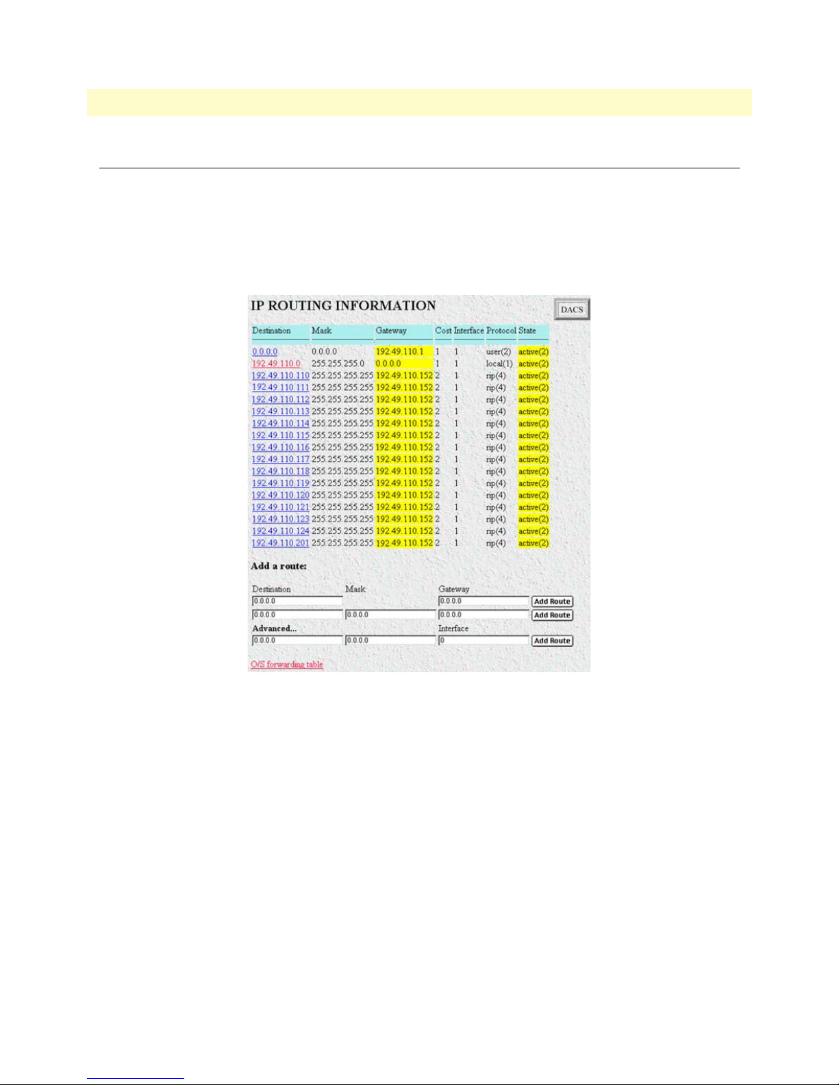
10 • IP T1/E1 DACS Administrators’ Reference Guide
Routing Information
The IP Routing Information window (see figure 24) displays information required to route IP datagrams,
including the IP address, subnet mask, next-hop router, and interface for each network interface defined in the
DACS.
The IP Routing Information window also has a link to the O/S forwarding table where the forwarding parameters are displayed (“O/S forwarding table window” on page 68).
Destination (ipRouteDest)
The destination IP address of this route. An entry with a value of 0.0.0.0 is considered a default route. Multiple
routes to a single destination can appear in the table, but access to such multiple entries is dependent on the
table-access mechanisms defined by the network management protocol in use.
To view or modify next-hop routing information for each destination, click on a destination link in the
nation
column. For more information about modifying next-hop routing information settings, refer to “IP
Routing Destination window” on page 70.
66 Routing Information
Figure 24. IP Routing Information window
Desti-
Page 69

T1/E1 DACS Administrators’ Reference Guide 10 • IP
Mask (ipRouteMask)
Indicates the mask to be logical-ANDed with the destination address before being compared to the value in the
ipRouteDest field. For those systems that do not support arbitrary subnet masks, an agent constructs the value
of the ipRouteMask by determining whether the value of the corresponding ipRouteDest field belongs to a
Class A, B, or C network, and then using the appropriate mask from table 3.
Table 3. Masks
Mask Network
255.0.0.0 class-A
255.255.0.0 class-B
255.255.255.0 class-C
Gateway (RouteGateway)
Specifies the IP address to which the packets should be forwarded.
Cost (RouteCost)
This is the cost of the route as defined by RIP standards. Cost is sometimes considered to be number of hops.
A cost of 16 is considered to be infinite. A cost can be given to user-entered routes so their preference in relation to learned routes can be calculated.
Interface (ipRouteIfIndex)
The index value that identifies the local interface through which the next hop of this route should be reached.
The interface identified by a particular value of this index is the same interface as identified by the same value
of ifIndex.
State (RouteState)
• invalid(1)—This setting deletes the route.
• active(2)—A valid route is in use.
• nopath(3)—No route is available to the specified gateway. The gateway is not known to local networks.
• agedout(4)—Invalid route (soon to be removed).
• costly(5)—A valid route, but not in use because of it’s higher cost.
Add a route:
This portion of the IP Routing Information window is where you can add a new route to the IP Routing Information table. Fill in the
Destination, Mask, and Gateway information, then click Add Route.
Advanced…
Enables a route to be attached to an interface. Packets to a network will be routed to that interface, allowing
the gateway IP address to be dynamic.
Routing Information 67
Page 70
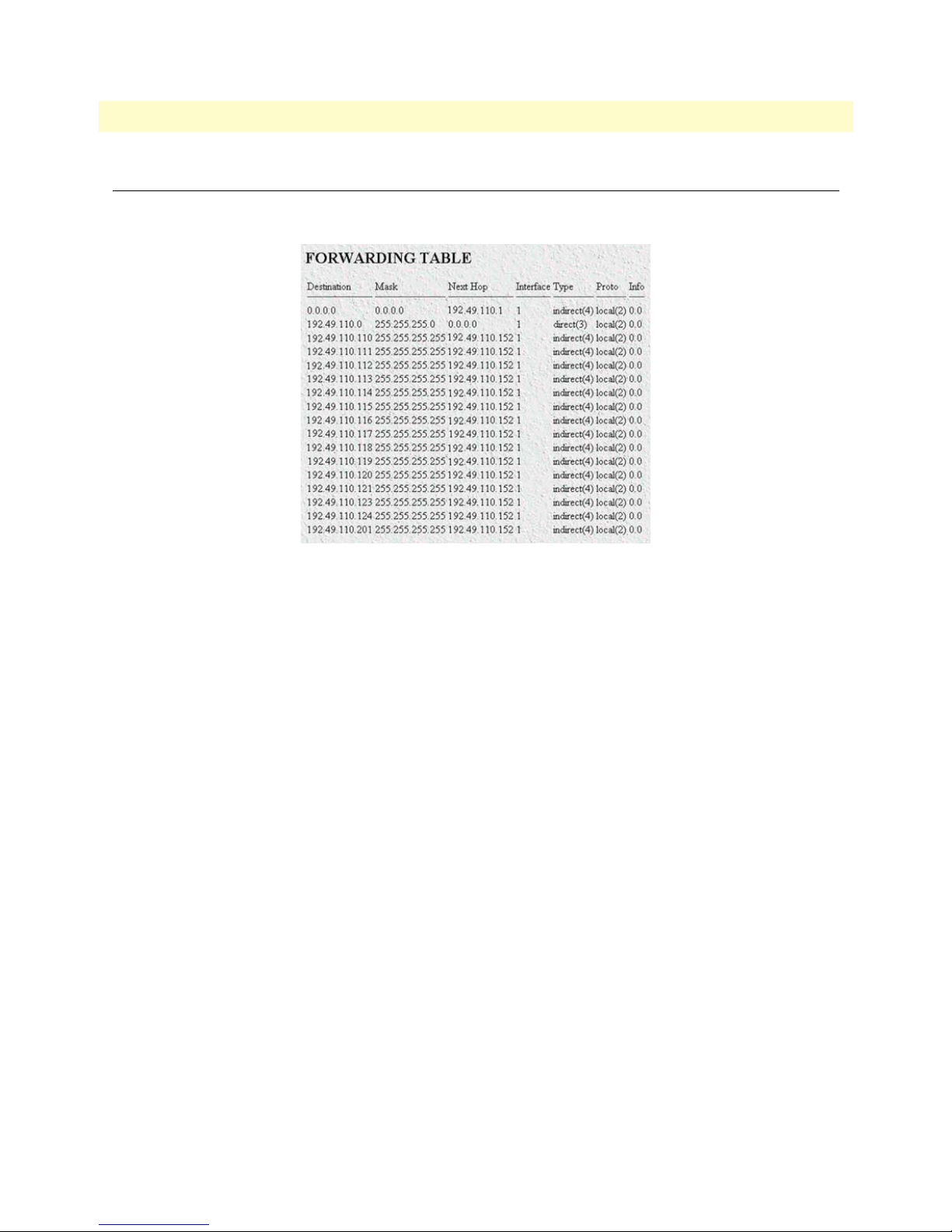
10 • IP T1/E1 DACS Administrators’ Reference Guide
O/S forwarding table window
The O/S forwarding table window lists forwarding information for all routes.
Figure 25. IP Routing Forwarding Table
Destination (ipRouteDest)
The destination IP address of this route. An entry with a value of 0.0.0.0 is considered a default route. Multiple
routes to a single destination can appear in the table, but access to such multiple entries is dependent on the
table-access mechanisms defined by the network management protocol in use.
Mask (ipRouteMask)
Indicates the mask to be logical-ANDed with the destination address before being compared to the value in the
ipRouteDest field. For those systems that do not support arbitrary subnet masks, an agent constructs the value
of the ipRouteMask by determining whether the value of the correspondent ipRouteDest field belongs to a
Class A, B, or C network, and then using the appropriate mask from table 3 on page 67.
Next Hop (ipRouteNextHop)
The IP address of the next hop of this route. (In the case of a route bound to an interface which is realized via
a broadcast media, the value of this field is the agent's IP address on that interface.)
Interface (ipRouteIfIndex)
The index value that identifies the local interface through which the next hop of this route should be reached.
The interface identified by a particular value of this index is the same interface as identified by the same value
of ifIndex.
Type (ipRouteType)
One of the following route types:
• other(1)—none of the following
• invalid(2)—an invalidated route
68 O/S forwarding table window
Page 71

T1/E1 DACS Administrators’ Reference Guide 10 • IP
• direct(3)—route to directly connected (sub-)network
• indirect(4)—route to a non-local host/network/sub-network
Note The values direct(3) and indirect(4) refer to the notion of direct and
indirect routing in the IP architecture. Setting this object to the value
invalid(2) has the effect of invalidating the corresponding entry in the
ipRouteTable object. That is, it effectively disassociates the destination identified with said entry from the route identified with said
entry. It is an implementation-specific matter as to whether the agent
removes an invalidated entry from the table. Accordingly, management stations must be prepared to receive tabular information from
agents that corresponds to entries not currently in use. Proper interpretation of such entries requires examination of the relevant
ipRouteType object.
Protocol (ipRouteProto)
The routing mechanism via which this route was learned. Inclusion of values for gateway routing protocols is
not intended to imply that hosts must support those protocols.
• unknown(0)
• local(1)—Added by the DACS to support an interface. For example, adding a route for a new dial-in user.
• user(2)—Added by an administrator on the IP Routing Information table or via SNMP management tools.
• dspf(3)—Not currently implemented.
• rip(4)—Learned via reception of RIP packet.
• icmp(5)—Learned via reception of ICMP packet.
• radius(6)—Provided in RADIUS response packet.
Info (ipRouteInfo)
A reference to MIB definitions specific to the particular routing protocol which is responsible for this route, as
determined by the value specified in the route’s ipRouteProto value. If this information is not present, its value
should be set to the OBJECT IDENTIFIER { 0 0 }, which is a syntactically valid object identifier, and any
conformant implementation of ASN.1 and BER must be able to generate and recognize this value.
O/S forwarding table window 69
Page 72

10 • IP T1/E1 DACS Administrators’ Reference Guide
IP Routing Destination window
The IP Routing Destination window (see figure 26) shows next-hop routing information.
Figure 26. Routing Destination window
Route Destination (ipRouteDest)
The destination IP address of this route. An entry with a value of 0.0.0.0 is considered a default route. Multiple
routes to a single destination can appear in the table, but access to such multiple entries is dependent on the
table-access mechanisms defined by the network management protocol in use.
Mask (ipRouteMask)
Indicates the mask to be logical-ANDed with the destination address before being compared to the value in the
ipRouteDest field. For those systems that do not support arbitrary subnet masks, an agent constructs the value
of the ipRouteMask by determining whether the value of the corresponding ipRouteDest field belongs to a
Class A, B, or C network, and then using the appropriate mask from table 3 on page 67.
Interface (ipRouteIfIndex)
The index value which uniquely identifies the local interface through which the next hop of this route should
be reached. The interface identified by a particular value of this index is the same interface as identified by the
same value of ifIndex.
Protocol (ipRouteProto)
The routing mechanism via which this route was learned. Inclusion of values for gateway routing protocols is
not intended to imply that hosts must support those protocols.
• unknown(0)
• local(1)—Added by the DACS to support an interface. For example, adding a route for a new dial-in user.
• user(2)—Added by an administrator on the IP Routing Information table or via SNMP management tools.
• dspf(3)—Not currently implemented.
• rip(4)—Learned via reception of RIP packet.
• icmp(5)—Learned via reception of ICMP packet.
• radius(6)—Provided in RADIUS response packet.
70 IP Routing Destination window
Page 73

T1/E1 DACS Administrators’ Reference Guide 10 • IP
Seconds Since Updated (ipRouteAge)
The number of seconds since this route was last updated or otherwise determined to be correct.
Tag (RouteTag)
An identifier associated with the route. This can have different meanings depending on the protocol. For example, this gives the tag that was passed with a learned RIP route.
Gateway (RouteGateway)
Specifies the IP address to which the packets should be forwarded.
Cost (RouteCost)
This is the cost of the route as defined by RIP standards. Cost is sometimes considered to be number of hops.
A cost of 16 is considered to be infinite. A cost can be given to user-entered routes so their preference in relation to learned routes can be calculated.
State (RouteState)
Defines the state which a route may be in during its lifetime.
• invalid(1)—This setting deletes the route.
• active(2)—A valid route is in use.
• nopath(3)—No route is available to the specified gateway. The gateway is not known to local networks.
• agedout(4)—Invalid route (soon to be removed).
• costly(5)—A valid route, but not in use because of it’s higher cost.
Address Translation Information
The IP address translation table window (see figure 27) contain the IP address to physical address equivalences.
Some interfaces do not use translation tables for determining address equivalences (for example, DDN-X.25
uses an algorithmic method)—if all interfaces are of this type, then the Address Translation table is empty (zero
entries).
Figure 27. Address Translation Information window
Interface (ipNetToMediaEntry)
Each entry contains one IP address to physical address equivalence.
Address Translation Information 71
Page 74

10 • IP T1/E1 DACS Administrators’ Reference Guide
Net Address (ipNetToMediaNetAddress)
The IP address corresponding to the media-dependent physical address.
Physical (ipNetToMediaPhysAddress)
The media-dependent physical address.
Type (ipNetToMediaType)
The type of mapping. Setting this object to the value invalid(2) has the effect of invalidating the corresponding
entry in the ipNetToMediaTable. That is, it effectively disassociates the interface identified with said entry
from the mapping identified with said entry. It is an implementation-specific matter as to whether the agent
removes an invalidated entry from the table. Accordingly, management stations must be prepared to receive
tabular information from agents that corresponds to entries not currently in use. Proper interpretation of such
entries requires examination of the relevant ipNetToMediaType object.
• other(1)—none of the following
• invalid(2)—an invalidated mapping
• dynamic(3)
• static(4)
72 Address Translation Information
Page 75

Chapter 11 TCP
Chapter contents
Introduction..........................................................................................................................................................74
TCP main window ................................................................................................................................................74
Retransmit-Timeout Algorithm (tcpRtoAlgorithm) ........................................................................................74
Retransmit-Timeout Minimum (tcpRtoMin) .................................................................................................74
Retransmit-Timeout Maximum (tcpRtoMax) .................................................................................................74
Maximum Connections (tcpMaxConn) ..........................................................................................................75
Active Opens (tcpActiveOpens) ......................................................................................................................75
Passive Opens (tcpPassiveOpens) ....................................................................................................................75
Attempt/Fails (tcpAttemptFails) ......................................................................................................................75
ESTABLISHED Resets (tcpEstabResets) ........................................................................................................75
Current ESTABLISHED (tcpCurrEstab) .......................................................................................................75
Total Received (tcpInSegs) ..............................................................................................................................75
Total Sent (tcpOutSegs) ..................................................................................................................................75
Total Retransmitted (tcpRetransSegs) .............................................................................................................75
Total Received in Error (tcpInErrs) .................................................................................................................75
Total Sent w/RST Flag (tcpOutRsts) ..............................................................................................................75
TCP (Details)........................................................................................................................................................76
Local Port (tcpConnLocalPort) .......................................................................................................................76
Remote Address (tcpConnRemAddress) .........................................................................................................76
Remote Port (tcpConnRemPort) ....................................................................................................................76
State (tcpConnState) .......................................................................................................................................76
73
Page 76
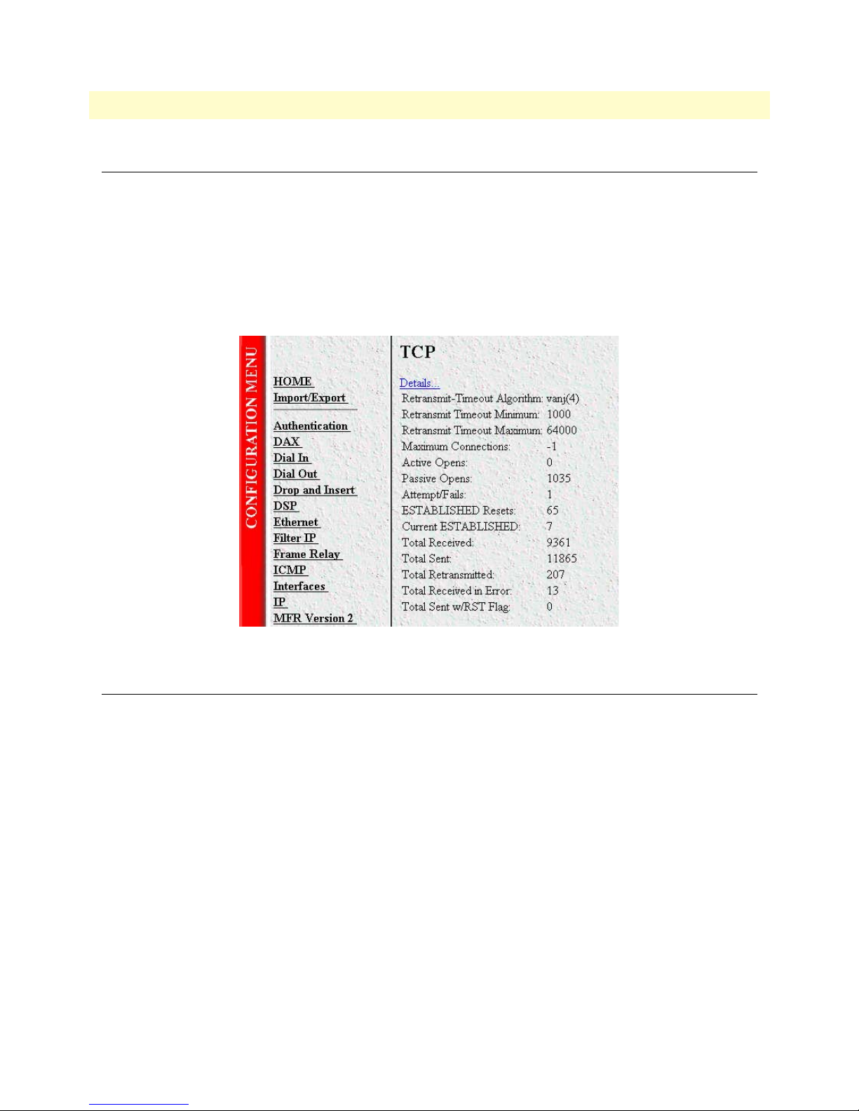
11 • TCP T1/E1 DACS Administrators’ Reference Guide
Introduction
Transmission Control Protocol (TCP) is in the Transport layer of the OSI model and sits on top of IP. It is one
of the more widely used protocols among the TCP/IP suite. The TCP subsystem web pages of the 2604
DACS provides management and statistical information on TCP. Detailed information regarding the SNMP
MIB variables may be downloaded from RFC1213: Management Information Base for Network Management
of TCP/IP-based internets: MIB-II.
Click on
TCP under the Configuration Menu to display the TCP main window (see figure 28) to monitor TCP
statistics.
TCP main window
Figure 28. TCP main window
Retransmit-Timeout Algorithm (tcpRtoAlgorithm)
The algorithm that determines the timeout value used for retransmitting unacknowledged octets.
Retransmit-Timeout Minimum (tcpRtoMin)
The minimum value permitted by a TCP implementation for the retransmission timeout, measured in milliseconds. More refined semantics for objects of this type depend upon the algorithm used to determine the
retransmission timeout. In particular, when the timeout algorithm is rsre(3), an object of this type has the
semantics of the LBOUND quantity described in RFC 793.
Retransmit-Timeout Maximum (tcpRtoMax)
The maximum value permitted by a TCP implementation for the retransmission timeout, measured in milliseconds. More refined semantics for objects of this type depend upon the algorithm used to determine the
retransmission timeout. In particular, when the timeout algorithm is rsre(3), an object of this type has the
semantics of the UBOUND quantity described in RFC 793.
74 Introduction
Page 77

T1/E1 DACS Administrators’ Reference Guide 11 • TCP
Maximum Connections (tcpMaxConn)
The limit on the total number of TCP connections the entity can support. In entities where the maximum
number of connections is dynamic, this object should contain the value -1.
Active Opens (tcpActiveOpens)
The number of times TCP connections have made a direct transition to the SYN-SENT state from the
CLOSED state.
Passive Opens (tcpPassiveOpens)
The number of times TCP connections have made a direct transition to the SYN-RCVD state from the LISTEN state.
Attempt/Fails (tcpAttemptFails)
The number of times TCP connections have made a direct transition to the CLOSED state from either the
SYN-SENT state or the SYN-RCVD state, plus the number of times TCP connections have made a direct
transition to the LISTEN state from the SYN-RCVD state.
ESTABLISHED Resets (tcpEstabResets)
The number of times TCP connections have made a direct transition to the CLOSED state from either the
ESTABLISHED state or the CLOSE-WAIT state.
Current ESTABLISHED (tcpCurrEstab)
The number of TCP connections for which the current state is either ESTABLISHED or CLOSE-WAIT.
Total Received (tcpInSegs)
The total number of segments received, including those received in error. This count includes segments
received on currently established connections.
Total Sent (tcpOutSegs)
The total number of segments sent, including those on current connections but excluding those containing
only retransmitted octets.
Total Retransmitted (tcpRetransSegs)
The total number of segments retransmitted—that is, the number of TCP segments transmitted containing
one or more previously transmitted octets.
Total Received in Error (tcpInErrs)
The total number of segments received in error (e.g., bad TCP checksums).
Total Sent w/RST Flag (tcpOutRsts)
The number of TCP segments sent containing the RST flag.
TCP main window 75
Page 78

11 • TCP T1/E1 DACS Administrators’ Reference Guide
TCP (Details)
From this screen you can view port details for remote and local TCP connections (see figure 29).
Figure 29. TCP Details window
Local Port (tcpConnLocalPort)
The local port number for this TCP connection.
Remote Address (tcpConnRemAddress)
The remote IP address for this TCP connection.
Remote Port (tcpConnRemPort)
The remote port number for this TCP connection.
State (tcpConnState)
The state of this TCP connection. The only value which may be set by a management station is deleteTCB(12). Accordingly, it is appropriate for an agent to return a ‘badValue’ response if a management station
attempts to set this object to any other value.
If a management station sets this object to the value deleteTCB(12), Transmission Control Block, then this has
the effect of deleting the TCB (as defined in RFC 793) of the corresponding connection on the managed node,
resulting in immediate termination of the connection. As an implementation-specific option, a RST segment
may be sent from the managed node to the other TCP endpoint (note however that RST segments are not sent
reliably).
• closed(1)
• listen(2)
• synSent(3)
• synReceived(4)
• established(5)
76 TCP (Details)
Page 79

T1/E1 DACS Administrators’ Reference Guide 11 • TCP
• finWait1(6)
• finWait2(7)
• closeWait(8)
• lastAck(9)
• closing(10)
• timeWait(11)
• deleteTCB(12)
TCP (Details) 77
Page 80

11 • TCP T1/E1 DACS Administrators’ Reference Guide
78 TCP (Details)
Page 81

Chapter 12 UDP
Chapter contents
Introduction..........................................................................................................................................................80
Handling of NETBIOS UDP Broadcasts (boxNetbiosUdpBridging) ..............................................................80
Received (udpInDatagrams) ............................................................................................................................80
Received With No Ports (udpNoPorts) ...........................................................................................................80
Others Received with No Delivery (udpInErrors) ...........................................................................................80
Sent (udpOutDatagrams) ................................................................................................................................80
Listener Table (udpTable) ...............................................................................................................................81
Local Address (udpLocalAddress) ....................................................................................................................81
Local Port (udpLocalPort) ...............................................................................................................................81
79
Page 82
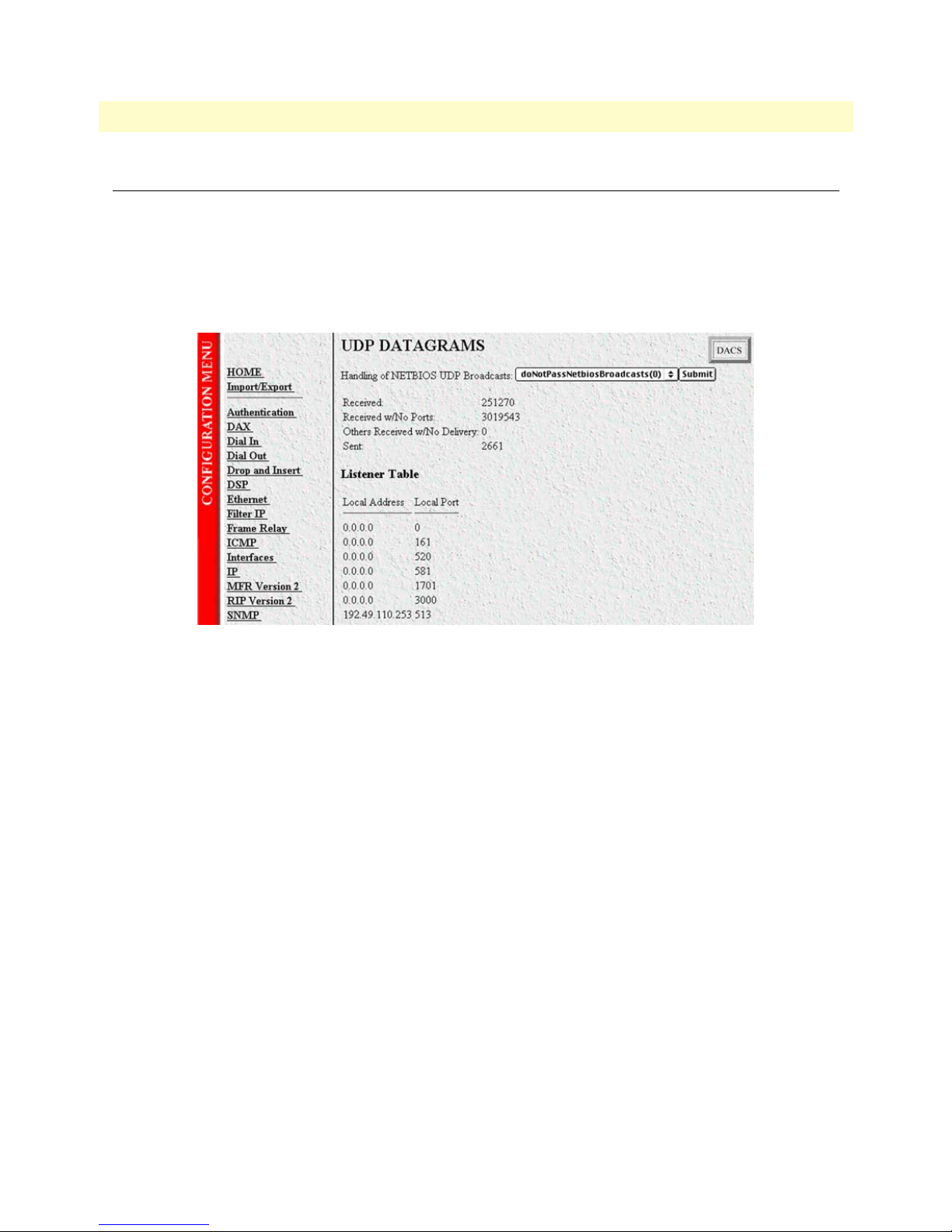
12 • UDP T1/E1 DACS Administrators’ Reference Guide
Introduction
User Datagram Protocol (UDP) is supported by the DACS. Detailed information regarding the SNMP management information base (MIB) variables can be found in RFC1213: Management Information Base for
Network Management of TCP/IP-based internets: MIB-II.
To manage and collect statistics on UDP, click on
UDP under the Configuration Menu to display the UDP win-
dow (see figure 30).
Figure 30. UDP window
Handling of NETBIOS UDP Broadcasts (boxNetbiosUdpBridging)
Enables the passing of broadcast UDP packets with a port of 137 and 138 from other interfaces to the local
LAN interface. Netbios uses these packets to communicate with WINS servers. A WINS server can work without this option enabled, but the remote PC will appear to be on the LAN. The following options are available:
• doNotPassNetbiosBroadcasts(0)
• passNetbiosBroadcasts(1)
Received (udpInDatagrams)
The total number of UDP datagrams delivered to UDP users.
Received With No Ports (udpNoPorts)
The total number of received UDP datagrams for which there was no application at the destination port.
Others Received with No Delivery (udpInErrors)
The number of received UDP datagrams that could not be delivered for reasons other than the lack of an
application at the destination port.
Sent (udpOutDatagrams)
The total number of UDP datagrams sent from this entity.
80 Introduction
Page 83

T1/E1 DACS Administrators’ Reference Guide 12 • UDP
Listener Table (udpTable)
A table containing UDP listener information.
Local Address (udpLocalAddress)
The local IP address for this UDP listener. In the case of a UDP listener that is willing to accept datagrams for
any IP interface associated with the node, the value 0.0.0.0 is used.
Local Port (udpLocalPort)
The local port number for this UDP listener.
Introduction 81
Page 84

12 • UDP T1/E1 DACS Administrators’ Reference Guide
82 Introduction
Page 85

Chapter 13 RIP Version 2
Chapter contents
Introduction..........................................................................................................................................................84
RIP Version 2 main window..................................................................................................................................84
Route Changes Made (rip2GlobalRouteChanges) ...........................................................................................84
Responses Sent (rip2GlobalQueries) ...............................................................................................................84
Adding a RIP address ......................................................................................................................................84
RIP Version 2—Configuration..............................................................................................................................85
Address (rip2IfConfAddress) ...........................................................................................................................85
Domain (rip2IfConfDomain) .........................................................................................................................86
Authentication Type (rip2IfConfAuthType) ...................................................................................................86
Authentication Key (rip2IfConfAuthKey) .......................................................................................................86
Send (rip2IfConfSend) ....................................................................................................................................86
Receive (rip2IfConfReceive) ...........................................................................................................................86
Metric (rip2IfConfDefaultMetric) ..................................................................................................................86
Status (rip2IfConfStatus) ................................................................................................................................87
RIP Version 2 (Statistics).......................................................................................................................................87
Subnet IP Address (rip2IfStatAddress) ............................................................................................................87
Bad Packets (rip2IfStatRcvBadPackets) ...........................................................................................................87
Bad Routes (rip2IfStatRcvBadRoutes) ............................................................................................................87
Sent Updates (rip2IfStatSentUpdates) .............................................................................................................87
Status (rip2IfStatStatus) ..................................................................................................................................87
83
Page 86

13 • RIP Version 2 T1/E1 DACS Administrators’ Reference Guide
Introduction
The RIP Version 2 main window (see figure 31) describes routing information as defined by the Routing Infor-
mation Protocol (RIP). All object identifiers described in this chapter comply with those contained in RFC
1724: RIP Version 2 MIB Extension.
Figure 31. RIP Version 2 window
Click on RIP Version 2 under the Configuration Menu to display the RIP Version 2 main window.
RIP Version 2 main window
The RIP Version 2 window describes routing information as defined by the Routing Information Protocol
(RIP). The window also contains the following links:
Statistics—Clicking on the Statistics link displays the RIP Version 2 Status window (see “RIP Version 2
•
(Statistics)” on page 87). In this window you can view each subnet IP address, Bad Packets, Bad Routes,
Sent Updates, and Status.
•
Address (xxx.xxx.xxx.xxx)— After adding a RIP address, click on the IP Address under the Address column
to display the
sion 2 (Statistics)” on page 87).
Route Changes Made (rip2GlobalRouteChanges)
The number of route changes made to the IP Route Database by RIP. This does not include the refresh of a
route's age.
Responses Sent (rip2GlobalQueries)
The number of responses sent to RIP queries from other systems.
Adding a RIP address
Do the following:
RIP Version 2 Configuration window. You can modify the configuration here. (see “RIP Ver-
1. Enter the IP network address of the interface on the 2604 DACS that you want to enable RIP. This will
be the LAN IP address, in other words, the IP address of the 2604. This is not the IP address of the device
you want to direct RIP packets to.
84 Introduction
Page 87

T1/E1 DACS Administrators’ Reference Guide 13 • RIP Version 2
2. Enter the protocol version to be used for sending RIP packets. The following choices are available:
– doNotSend (1)
– ripVersion1 (2)—ripVersion 1 implies sending RIP updates compliant with RFC 1058
rip1Compatible (3)—rip1Compatible implies broadcasting RIP-2 updates using RFC 1058 route sub-
–
sumption rules
ripVersion2 (4)—ripVersion2 implies multicasting RIP-2 updates
–
3. Enter the protocol version to be used for receiving RIP packets. The following choices are available (note
that rip2 and rip1OrRip2 implies reception of multicast packets.):
rip1 (1)—ripVersion 1 implies sending RIP updates compliant with RFC 1058
–
rip2(2)—rip1Compatible implies broadcasting RIP-2 updates using RFC 1058 route subsumption rules
–
– rip1OrRip2(3)
– doNotReceive(4)
4. Click on Submit Query.
Note To delete the RIP Address, click on the IP Address under the column
named
Submit Query.
Address. Select Status to be invalid(2) and click on
Further modifications can be made by clicking on the
Address link of the specific subnet (see “RIP Version
2—Configuration”).
RIP Version 2—Configuration
The RIP Version 2 Configuration window (see figure 32), seen by clicking on the IP Address under the column
named
ters are
Address (rip2IfConfAddress)
The IP Address of this system on the indicated subnet. For unnumbered interfaces, the value 0.0.0.N, where
the least significant 24 bits (N) is the ifIndex for the IP Interface in network byte order.
Address, displays the RIP IP Address followed by configurable parameters. The configurable parame-
Domain, Authentication Type, Authentication Key, Send, Receive, Metric, and Status.
Figure 32. RIP Version 2—Statistics Configuration window
RIP Version 2—Configuration 85
Page 88

13 • RIP Version 2 T1/E1 DACS Administrators’ Reference Guide
Domain (rip2IfConfDomain)
Value inserted into the Routing Domain field of all RIP packets sent on this interface.
Authentication Type (rip2IfConfAuthType)
The type of Authentication used on this interface.
• noAuthentication (1)
• simplePassword (2)
Authentication Key (rip2IfConfAuthKey)
This value is used as the Authentication Key whenever Authentication Type (rip2IfConfAuthType) has a value
other than noAuthentication(1). A modification of
cation Key
. If the Authentication Key string is shorter than 16 octets, it will be left justified, then padded to 16
Authentication Type does not change the value of Authenti-
octets with nulls (0x00) on the right.
Reading this object always results in an octet string of length zero. Authentication may not be bypassed by
reading the MIB object.
Send (rip2IfConfSend)
Send is what the router sends on this interface. ripVersion 1 implies sending RIP updates compliant with RFC
1058. There are four options,
doNotSend(1), ripVersion1(2), rip1Compatible(3), and ripVersion2(4).
rip1Compatible implies broadcasting RIP-2 updates using RFC 1058 route subsumption rules. ripVersion2
implies multicasting RIP-2 updates. ripV1Demand indicates the use of Demand RIP on a WAN interface
under RIP Version 1 rules. ripV2Demand indicates the use of Demand RIP on a WAN interface under Version
2 rules.
• doNotSend (1)
• ripVersion1 (2)
• rip1Compatible (3)—rip1Compatible implies broadcasting RIP-2 updates using RFC 1058 route sub-
sumption rules
• ripVersion2 (4)—ripVersion2 implies multicasting RIP-2 updates
Receive (rip2IfConfReceive)
This indicates which version of RIP updates are to be accepted. Note that rip2 and rip1OrRip2 implies reception of multicast packets.
• rip1 (1)
• rip2 (2)
• rip1OrRip2 (3)
• doNotRecieve (4)
Metric (rip2IfConfDefaultMetric)
This variable indicates the metric that is to be used for the default route entry in RIP updates originated on this
interface. A value of zero indicates that no default route should be originated; in this case, a default route via
another router may be propagated.
86 RIP Version 2—Configuration
Page 89
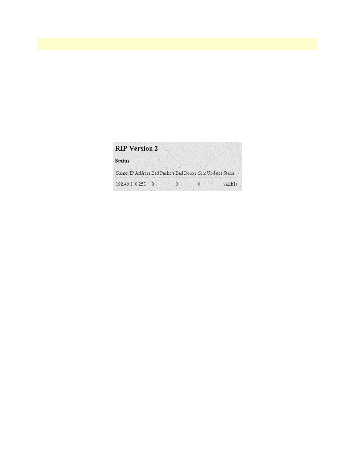
T1/E1 DACS Administrators’ Reference Guide 13 • RIP Version 2
Status (rip2IfConfStatus)
Writing invalid has the effect of deleting this interface.
• valid (1)
• invalid (2)
RIP Version 2 (Statistics)
By clicking on Statistics in the RIP Version 2 main window, you enter the RIP Version 2 Status win-
dow (see figure 33)It displays routing and update information for each subnet address.
Figure 33. RIP Version 2 details window
Subnet IP Address (rip2IfStatAddress)
The IP Address of this system on the indicated subnet. For unnumbered interfaces, the value 0.0.0.N, where
the least significant 24 bits (N) is the ifIndex for the IP Interface in network byte order.
Bad Packets (rip2IfStatRcvBadPackets)
The number of RIP response packets received by the RIP process which were subsequently discarded for any
reason (e.g. a version 0 packet, or an unknown command type).
Bad Routes (rip2IfStatRcvBadRoutes)
The number of routes, in valid RIP packets, which were ignored for any reason (e.g. unknown address family,
or invalid metric).
Sent Updates (rip2IfStatSentUpdates)
The number of triggered RIP updates actually sent on this interface. This explicitly does NOT include full
updates sent containing new information.
Status (rip2IfStatStatus)
Displays whether the Subnet IP Address is valid or invalid.
RIP Version 2 (Statistics) 87
Page 90

13 • RIP Version 2 T1/E1 DACS Administrators’ Reference Guide
88 RIP Version 2 (Statistics)
Page 91

Chapter 14 SNMP
Chapter contents
Introduction..........................................................................................................................................................90
SNMP window......................................................................................................................................................90
In ..........................................................................................................................................................................90
Packets (snmpInPkts) ......................................................................................................................................90
Bad Version (snmpInBadVersions) .................................................................................................................90
Bad Community Names (snmpInBadCommunityNames) ..............................................................................91
Bad Community Uses (snmpInBadCommunity) ............................................................................................91
ASN ParseErrors (snmpInASNParseErrs) ........................................................................................................91
Error Status “Too Big” (snmpInTooBigs) .......................................................................................................91
No Such Names (snmpInNoSuchNames) .......................................................................................................91
Bad Values (snmpInBadValues) ......................................................................................................................91
Error Status “Read Only” (snmpInReadOnlys) ...............................................................................................91
Generated Errors (snmpInGenErrs) ................................................................................................................91
Get/Get Next Variables (snmpInTotalReqVars) .............................................................................................91
Set Variables (snmpInTotalSetVars) ................................................................................................................91
Get Requests (snmpInGetRequests) ................................................................................................................91
Get Next Requests (snmpInGetNexts) ............................................................................................................92
Set Requests (snmpInSetRequests) ..................................................................................................................92
Get Responses (snmpInGetResponses) ............................................................................................................92
Traps (snmpInTraps) ......................................................................................................................................92
Out .......................................................................................................................................................................92
Out Packets (snmpOutPkts) ...........................................................................................................................92
Error Status “Too Big” (snmpOutTooBigs) ....................................................................................................92
No Such Names (snmpOutNoSuchNames) ....................................................................................................92
Bad Values (snmpOutBadValues) ...................................................................................................................92
Generated Errors (snmpOutGenErrs) .............................................................................................................92
Get Requests (snmpOutGetRequests) .............................................................................................................92
Get Next Requests (snmpOutGetNexts) .........................................................................................................92
Set Requests (snmpOutSetRequests) ...............................................................................................................92
Get Responses (snmpOutGetResponses) .........................................................................................................93
Traps (snmpOutTraps) ...................................................................................................................................93
Authentication Failure Traps (snmpEnableAuthenTraps) ...............................................................................93
89
Page 92
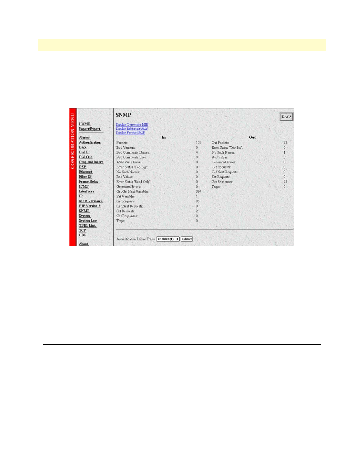
14 • SNMP T1/E1 DACS Administrators’ Reference Guide
Introduction
The DACS provides management and statistical information on SNMP. Detailed information on the SNMP
MIB variables may be downloaded from the RFC. Click on
play the SNMP window (see figure 34).
SNMP under the Configuration Menu to dis-
Figure 34. SNMP window
SNMP window
The SNMP window displays incoming and outgoing SNMP statistics, and has links for downloading and displaying the following MIB documents:
• Corporate MIB
• Enterprise MIB
• Product MIB
In
Packets (snmpInPkts)
The total number of Messages delivered to the SNMP entity from the transport service. Typically this would be
UDP since the SNMP engine sits on top of UDP
Bad Version (snmpInBadVersions)
The total number of SNMP Messages that were delivered to the SNMP protocol entity and were for an unsupported SNMP version.
90 Introduction
Page 93

T1/E1 DACS Administrators’ Reference Guide 14 • SNMP
Bad Community Names (snmpInBadCommunityNames)
The total number of SNMP Messages delivered to the SNMP protocol entity which used a SNMP community
name not known to said entity.
Bad Community Uses (snmpInBadCommunity)
The total number of SNMP messages delivered to the SNMP protocol entity which represented an SNMP
operation which was not allowed by the SNMP community named in the message.
ASN ParseErrors (snmpInASNParseErrs)
The total number of ASN.1 or BER errors encountered by the SNMP protocol entity when decoding received
SNMP messages.
Error Status “Too Big” (snmpInTooBigs)
The total number of SNMP PDUs that were delivered to the SNMP protocol entity and for which the value of
the error-status field is tooBig.
No Such Names (snmpInNoSuchNames)
The total number of SNMP PDUs that were delivered to the SNMP protocol entity and for which the value of
the error-status field is noSuchName.
Bad Values (snmpInBadValues)
The total number of SNMP PDUs that were delivered to the SNMP protocol entity and for which the value of
the error-status field is badValue.
Error Status “Read Only” (snmpInReadOnlys)
The total number of valid SNMP PDUs that were delivered to the SNMP protocol entity and for which the
value of the error-status field is readOnly. It should be noted that it is a protocol error to generate an SNMP
PDU which contains the readOnly value in the error-status field, as such this object is provided as a means of
detecting incorrect implementations of the SNMP.
Generated Errors (snmpInGenErrs)
The total number of SNMP PDUs that were delivered to the SNMP protocol entity and for which the value of
the error-status field is genErr.
Get/Get Next Variables (snmpInTotalReqVars)
The total number of MIB objects that have been retrieved successfully by the SNMP protocol entity as the
result of receiving valid SNMP Get-Request and Get-Next PDUs.
Set Variables (snmpInTotalSetVars)
The total number of MIB objects that have been altered successfully by the SNMP protocol entity as the result
of receiving valid SNMP Set-Request PDUs.
Get Requests (snmpInGetRequests)
The total number of SNMP Get-Request PDUs that have been accepted and processed by the SNMP protocol
entity.
In 91
Page 94

14 • SNMP T1/E1 DACS Administrators’ Reference Guide
Get Next Requests (snmpInGetNexts)
The total number of SNMP Get-Next PDUs that have been accepted and processed by the SNMP protocol
entity.
Set Requests (snmpInSetRequests)
The total number of SNMP Set-Request PDUs that have been accepted and processed by the SNMP protocol
entity.
Get Responses (snmpInGetResponses)
The total number of SNMP Get-Response PDUs that have been accepted and processed by the SNMP protocol entity.
Traps (snmpInTraps)
The total number of SNMP Trap PDUs that have been accepted and processed by the SNMP protocol entity.
Out
Out Packets (snmpOutPkts)
The total number of SNMP messages that were passed from the SNMP protocol entity to the transport service.
Error Status “Too Big” (snmpOutTooBigs)
The total number of SNMP PDUs that were generated by the SNMP protocol entity and for which the value
of the error-status field is tooBig.
No Such Names (snmpOutNoSuchNames)
The total number of SNMP PDUs that were generated by the SNMP protocol entity and for which the value
of the error-status is noSuchName.
Bad Values (snmpOutBadValues)
The total number of SNMP PDUs that were generated by the SNMP protocol entity and for which the value
of the error-status field is badValue.
Generated Errors (snmpOutGenErrs)
The total number of SNMP PDUs that were generated by the SNMP protocol entity and for which the value
of the error-status field is genErr.
Get Requests (snmpOutGetRequests)
The total number of SNMP Get-Request PDUs that have been generated by the SNMP protocol entity.
Get Next Requests (snmpOutGetNexts)
The total number of SNMP Get-Next PDUs that have been generated by the SNMP protocol entity.
Set Requests (snmpOutSetRequests)
The total number of SNMP Set-Request PDUs that have been generated by the SNMP protocol entity.
92 Out
Page 95

T1/E1 DACS Administrators’ Reference Guide 14 • SNMP
Get Responses (snmpOutGetResponses)
The total number of SNMP Get-Response PDUs that have been generated by the SNMP protocol entity.
Traps (snmpOutTraps)
The total number of SNMP Trap PDUs that have been generated by the SNMP protocol entity.
Authentication Failure Traps (snmpEnableAuthenTraps)
This value indicates whether the SNMP agent process is permitted to generate authentication-failure traps.
The variable is global. This means that by being disabled, all authentication-failure traps are disabled.
Note Note: It is strongly recommended that upon selecting either
enabled(1) or disabled(2), it be saved in non-volatile memory by clicking on Record Current Configuration under
Immediate Actions
on the Home page of the 2604 DACS. If the network management
system is re-initialized (implying power cycling) while assuming the
current configuration has been recorded, the current configuration
will not be lost.
The two options for this variable are:
• enabled(1)
• disabled(2)
Out 93
Page 96

14 • SNMP T1/E1 DACS Administrators’ Reference Guide
94 Out
Page 97

Chapter 15 System
Chapter contents
Introduction..........................................................................................................................................................97
System main window.............................................................................................................................................98
CPU ...............................................................................................................................................................98
Percentage CPU Idle (boxidletime) ...........................................................................................................98
Time Slices Fully Utilized (boxCPUcritical) ..............................................................................................98
Time Slices 90% Utilized (boxCPUWarning) ...........................................................................................98
SNMP and HTTP ..........................................................................................................................................98
Version (boxSnmpVersion) .......................................................................................................................98
Super User Password (boxSnmpMasterPassword) ......................................................................................98
User Password (boxSnmpMonitorPassword) .............................................................................................98
LAN IP ...........................................................................................................................................................98
How to Obtain Address (boxIPAddressTechnique) ...................................................................................99
Address(boxIPAddress) ..............................................................................................................................99
Mask(boxIPMask) .....................................................................................................................................99
Manufacturer ..................................................................................................................................................99
Serial Number (boxManufactureDatecode) ...............................................................................................99
PCB Revision (boxManufacturePcbRevision) ............................................................................................99
General Information (boxManufactureGeneralInfo) .................................................................................99
Message Blocks ...............................................................................................................................................99
Packet Holding Message Blocks... .............................................................................................................99
Total (boxMsgBlksConfigured) .................................................................................................................99
Free (boxMsgBlksFree) ..............................................................................................................................99
Total Time Waited (boxCountMsgBlkTaskWait) .....................................................................................99
Total Times Unavailable (boxCountMsgBlkUnavailable) ........................................................................100
Operating System Heap Memory ..................................................................................................................100
Total Size (boxHeapSize) ........................................................................................................................100
Free (boxHeapFreeSpace) ........................................................................................................................100
Largest (boxHeapLargestSpace) ...............................................................................................................100
Enclosure System ..........................................................................................................................................100
Internal Temperature (boxTemperature) .................................................................................................100
Highest Temperature (boxMaxTemperature) ..........................................................................................100
Installation ....................................................................................................................................................100
Country (installCountry) ........................................................................................................................100
Other ............................................................................................................................................................100
Total DRAM Detected (boxDetectedMemory) .......................................................................................100
SystemID (sysObjectID) .........................................................................................................................100
Running Since Last Boot (sysUpTime) ...................................................................................................101
System Manager (sysContact) ..................................................................................................................101
Box Name (sysName) ..............................................................................................................................101
95
Page 98

15 • System T1/E1 DACS Administrators’ Reference Guide
Physical Location (sysLocation) ...............................................................................................................101
Web Settings (boxBackgroundFlag) ........................................................................................................101
Monitor Privilege (boxMonitorPrivilege) ................................................................................................101
System—Modify window....................................................................................................................................102
SNMP and HTTP ........................................................................................................................................102
Version (boxSnmpVersion) .....................................................................................................................102
Super User Password (boxSnmpMasterPassword) ....................................................................................102
User Password (boxSnmpMonitorPassword) ...........................................................................................103
LAN IP .........................................................................................................................................................103
Method to Obtain Address (boxIPAddressTechnique) ............................................................................103
Address (boxIPAddress) ...........................................................................................................................103
Mask (boxIPMask) ..................................................................................................................................103
Installation ....................................................................................................................................................103
Country (installCountry) ........................................................................................................................103
Other ............................................................................................................................................................104
System Manager (sysContact) ..................................................................................................................104
Box Name (sysName) ..............................................................................................................................104
Physical Location (sysLocation) ...............................................................................................................104
Web Settings (boxBackgroundFlag) ........................................................................................................104
Monitor Privilege (boxMonitorPrivilege) ................................................................................................104
System—Packet Holding Message Blocks............................................................................................................105
Buffer Size (boxbuffersize) .............................................................................................................................105
No. of Buffers (boxbuffercount) ....................................................................................................................105
No. Free (boxbuffersfree) ..............................................................................................................................105
No. of Tasks Waited (boxCountBufferTaskWait) .........................................................................................105
No. of Times Unavailable(boxCountBufferUnavailable) ...............................................................................105
96
Page 99

T1/E1 DACS Administrators’ Reference Guide 15 • System
Introduction
The System main window (see figure 35) contains general setup information about the DACS. System parameters are Patton Enterprise MIB object identifiers, though some are contained in RFC 1213, Management
Information Base for Network Management of TCP/IP-based internets: MIB-II. Click on
figuration Menu to display the System main window.
System under the Con-
(CPU, SNMP and HTTP, LAN IP, Manufacturer, and Message Blocks)
Introduction 97
Figure 35. System main window
Page 100

15 • System T1/E1 DACS Administrators’ Reference Guide
System main window
From this window you can view information for the CPU, SNMP and HTTP, LAN IP, Manufacturer, Message Blocks, Operating System Heap Memory, Enclosure System, Installation, and Other.
The main window also has the following links:
Modify—click on this link to change SNMP and HTTP, LAN IP, Installation, and Other (see “System—
•
Modify window” on page 102)
Packet Holding Message Blocks—click on this link to view message block statistics (see “System—Packet
•
Holding Message Blocks...” on page 105)
CPU
This portion of the System main window contains information described in the following sections.
Percentage CPU Idle (boxidletime)
This indicates what percentage of the i960 CPU processing power is not being utilized (see figure 35 on
page 97).
Time Slices Fully Utilized (boxCPUcritical)
This value represents a count of how many times the CPU was fully utilized expressed in 1/100th seconds (see
figure 35 on page 97).
Time Slices 90% Utilized (boxCPUWarning)
This value represents a count of how many times the CPU approached full utilization expressed in 1/100th seconds (see figure 35 on page 97).
SNMP and HTTP
This portion of the System main window provides information about the SNMP version and the HTTP accessibility.
Version (boxSnmpVersion)
This parameter indicates the SNMP version number supported by this unit (for example snmpv1(1) means
SNMP version 1 is supported). Select
snmpv1(1) only since SNMP2 is not currently supported.
Super User Password (boxSnmpMasterPassword)
This is the super user password for complete access and configurability of the DACS through SNMP and
HTTP (see figure 35 on page 97).
User Password (boxSnmpMonitorPassword)
This displays the user monitoring password for read only access of certain selected information. Not all parameters shown using the superuser password are displayed under the user password. (see figure 35 on page 97).
LAN IP
This portion of the System main window contains information described in the following sections.
98 System main window
 Loading...