

Page 1
USER
MANUAL
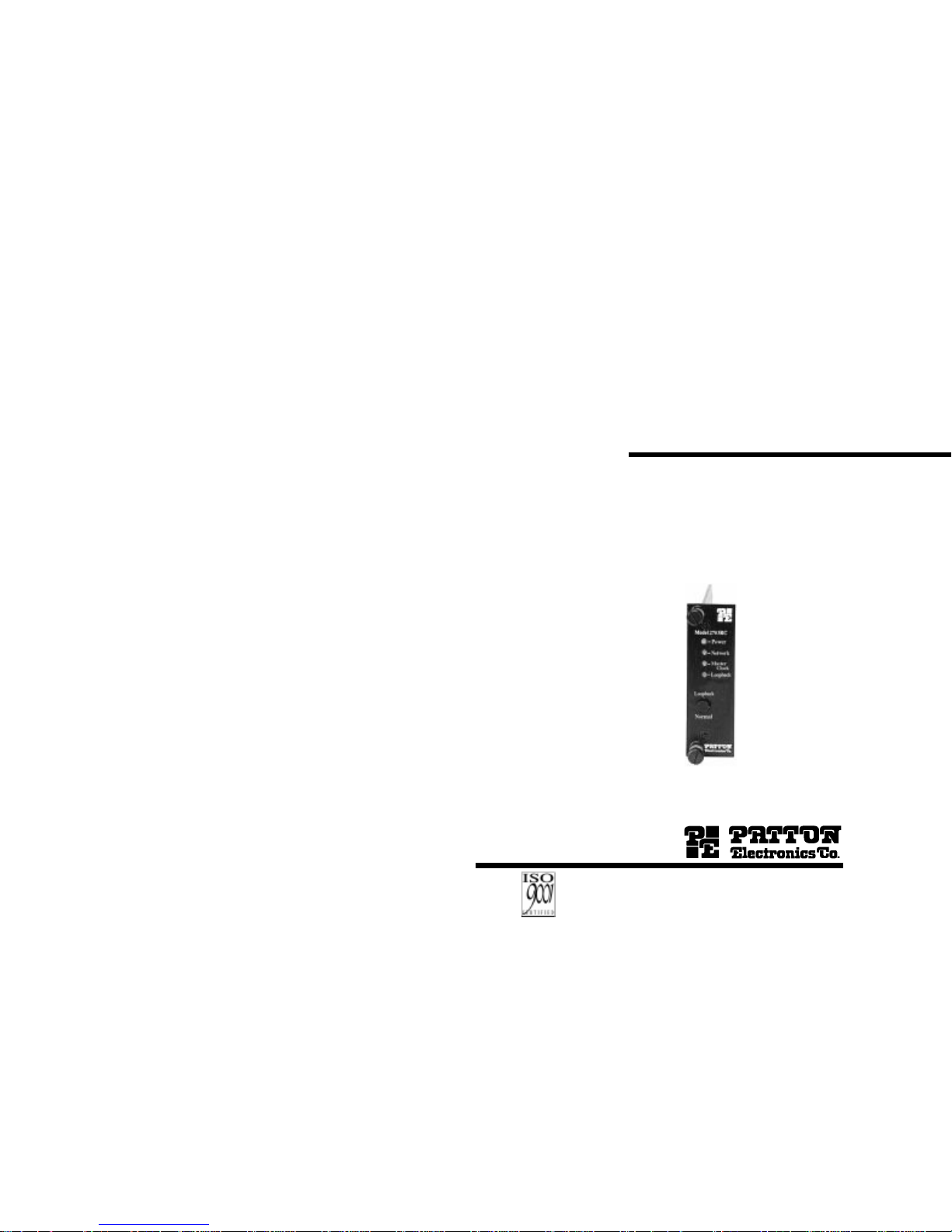
MODEL 2703RC
MegaLink-1™
G.703/E1
Digital Modem:
Rack Mount Card
SALES OFFICE
(301) 975-1000
TECHNICAL SUPPORT
(301) 975-1007
http://www.patton.com
Part# 07M2703RC-C
Doc# 031121UC
Revised 10/12/98
Dear V alued Customer,
Thank you for purchasing Patton Electronics products! We do
appreciate your business. I trust that you find this user manual helpful.
We manufacture one of the widest selections of data communications products in the world including CSU/DSU's, network termination units,
powered and self-powered short range modems, fiber optic modems, interface
converters, baluns, electronic data switches, data-line surge protectors, multiplexers, transceivers, hubs, print servers and much more. We produce these
products at our Gaithersburg, MD, USA, facility, and can custom manufacture
products for your unique needs.
We would like to hear from you. Please contact us in any of the following ways to tell us how you like this product and how we can meet your
product needs today and in the future.
Web: http://www.patton.com
Sales E-mail: sales@patton.com
Support E-mail: support@patton.com
Phone - Sales (301) 975-1000
Phone - Support (301) 975-1007
Fax: (301) 869-9293
Mail: Patton Electronics Company
7622 Rickenbacker Drive
Gaithersburg, MD 20879 USA
We are committed to a quality product at a quality price. Patton
Electronics is BABT and ISO 9001 certified. We meet and exceed the highest
standards in the industry (CE, UL, etc.).
It is our business to serve you. If you are not satisfied with any
aspect of this product or the service provided from Patton Electronics or its
distributors, please let us know.
Thank you.
Burton A.Patton
Vice President
P.S. Please tell us where you purchased this product.
_________________________________________________________
_________________________________________________________
_________________________________________________________
_________________________________________________________
_________________________________________________________
An ISO-9001
Certified Company
Page 2

1.0 WARRANTY INFORMATION
Patton Electronics warrants all Model 2703RC components to be
free from defects, and will—at our option—repair or replace the product
should it fail within one year from the first date of shipment.
This warranty is limited to defects in workmanship or materials,
and does not cover customer damage, abuse or unauthorized modification. If this product fails or does not perform as warranted, your sole
recourse shall be repair or replacement as described above. Under no
condition shall Patton Electronics be liable for any damages incurred
by the use of this product. These damages include, but are not limited
to, the following: lost profits, lost savings and incidental or consequential damages arising from the use of or inability to use this product.
Patton Electronics specifically disclaims all other warranties,
expressed or implied, and the installation or use of this product shall be
deemed an acceptance of these terms by the user.
1.1 RADIO AND TV INTERFERENCE
The Model 2703RC generates and uses radio frequency energy,
and if not installed and used properly—that is, in strict accordance with
the manufacturer’s instructions—may cause interference to radio and
television reception. The Model 2703RC has been tested and found to
comply with the limits for a Class A computing device in accordance
with the specifications in Subpart J of Part 15 of FCC rules, which are
designed to provide reasonable protection from such interference in a
commercial installation. However, there is no guarantee that interference will not occur in a particular installation. If the Model 2703RC
does cause interference to radio or television reception, which can be
determined by turning the power off or removing the card, the user is
encouraged to try to correct the interference by one or more of the following measures: moving the computing equipment away from the
receiver, re-orienting the receiving antenna and/or plugging the receiving equipment into a different AC outlet (such that the computing equipment and receiver are on different branches). In the event the user
detects intermittent or continuous product malfunction due to nearby
high power transmitting radio frequency equipment, the user is strongly
advised to take the following steps:use only data cables with an external outer shield bonded to a metal or metalized connector; and,
Configure the rear card as shown in section 3.2 of this manual.
1.2 CE NOTICE
The CE symbol on your Patton Electronics equipment indicates
that it is in compliance with the Electromagnetic Compatibility (EMC)
directive and the Low Voltage Directive (LVD) of the Union European
(EU). A Certificate of Compliance is available by contacting Technical
Support.
1
1.3 SERVICE
All warranty and nonwarranty repairs must be returned freight prepaid and insured to Patton Electronics. All returns must have a Return
Materials Authorization number on the outside of the shipping container.This number may be obtained from Patton Electronics Technical
Support: (301) 975-1007; http://www.patton.com;or, support@pat-
ton.com.
NOTE: Packages received without an RMA number will not be
accepted.
Patton Electronics' technical staff is also available to answer any
questions that might arise concerning the installation or use of your
Model 2703RC. Technical Service hours: 8AM to 5PM EST, Monday
through Friday.
2
Page 3
2.0 GENERAL INFORMATION
Thank you for your purchase of this Patton Electronics product.
This product has been thoroughly inspected by Patton’s qualified technicians. If any questions or problems arise during installation or use of
this product, please do not hesitate to contact Patton Electronics
Technical Support at (301) 975-1007.
2.1 FEATURES
• Synchronous network data rate of 2.048 Mbps
• Four Selectable DTE Rates: 256, 512, 1024, and 2048 Mbps
• EIA-530 (V.36/EIA-422 Electr ical), V.35 or X.21 terminal interfaces
•120 ohm (twisted pair) or 75 ohm (coax) network terminations
• Master and Slave (network) clocking
• Built-in local loopback test
• Front panel LED indicators for power, network,
master clock and test loop
• Mounts in Patton’s 16-slot rack chassis and 2/4/8-slot Cluster
Boxes
• Made in the U.S.A.
2.2 DESCRIPTION
The Patton
MegaLink™
Model 2703RC G.703/E1rack card modem
receives unstructured, synchronous 2.048 Mbps data from a G.703 network and sends it to a router, bridge, multiplexer or other device. The
Model 2703RC is available with two interface options: 120 Ohm twisted
pair to the network with EIA-530 (V.36/EIA-422) or V.35 (utilizing a 25
pin connector) to the terminal, or 75 Ohm dual coax to the network with
X.21 to the terminal. An additional feature allows the EIA-530 terminal
interface to be adapted to X.21 using a special DTE cable (available
from Patton).
The Model 2703RC is designed to mount in Patton’s 2U high, 16slot rack chassis or 2/4/8-slot Cluster Boxes. These have a switchable
120/240 VAC power supply (optional 48 VDC) and mount cards in a
mid-plane architecture: front “function” cards and rear “interface” cards
can be hot-swapped independently, providing great flexibility. The
Model 2703RC supports Internal (master) and Network (slave) clocking. Loopback test is built-in, and front panel LEDs monitor power, network, master clock and test loop.
3
3.0 CONFIGURATION
Two cards make up a single Model 2703RC G.703 Converter - a
front function card and a rear interface card. Each may require configuration depending upon the product application. This section describes
the location and orientation of the Model 2703RC’s configuration
switches and jumpers, and provides descriptions for all settings.
3.1 FRONT CARD CONFIGURATION
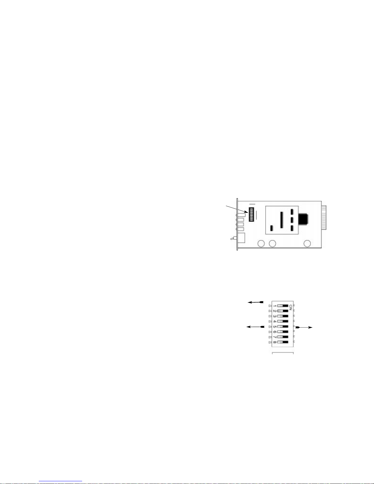
The Model 2703RC front card has a single bank of eight DIP
switches located on the top of the printed circuit board. Figure 1,
below, shows the position of the switches on the board.
Changing the DIP Switch Settings
Figure 2 shows the orientation of the DIP switches with respect to the
“ON” and “OFF” positions.
4
Figure 1. Model 2703RC board, showing jumper locations
DIP Switch
OFF ON
1
8
Figure 2. Close up of the configuration switches
NOTE: The OFF position is oriented toward the front of the Model 2703RC.
OFF
ON
Front Panel
Page 4
Switches S2 and S3: Rate Adaptation (DTE Rate)
Set Switches S2 and S3 together to allow the Model 2703 to
adapt to terminal devices that run at data rates less than 2.048 Mbps
(The network rate remains 2.048 Mbps regardless of the terminal rate
adaptation setting). The setting you select must match the data rate of
your terminal device.
S2 S3 Setting
Off Off 2.048 Mbps
On Off 1.024 Mbps
Off On 512 Kbps
On On 256 Kbps
Switches S4 and S5:
Reserved for Future Use
Switches S4 and S5 are reserved for future use and must remain
in the Off position.
Switch S6: Internal/Network Clock
Set Switch S6 to allow the Model 2703RC to provide an internal
clock, or recover the clock from the received G.703 input signal.
S6 Setting
On Model 2703RC clock is internal
Off Model 2703RC clock is recovered from the network
Switches S7 and S8:
Reserved for Future Use
Switches S7 and S8 are reserved for future use and must remain
in the Off position.
6
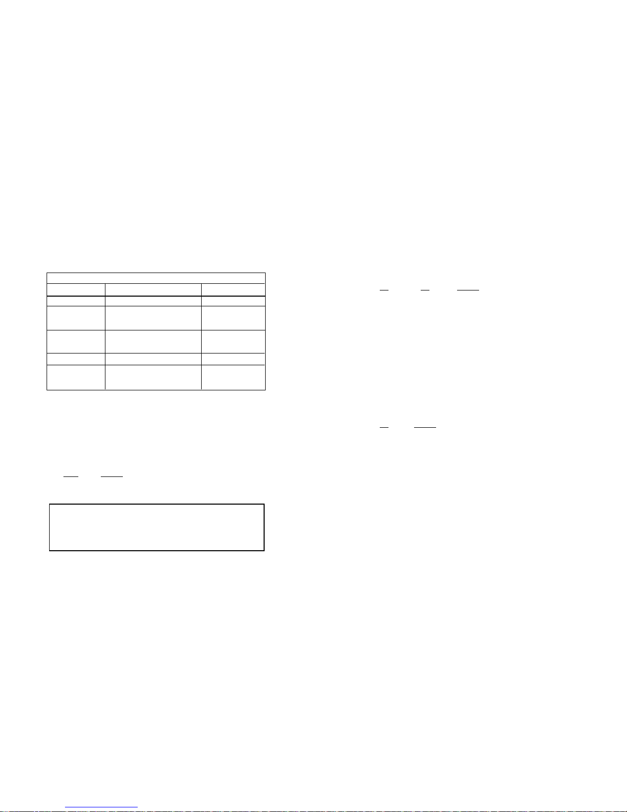
3.1 DIP Switches S1 - S8
The configuration switches on S1 - S8 may be used to set data
inversion, the DTE bit rate, and clocking modes. Default settings of S1
through S8 are shown in the table below. Descriptions of each switch
follow the table.
Switch S1: Data Inversion
Set Switch S1 to determine whether or not the data stream from
the local DTE is inverted within the Model 2703RC before being
passed to the G.703 network. You may need to invert the data stream
when you use the Model 2703RC with an imbedded G.703 device that
inverts the data on the remote end. Data inversion is typically not necessary.
S1-1
Setting
On Data inverted
Off Data not inverted
5
Position Function Factory Default
S1 Data Inversion Off Non-Inverted
S2 Rate Adaptation (DTE Rate) Off
S3 Rate Adaptation (DTE Rate) Off
S4 Off
S5 Off
S6 Clock Mode Off Network
S7 Off
S8 Off
SWITCH SUMMARY TABLE
2.048 Mbps
}
Reserved
Reserved
NOTE: The PCM data stream must be inverted if this Model
2703RC is to be connected to a standalone Model 2703
Firmware Revision B (or older) unit at 256, 512, and 1024 kbps.
The firmware version of the standalone 2703 is printed on the
bottom side of the unit.
Page 5

3.1.1 Interface Driver Board
The Model 2703RC Series features changeable Interface Driver
Boards that allow a wide range of DTE interface connections.
Supported interfaces are V.35, EIA-530, and X.21. The Interface
Driver Board plugs onto a 40 pin header (2 rows of 20 pins) on the top
side of the 2703RC PC board (See Figure 3, below).
Your 2703RC comes with an Interface Driver Board already mounted on the board. If you wish to change the electrical interface of the
2703RC, you must change the Interface Driver Board (See Appendix B
for Model Numbers).
Follow the instructions below to change the Interface Driver Board:
1. With the 2703RC pulled out of the rack or clusterbox chassis,
locate the driver board on the top of the 2703RC front card.
2. Lift the interface board gently off of the PC board.
3. Locate the correct interface on the bottom of the driver board.
For example, V.35 interface board is marked “THIS SIDE UP
FOR V .35” on one side of the board other side .
4. Plug the interface board into the 20 pin header socket with the
appropriate interface pointed UP and with the arrow pointing
toward the front panel of the Model 2703RC PC board.
5. Push the Interface Driver Board gently onto the socket and reinstall into the rack or cluster system.
3.2 REAR CARD CONFIGURATION
The Model 2703RC has two rear interface card options:
1. Model 1000RCM703120 - 120 Ohm (modular) network and
female (DB-25) terminal (Supports V.35 and V.36/EIA-422).
2. Model 1000RCM70375 - 75 ohm (dual BNC) network and
female (DB-15) terminal.
Please refer to the instructions below to configure the rear cards.
3.2.1 CONFIGURING THE 1000RCM703120 REAR CARD
The Model 1000RCM120 DB25/RJ45 Ohm rear card has five configuration jumpers (LK1 - LK5). Figure 4 (below) shows the locations of
the jumpers on the 120 Ohm rear card.
87
Figure 4. Jumper Locations for the Model 1000RCM703120 Rear Card
Figure 3. Closeup of Model 2703RC Interface Drive Board
LK4
LK3
LK2
LK1
LK5
DB-25
Connector
RJ-45
Connector
FRONT THIS SIDE UP FOR V.35
Page 6

The table below shows the factory default jumper settings for the
Model 1000RCM703120 DB25/RJ-45 rear card. Following the table is
a description of each jumper’s function and possible settings. When
configuring the jumpers, take care not to lose the individual straps.
LK1: (Receive Pair) Pin 2-to-Ground Connection
This setting determines whether or not pin 2 of the receive pair is
sent to earth ground. This connection should not
be made in most
cases.
LK1
Setting
Strap On Pin 2-to-GND Connection Made
Strap Off Pin 2-to-GND Connection Broken
LK2: Receive Shield (Pin 3)-to-Ground Connection
This setting determines whether or not the RX shield (pin 3) is
connected to earth ground. This connection may help EMC performance in some cases.
LK2
Setting
Strap On Pin 3-to-GND Connection Made
Strap Off Pin 3-to-GND Connection Broken
LK3: (Transmit Pair) Pin 4-to-Ground Connection
This setting determines whether or not pin 4 of the transmit pair is
sent to earth ground. This connection should not
be made in most
cases.
LK3
Setting
Strap On Pin 4-to-GND Connection Made
Strap Off Pin 4-to-GND Connection Broken
LK4: Clock Synchronization (EIA-530/V.35 vs. X.21)
This setting determines whether clocks are common or separate.
Separate (non-synchronized) clocks are used for the EIA-530/V.35 terminal interface. Common (synchronized) clocks are used for the X.21
terminal interface. If clocks are synchronized, a DB-25 to DB-15
adapter cable should be used between the Model 2703RC and the
X.21 terminal device (see Appendix B and Appendix C for details).
LK4
Setting
Strap On Clocks Synchronized (X.21)
Strap Off Clocks not Synchronized (EIA-530 and V.35)
LK5: DTE Signal Ground-to-Frame Ground (with Resistor)
This setting determines whether or not the DTE signal ground
(DB-25 pin 7) is connected to frame ground (pin 1) by way of a 100
ohm resistor. This connection is recommended in the EIA-530 specification as a current limiter for ground fault events.
LK5
Setting
Strap On SGND-to-FGND Connection Made
Strap Off SGND-to-FGND Connection Broken
3.2.2 CONFIGURING THE MODEL 1000RCM70375 REAR CARD
The Model 1000RCM70375 DB15/Coax Ohm rear card has two
configuration jumpers (LK1 & LK2). Figure 5 (below) shows the locations of the jumpers on the 75 Ohm rear card.
9 10
Figure 5. Jumper Locations for the Model 1000RCM70375 Rear Card
LK1
LK2
120 OHM REAR CARD JUMPERS
Jumper Function Factory Default
LK1 RX Pin 2 to GND Strap Off
LK2 RX Shield (Pin 3) to GND Strap Off
LK3 TX Pin 4 to GND Strap Off
LK4 Clock Synchronization Strap Off
LK5 (DTE) SGND to FGND Strap On
Page 7

The table below shows the factory default jumper settings for the 75
ohm rear card. Following the table is a description of each jumper’s
function and possible settings. When configuring the jumpers, take
care not to lose the individual straps.
LK1: Receive Shield-to-Ground Connection
This setting determines whether or not the RX shield is connected
to earth ground. This connection may help EMC performance in some
cases.
LK1
Setting
Strap On RX Shield-to-GND Connection Made
Strap Off RX Shield-to-GND Connection Broken
LK2: DTE Signal Ground-to-Frame Ground (with Resistor)
This setting determines whether or not the DTE signal ground
(DB-15 pin 8) is connected to frame ground (pin 1) by way of a 100
ohm resistor. This connection is recommended as a current limiter for
ground fault events.
LK2
Setting
Strap On SGND-to-FGND Connection Made
Strap Off SGND-to-FGND Connection Broken
4.0 INSTALLATION
This section describes the functions of the Model 1000R16 rack
chassis, tells how to install front and rear Model 2703RC cards into the
chassis, and provides diagrams for wiring the interface connections
correctly.
4.1 THE MODEL 1000R16 RACK CHASSIS
The Model 1000R16 Rack Chassis (Figure 6, below) has sixteen
device card slots, plus its own power supply. Measuring only 3.5” high,
the Model 1000R16 is designed to occupy only 2U in a 19” rack.
Sturdy front handles allow the Model 1000R16 to be extracted and
transported conveniently.
4.1.1 THE RACK POWER SUPPLY
The power supply included in the Model 1000R16 rack uses the
same mid-plane architecture as the modem cards. The front card of
the power supply slides in from the front, and the rear card slides in
from the rear. They plug into one another in the middle of the rack.
The front card is then secured by thumb screws and the rear card by
conventional metal screws.
11 12
Figure 6. Model 1000R16 Rack Chassis with power supply
WARNING! There are no user-serviceable parts in the
power supply section of the Model 2703RC. Voltage setting changes and fuse replacement should only be performed by qualified service personnel. Contact Patton
Electronics Technical support at (301)975-1007 for more
information.
75 OHM REAR CARD JUMPERS
Jumper Function Factory Default
LK1 RX Shield to GND Strap Off
LK2 (DTE) SGND to FGND Strap On
Page 8

4.3 CONNECTION TO THE G.703 NETWORK
The Model 2703RC supports 2.048 Mbps communication over an
unstructured G.703 network. Both 120 ohm and 75 ohm interface
cards are available (see Figure 7, below).
4.3.1 TWISTED PAIR (120 OHM) CONNECTION
The Model 2703RC DB25/R45 rear card (Model 1000RCM703120)
is equipped with a single RJ-45 jack for connection to a 120 ohm twisted pair G.703 network interface. The pinout of this jack is as follows:
RJ-45
Pins SIGNAL
1 & 2 . . . . . . . . . . . . Receive pair (from network)
3. . . . . . . . . . . . . . . Shield reference point
4 & 5 . . . . . . . . . . . . Transmit pair (to network)
6. . . . . . . . . . . . . . . Shield reference point
7. . . . . . . . . . . . . . . Not used
8. . . . . . . . . . . . . . . Not used
14
Switching the Power Supply On and Off
The power supply on/off switch is located on the front panel.
When plugged in and switched on, a red front panel LED will glow.
Since the Model 1000R16 is a “hot swappable”rack,
it is not neces-
sary for any cards to be installed before switching on the power supply
.
The power supply may be switched off at any time without harming the
installed cards.
NOTE: Please refer to the Model 1000RP Series User Manual
AC
and DC Rack Mount Power Supplie
s for fuse and power card
replacement information.
4.2 INSTALLING THE MODEL 2703RC INTO THE CHASSIS
The Model 2703RC is comprised of a front card and a rear card.
The two cards meet inside the rack chassis and plug into each other
by way of mating 50 pin card edge connectors. Use the following
steps as a guideline for installing each Model 2703RC into the rack
chassis:
1. Slide the rear card into the back of the chassis along the
metal rails provided.
2. Secure the rear card using the metal screws provided.
3. Slide the card into the front of the chassis. It should meet the
rear card when it’s almost all the way into the chassis.
4. Push the front card
gently
into the card-edge receptacle of
the rear card. It should “click” into place.
5. Secure the front card using the thumb screws.
NOTE: Since the Model 1000R16 chassis allows “hot swapping”
of cards, it is
not necessary to power down
the rack when you
install or remove a Model 2703RC.
13
Notice! Any modular twisted pair cable connected to
the rear card must be shielded cable, and the outer shield
must be properly terminated to a shielded modular plug
on both ends of the cable.
Figure 7. Rear interface card options for the Model 2703RC
DB-25 Female
DB-15 Female
Model
1000RCM703120
Model
1000RCM70375
RJ-45 (120 Ohm)
Dual BNC (75 Ohm)
TX
RX
Page 9

5.0 OPERATION
Once you have configured each Model 2703RC and connected the
cables, you are ready to operate the units. Section 5.0 describes the
power-up procedure, LED status indicators and the built-in loopback
test modes.
5.1 POWER-UP
There is no power switch on the Model 2703RC: Power is automatically applied to the Model 2703RC when its card-edge connector
makes contact with the chassis’ mid-plane socket, and when the chassis’ power supply is turned on.
Note:The Model 2703RC is a “hot
swappable”card—it will not be damaged by plugging it in or removing
it while the rack is powered up.
5.2 LED STATUS MONITORS
The Model 2703RC features four front panel LEDs that monitor
and power, network connection, master clock and loopback. Figure 8
(below) shows the front panel location of each LED. Following Figure
7 is a description of each LED’s function.
Power Glows red when the Model 2703RC receives oper
ational power.
Network Glows green when the Model 2703RC is receiving
correctly encoded data from the line interface
equipment.
Master Clock Glows green when the Model 2703RC is
configured as the master clock unit.
Loopback Glows green when the Model 2703RC is in
loopback mode.
4.3.2 DUAL COAX BNC (75 OHM) CONNECTION
The Model 2703RC DB15/Coax rear card is equipped with dual
female BNCs (TX and RX) for connection to a 75 ohm dual coax G.703
network interface. The outer conductor of the coax cables is isolated
from system earth ground.
4.4 CONNECTION TO THE TERMINAL DEVICE
The Model 2703RC rear cards are wired as Data CircuitTer minating Equipment (DCE) and are designed to connect directly to
Data Terminal Equipment (DTE).
4.4.1 EIA-530 (RS422/V.36) and V.35 TERMINAL CONNECTION
The DB25 connector of the Model 1000RCM703120 rear card is
configured as DCE (see the wiring diagram in Appendix C). To connect to a V.35 or RS-422/V.36 DTE device, use a
straight-through
DB25 cable. NOTE: The 120 ohm rear card must be set for non-synchronized clocking (See Section 3.2.1) in order to support the EIA-530 or
V.35 interfaces.
4.4.2 X.21 TERMINAL CONNECTION
The DB15 connector of the Model 2703RC is equipped with a
female DB-15 connector and is, wired according to the ITU/CCITT X.21
standard (see the wiring diagram in Appendix C). To connect to to an
X.21 terminal (DTE), use a
straight-through
DB-15 cable.
Note: The 120 ohm rear card can also be used with X.21 ter minal
devices. To do this, the card must be set for synchronized clocking
(See Section 3.2.1), a DB-25 to DB-15 adapter cable must be
used. See Appendix B for the adapter cable part numbers. Or,
you may construct your own cable using the diagrams in
Appendix C.
15 16
Figure 8. Model 2703RC front panel, showing LED indicators.
Notice! Any coaxial cable connected to the dual coax rear
card must incorporate an outer shield that has no less than
90% coverage.
Notice! Any terminal cable connected to the Model 2703RC
must be shielded cable, and the outer shield must be 360
degree bonded–at both ends–to a metal or metalized backshell.
Page 10

APPENDIX A
MODEL 2703RC SPECIFICATIONS
Network Interface: G.703
Network Rate: 2.048 Mbps
Network Connectors: Two BNC (75 Ohm) or one modu-
lar RJ-45 connector (120 Ohm)
Terminal Interface: EIA-530 (RS-422/V.36), or V.35
on DB-25 female or ITU/CCITT
X.21 on DB-15 female
Internal Interface: Connection to Model 1000R16
rack chassis via 50 pin male card
edge
Terminal Rate: 256, 512, 1024, 2048 kbps
Diagnostics: Loopback Test
Indicators: LEDs for power, network, master
clock and loopback test
Clocking: Master Internal , Slave (Recovered
from the G.703 Network)
Receiver Sensitivity: -10 dB (0dB = 2.4V Peak)
Temperature Range: 0-60°C (32-140°F)
Altitude: 0-15,000 feet
Humidity: 5 to 95% noncondensing
Front Card Dimensions: 0.95”W x 3.1”H x 5.4”L
Rear Card Dimensions: 0.95”W x 3.1”H x 2.8”L
5.3 LOOPBACK TEST (LAL)
The Model 2703RC is equipped with a Local Analog Loopback
(LAL) mode to assist in evaluating the operation of the local Model
2703RC. Any data sent to the local Model 2703RC in this test mode
will be echoed (returned) back to the user device. For example, characters typed on the keyboard of a terminal will appear on the terminal
screen.
To perform a LAL test, follow these steps:
A. Activate LAL by moving the front panel toggle switch UP and
holding it in the “Loopback” mode. The “Loop” LED should
glow. Once LAL is activated, the Model 2703RC transmit
output is connected to its own receiver. (Note: The front
panel switch is spring loaded, so it will return to “Normal”
operating mode when pressure is released.)
B. Verify that the data terminal equipment is operating properly
and can be used for a test. If a fault is indicated, call a
technician or replace the unit.
C. Perform a BER (bit error rate) test on each unit. If the BER
test equipment indicates no faults, but the data terminal indi
cates a fault, follow the manufacturer’s checkout procedures
for the data terminal. Also, check the interface cable between
the terminal and the Model 2703RC.
17
18
Page 11

APPENDIX C
MODEL 2703RC INTERFACE STANDARDS
X.21 Interface
DB-15 Female Connector
DB15 Female
Pin Signal Source
1 Shield -
2 Transmit (a) DTE
3 Control (a) DTE
4 Receive (a) DCE
5 Indication (a) DCE
6 System Clock (a) DCE
7- 8 Signal Ground 9 Transmit (b) DTE
10 Control (b) DTE
11 Receive (b) DCE
12 Indication (b) DCE
13 System Clock (b) DCE
14 - 15 - -
APPENDIX B
MODEL 2703RC FACTORY REPLACEMENT PARTS
The Patton Model 2703RC rack system features interchangeable
rear cards, power cords/fuses for international various operating environments and other user-replaceable parts. Model numbers, descriptions and prices for these parts are listed below:
Patton Model # Description
1000RPEM..........................120/240V Rear Power Entry Module
1000RPSM..........................120/240V Front Power Supply Module
1000RPEM-DC ...................DC Rear Power Entry Module
1000RPSM-48A..................48V Front Power Supply Module
1000RPEM-V......................120/240V CE Compliant Rear Power
Entry Module
1000RPSM-V......................120/240V CE Compliant Front Power
Supply Module
1000RCM703120 EIA-530/RJ45 120 Ohm Rear Card
1000RCM70375 X.21/Dual Coaxial 75 Ohm Rear Card
0805US...............................American Power Cord
0805EUR.............................European Power Cord CEE 7
0805UK...............................United Kingdom Power Cord
0805AUS.............................Australia/New Zealand Power Cord
0805DEN.............................Denmark Power Cord
0805FR ...............................France/Belgium Power Cord
0805IN.................................India Power Cord
0805IS.................................Israel Power Cord
0805JAP..............................Japan Power Cord
0805SW ..............................Switzerland Power Cord
0516FPB1...........................Single Width Blank Front Panel
0516FPB4...........................4-Wide Blank Front Panel
0516RPB1...........................Single Width Blank Rear Panel
0516RPB4...........................4-Wide Blank Rear Panel
056S1..................................Set of 16 #4 pan head screws/washers
10-25M/15F-1......................Cable, 6ft, DB-25 male to DB-15
female
10-25M/35F-1......................Cable, 6ft, DB-25 male to M/34 female
10-25M/35M-1.....................Cable, 6ft, DB-25 male to M/34 male
20
21
Page 12

APPENDIX C
MODEL 2703RC INTERFACE STANDARDS
EIA-530 & V.35 Interface
DB25 Female Connector
Pin Signal Source
1 FG (Frame Ground) -
2 TD(Transmit Data) DTE
3 RD (Receive Data) DCE
4 RTS (Request to Send) DTE
5 CTS (Clear to Send) DCE
6 DSR (Data Set Ready) DCE
7 SGND (Signal Ground) 8 CD (Carrier Detect) DCE
9 RC/ (Receiver Clock-B) DCE
10 CD/ (Carrier Detect-B) DCE
11 XTC/(External Tr ansmit Clock) DTE
12 TC/ (Transmit Clock-B) DCE
13 CTS/ (Clear to Send) DCE
14 TD/ (Transmit Data-B) DTE
15 TC (Transmit Clock-A) DCE
16 RD (Receive Data) DCE
17 RC (Receiver Clock) DCE
18 LLB (Local Line Loop) DTE
19 RTS/ (Request to Send) DTE
20 DTR (Data Terminal Ready) DTE
21 RDL (Remote Digital Loop) DTE
22 DSR/ (Data Set Ready) DCE
23 DTR/ (Data Terminal Ready) DTE
24 XTC (External Transmit Clock) DTE
25 TM (Test Mode) DTE
Copyright © 1998
Patton Electronics Company
All Rights Reserved
Dear V alued Customer,
Thank you for purchasing Patton Electronics products! We do appreciate
your business. I trust that you find this user manual helpful.
We manufacture one of the widest selections of data communications
products in the world including CSU/DSU's, network termination units, powered and self-powered short range modems, fiber optic modems, interface converters, baluns, electronic data switches, data-line surge protectors, multiplexers, transceivers, hubs, print servers and much more. We produce these products at our Gaithersburg, MD, USA, facility, and can custom manufacture
products for your unique needs.
We would like to hear from you. Please contact us in any of the following
ways to tell us how you like this product and how we can meet your product
needs today and in the future.
Web: http://www.patton.com
Sales E-mail: sales@patton.com
Support E-mail: support@patton.com
Phone - Sales (301) 975-1000
Phone - Support (301) 975-1007
Fax: (301) 869-9293
Mail: Patton Electronics Company
7622 Rickenbacker Drive
Gaithersburg, MD 20879 USA
We are committed to a quality product at a quality price. Patton
Electronics is BABT and ISO 9001 certified. We meet and exceed the highest
standards in the industry (CE, UL, etc.).
It is our business to serve you. If you are not satisfied with any aspect of
this product or the service provided from Patton Electronics or its distributors,
please let us know.
Thank you.
Burton A.Patton
Vice President
P.S. Please tell us where you purchased this product.
_________________________________________________________
_________________________________________________________
_________________________________________________________
_________________________________________________________
_________________________________________________________
22
 Loading...