

Page 1
USER
MANUAL
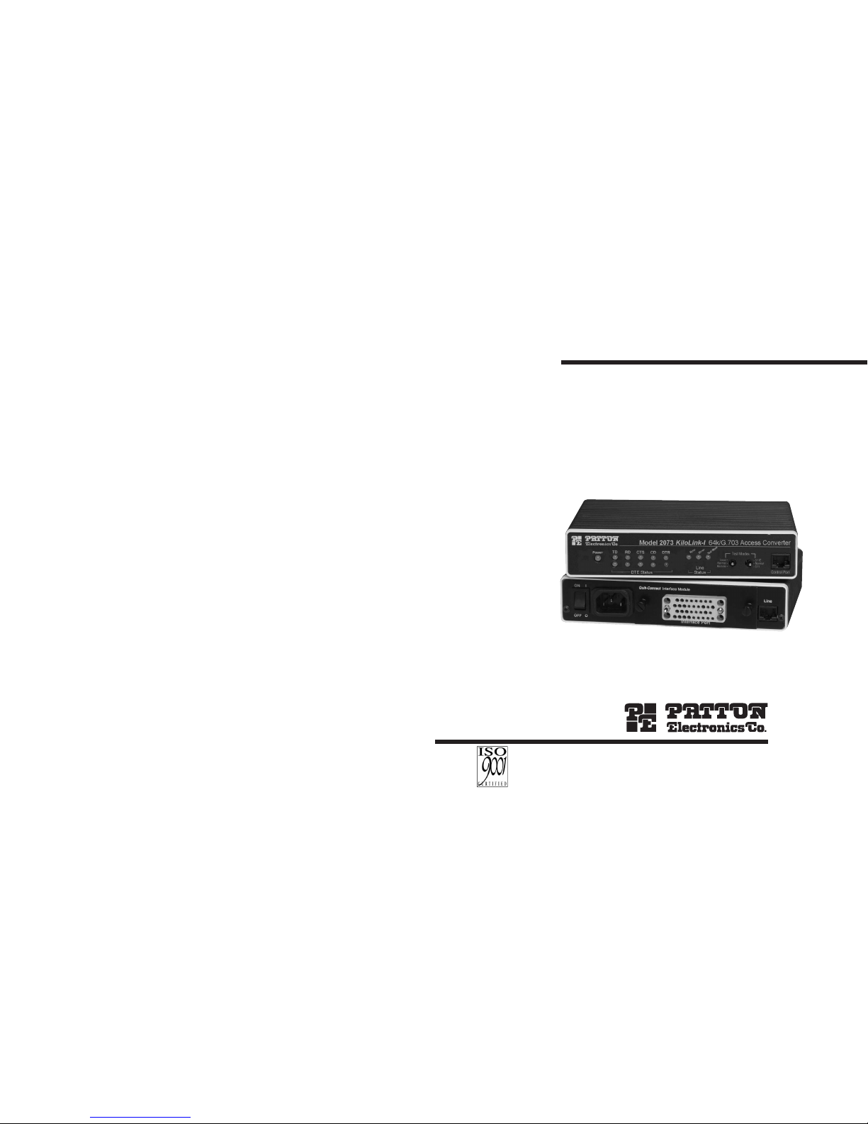
MODEL 2073
Kilo-Link™
64k/G.703 Access
Converter/Rate Adapter
Part# 07M2073-A
Doc# 0311091UA
Revised 12/4/99
SALES OFFICE
(301)975-1000
TECHNICAL SUPPORT
(301)975-1007
http://www.patton.com
An ISO-9001
Certified
Company
Page 2

TTAABBLLEE OOFF CCOONNTTEENNTTSS
Section Page
1.0 Warranty Information.............................................................2
1.1 Radio and TV Interference
1.2. CE Notice
1.3 Service
2.0 General Information...............................................................4
2.1 Features
2.2 Description
3.0 Configuration .........................................................................5
3.1 Configuring the Hardware DIP Switches
3.1.1 Configuration DIP Switch Set “S1”
3.1.2 Configuration DIP Switch Set S2”
4.0 Installation ...........................................................................10
4.1 Connecting the Twisted Pair Interface
4.2 Connecting the Serial Port
4.2.1 Changing
QuikConnect™
Modules
4.2.2 Connecting a “DTE” Device
4.2.3 Connecting a “DCE” Device
4.2.4 Configuring the X.21
QuikConnect™
Module
4.3 Connecting Power
4.3.1 Connecting to an AC Power Source
4.3.2 Connecting to a DC Power Source
5.0 Operation .............................................................................15
5.1 Power-Up
5.2 LED Status Monitors
5.3 Test Modes
5.3.1 Operating Local Analog Loopback (LAL)
5.3.2 Operating Remote Digital Loopback (RDL)
5.3.3 Using the V.52 (BER) Test Pattern Generator
Appendix A - Specifications........................................................19
Appendix B - Factory Replacement Parts and Accessories.......20
Appendix C - Interface Pin Assignments....................................21
1
11..00 WWAARRRRAANNTTYY IINNFFOORRMMAATTIIOONN
Patton Electronics warrants all Model 2073 components to be
free from defects, and will—at our option—repair or replace the product should it fail within one year from the first date of shipment.
This warranty is limited to defects in workmanship or materials,
and does not cover customer damage, abuse or unauthorized modification. If this product fails or does not perform as warranted, your sole
recourse shall be repair or replacement as described above. Under no
condition shall Patton Electronics be liable for any damages incurred
by the use of this product. These damages include, but are not limited
to, the following: lost profits, lost savings and incidental or consequential damages arising from the use of or inability to use this product.
Patton Electronics specifically disclaims all other warranties,
expressed or implied, and the installation or use of this product shall
be deemed an acceptance of these terms by the user.
1.1 RADIO AND TV INTERFERENCE
The Model 2073 generates and uses radio frequency energy, and
if not installed and used properly—that is, in strict accordance with the
manufacturer's instructions—may cause interference to radio and television reception. The Model 2073 has been tested and found to comply with the limits for a Class A computing device in accordance with
the specifications in Subpart J of Part 15 of FCC rules, which are
designed to provide reasonable protection from such interference in a
commercial installation. However, there is no guarantee that interference will not occur in a particular installation. If the Model 2073 does
cause interference to radio or television reception, which can be determined by disconnecting the unit, the user is encouraged to try to correct the interference by one or more of the following measures: moving the computing equipment away from the receiver, re-orienting the
receiving antenna and/or plugging the receiving equipment into a different AC outlet (such that the computing equipment and receiver are
on different branches).
1.2 CE NOTICE
The CE symbol on your Patton Electronics equipment indicates
that it is in compliance with the Electromagnetic Compatibility (EMC)
directive and the Low Voltage Directive (LVD) of the European Union
(EU). A Certificate of Compliance is available by contacting Technical
Support.
2
Page 3

1.3 SERVICE
All warranty and non-warranty repairs must be returned freight
prepaid and insured to Patton Electronics. All returns must have a
Return Materials Authorization number on the outside of the shipping
container. This number may be obtained from Patton Electronics
Technical Service at:
tel: (301)975-1007
email: support@patton.com
www: http://www.patton.com
Patton Electronics' technical staff is also available to answer any
questions that might arise concerning the installation or use of your
Model 2073. Technical Service hours: 8AM to 5PM EST, Monday
through Friday.
3
22..00 GGEENNEERRAALL IINNFFOORRMMAATTIIOONN
Thank you for your purchase of this Patton Electronics product.
This product has been thoroughly inspected and tested and is warranted for One Year parts and labor. If any questions or problems arise
during installation or use of this product, please do not hesitate to contact Patton Electronics Technical Support at (301) 975-1007.
2.1 FEATURES
• Bi-directionally converts V.24, X.21,V.35 or 10 BaseT to co-directional G.703
• LED indicators monitor Test Mode and Synchronization
• Internal, external or network clocking options
• Test Mode controlled by switch or by local DTE (V.24 and V.35
Versions Only)
• Complies with CCITT/ITU G.823 Jitter Control Specifications
• Built-in surge protection and transfor mer isolation
• Point-to-Point distance up to 5250 ft (1600m) on 24 AWG twisted
pair
• 120 ohm (twisted pair) network termination
2.2 DESCRIPTION
The Patton Model 2073 standalone interface converter/rate
adapter allow a synchronous V.24, V.35, X.21 or ether net device to
communicate bi-directionally over the G.703 co-directional PCM network. Supporting internal, external DTE timing or G.703 network generated timing, the Model 2073 is perfect for networking applications
that require speeds of 9600 bps to 64 kbps. The Quick-Connect style
of interchangeable interface modules for the 2073 allow var ious physical and electrical interfaces to connect to the 64K synchronous G.703
network.
A 120 ohm twisted pair telephone port provides the interface for
the G.703 network. Additionally, 75 ohm terminations can be made
using the Patton Model 460 (G.703 balun).
Diagnostics include Local Loopback and G.703 Loopback testing.
Synchronous clock jitter is attenuated in accordance with the G.823
specification.
4
NOTE: Packages received without an RMA number will not be
accepted.
Page 4

33..00 CCOONNFFIIGGUURRAATTIIOONN
The Model 2073 is equipped with two sets of eight DIP switches,
which allow configuration of the unit for a wide variety of applications.
This section describes switch locations and explains all possible configurations.
3.1 CONFIGURING THE HARDWARE DIP SWITCHES
The 16 external switches are grouped into two eight-switch sets,
and are externally accessible from the underside of the Model 2073.
The two sets of DIP switches on the underside of the Model 2073
will be referred to as S1 and S2. As Figure 2 shows, the orientation of
all DIP switches is the same with respect to “ON” and “OFF” positions.
5
Figure 2. Close Up of Configuration Switches (all sets are identical in appearance)
Figure 1. Underside of Model 2073, Showing Location of DIP Switches
3.1.1 Configuration DIP Switch Set “S1”
Switches S1-1 thru S1-4: DTE Data Rates
The DTE synchronous and asynchronous data are determined by
the combined switch settings of S1-1,S1-2,S1-3, and S1-4. The following table lists all the possible switch combinations and the corresponding DTE data rates:
NOTE1: The four data rate configuraton switches are ignored when Octet
Timing Mode is selected (S2-1 is set to the “On” position, D8=1). In Octet
Timing Mode, the data rate defaults to 128kbps.
NOTE2: Asynchronous rates are 9600, 14,400, and 19,200. To run in asynchro-
nous mode, set the 2073 for 64K synchronous to over sample the data bits.
6
OFF
ON
Rear
Front
Data Rate S1-1 S1-2 S1-3 S1-4
9600 Off On On Off
14.4 Off On On On
19.2 On Off Off Off
28.8 On Off Off On
32 On Off On Off
38.4 On Off On On
48 On On Off Off
56 On On Off On
57.6 OnOnOnOff
64 On On On On
Position Function Factory Default
S1-1 DTE Data Rate On
S1-2 DTE Data Rate On
S1-3 DTE Data Rate On
S1-4 DTE Data Rate On
S1-5 Transmit Clock Source On
S1-6 Transmit Clock Source Off
S1-7 Reserved Off
S1-8 V.54 Prep Phase Reception On Enabled
S1 Summary Table
}
64kbps
Network (Normal)
}
Page 5

7
3.1.2 Configuration DIP Switch Set “S2”
Switch S2-1: Clear Channel or Octet Timing Mode
Use Switch S2-1 to control the G.703 timing mode. When S2-1 is
set to the “Off” position, a clear channel mode of operation is selected. In this mode, only user data is transmitted to and from the DTE
interface at any one of the data rates mentioned in section 3.1.1.
When S2-1 is set to the “On” position, 128K octet timing mode is
selected. In this mode 64 kbps octet timing information is embedded
within the 64 kbps user data, thus creating a 128 kbps synchronous
data stream to and from the DTE.
NOTE: Octet timing mode requires synchronous, 128 kbps DTE operation.
When octet timing mode is selected (S2-1=”On”), all data rate selection switches are ignored.
8
Switches S1-5 and S1-6: Transmit Clock Source
Use Switches S1-5 and S1-6 to configure the 2073 transmit clock
source. In campus applications, in which two Model 2073s operate as
short range modems, set one unit for internal or external clock, and the
other unit for Network (Campus) Clock. When the Model 2073 terminates a 64kbps G.703 line and provides a serial interface to customer
premises equipment, set the unit for Network (Normal) Clock.
NOTE: Switches S1-5 and S1-6 determine the source of clocking across the
G.703 connection. Therefore, this option must be defined in both
Asynchronous and Synchronous DTE applications. External transmit clock
source is not a valid setting for asynchronous applications.
Switch S1-8: Local V.54 Preparatory Phase Reception
Enable/Disable
Use switch S1-8 to control the reception of the V.54 remote digital
loopback preparatory phase bit pattern by the local Model 2073. When
this switch is “On”, the local 2073 will respond to any V.54 loopback
requests that are received from the G.703 network. This is the normal
setting. This setting will allow the local Model 2073 to enter V.54 loopback when a valid V.54 preparatory phase bit pattern is received from
the G.703 network.
When S1-8 is “Off”, the local Model 2073 will ignore any V.54 loopback requests that are received from the G.703 network. This mode
can be used to prevent the local Model 2073 from entering V.54 loopback mode indadvertently, due to bit streams that resemble the V.54
preparatory phase pattern. Even if S1-8 is “Off”, the local Model 2073
may still initiate a V.54 loopback request.
Clear Channel or Octet Timing Mode S2-1
Clear Channel Mode Off
Octet Timing Mode On
V.54 Prep Phase Reception S 1-8
Disabled Off
Enabled On
Transmit Clock Source S1-5 S1-6
Internal Off Off
External Off On
Network (Normal) On Off
Network (Campus) On On
Position Function Factory Default
S2-1 Timing Mode Off Clear Channel
S2-2 BPV Transmit Control Off BPV not inserted
S2-3 Front Panel Switch On Enabled
S2-4 DTE Test Mode On Acknowledged
S2-5 Reserved Off
S2-6 Reserved Off
S2-7 Reserved Off
S2-8 Reserved Off
S2 Summary Table
Page 6

9
Switch S2-2: G.703 Bi-Polar Violation (BPV) Transmit Control
Use switch S2-2 to determine whether or not the Model 2073 will
insert BPV’s into the transmitted G.703 data stream.
Switch S2-3: Front Panel Switch Enable/Disable
Use Switch S2-3 to disable or enable the front panel switches.
Switch S2-4: DTE Test Mode Request Enable/Disable
Use Switch S2-4 to determine whether or not the Model 2073 will
respond to test mode requests (LAL or RDL) from the DTE.
10
44..00 IINNSSTTAALLLLAATTIIOONN
The Model 2073 is designed for 4-wire, full duplex communication
over a co-directional 64 kbps G.703 clear channel network dedicated
twisted pair. This section describes the proper connection of the line
interface, the DTE (terminal) interface, and AC/DC power.
4.1 Connecting to a PCM Network Channel
The RJ-45 port on a model 2073 is pre-wired for direct connetion to
the G.703 PCM network. Connect the RJ-45 port of the Model 2073 to
the RJ-45 jack provided by your digital service carrier using a straight
through twisted pair cable between 19 and 26 AWG. The signal pin
relationships are shown in Figure 4 below.
Figure 4. 64K G.703 Interface
4.2 Connection Over Private Twisted Pair
If you wish to connect the Model 2073 to another Model 2073 (or
compatible G.703 device) over private twisted pair, make the connection between the two devices using a crossover cable pinned according to the diagram below.
RJ-45 Cable (8-Wire)
SIGNAL PIN# PIN# SIGNAL
RX+ 1----------5 TX+
RX- 2----------4 TXTX+ 5----------1 RX+
TX- 4----------2 RXShield 3----------3 Shield
Shield 6----------6 Shield
1 (RX+)
2 (RX-)
3 (N/C)
4 (TX-)
5 (TX+)
6 (N/C)
7 (N/C)
8 (N/C)
1
2
3
4
5
6
7
8
Front Panel Switch Operation S2-3
Disabled Off
Enabled On
DTE Test Mode Requests S2-4
Ignored Off
Acknowledged On
BPV Transmit Behaviour S2-2
BPVs not inserted into G.703 data stream Off
BPVs insterted into G.703 data stream On
NOTICE! The G.703 line surge protection on this unit was
installed for circuit protection only. By no means does this
include the preservation of signal quality during a large
surge.
Page 7

11
4.2 CONNECTING THE SERIAL PORT
The serial port interface on the Model 2073 uses interchangeable
QuikConnect™
Modules. Each
QuikConnect™
Module has a 50-pin
card edge connector on one side and a serial port interface on the
other. The drawing below shows how a
QuikConnect™
Module plugs
into the back of the Model 2073. Figure 4 below shows how a
QuickConnect
TM
Module plugs into the back of the Model 2073.
4.2.1 Changing
QuikConnect™
Modules
When you purchase a particular version of the Model 2073, it
should be shipped to you with the appropriate
QuikConnect™
Module
already installed. If you need to install a different
QuikConnect™
Module, follow these steps:
Removing the Existing
QuikConnect™
Module
1) Turn the power switch off. Leave the power cord plugged into
a grounded outlet to keep the unit grounded.
2) Loosen the two thumbscrews on the module by turning them
counterclockwise.
3) Grasp the two thumbscrews and gently pull the module from
the unit. Apply equal force to the thumbscrews to keep the
module straight during the removal process
Installing the New
QuikConnect™
Module
1) Make sure the power switch is off. Leave the power cord
plugged into a grounded outlet to keep the unit grounded.
2) Hold the module with the faceplate toward you and align the
module with the guide slots in the rear panel of the Model
2073.
3) While keeping the module’s faceplate parallel with the Model
2073 rear panel, slide the module straight in – so that the card
edge contacts line up with the socket inside the chassis.
4) With the card edge contacts aligned with the socket, firmly seat
the module by using your thumbs to apply pressure directly to
the right and left edges of the module faceplate. Applying
moderate and
even
pressure should be sufficient to seat the
module. You should hear it “click” into place.
5) To secure the module in place, push the thumbscrews into the
chassis and turn the screws clockwise to tighten.
4.2.2 Connecting to a “DTE” Device
The serial port on most
QuikConnect™
interface modules (all
except the X.21 module) is hard-wired as a DCE. Therefore these
modules “want” to plug into a DTE such as a terminal, PC or host.
When making the connection to your DTE device, use a straight
through cable of the shortest possible length—we recommend 6 feet
or less. When purchasing or constructing an interface cable, please
refer to the pin diagrams in Appendix C as a guide.
4.2.3 Connecting to a “DCE” Device
If the Model 2073’s QuikConnect™ interface module is hard-wired
as a DCE (all except the X.21 module), you must use a
null modem
cable when connecting to a modem, multiplexer or other DCE device.
This cable should be of the shortest possible length—we recommend 6
feet or less. When purchasing or constructing a null modem interface
cable, use the pin diagrams in Appendix C as a guide.
12
NOTE: The card edge connector should meet the socket when
it is almost all the way into the chassis. If you encounter a lot of
resistance, remove the module and repeat steps 2 & 3.
FIgure 5. Installation of Model 2073 Plug-in Serial Interface Module
Page 8

4.2.4 Configuring the X.21
QuikConnect™
Module
The serial port on the X.21
QuikConnect™
Module is default wired
as a DCE, but may be switched to a DTE. This is done by reversing
the orientation of the DCE/DTE strap, as described below:
To reverse DCE/DTE orientation, remove the module according to
the instructions in Section 4.2.1. The DCE/DTE strap is located on
the bottom side of the module’s PC board. The arrows on the top of
the strap indicate the configuration of the X.21 port (for example, if the
DCE arrows are pointing toward the DB-15 connector, the X.21 port is
wired as a DCE). Reverse the DCE/DTE orientation by pulling the
strap out of its socket, rotating it 180º, then plugging the strap back
into the socket. You will see that the DCE/DTE arrows now point in
the opposite directions, showing the new configuration of the X.21
port. Reinstall the module according to the instructions in Section
4.2.1.
4.3 CONNECTING POWER
The Model 2073 is available with two power supply options:
Universal Interface AC Power Supply option (Model 2073-UI)
operates in environments ranging from 100 to 253 VAC, with no reconfiguration necessary (see Appendix B for available domestic and
international power cords).
DC Power Supply option (Model 2073-DC) operates in 48 VDC
environments and is equipped with a 3-pin “terminal strip” style connector.
4.3.1 Connecting to an AC Power Source
The Universal Interface AC Supply is equipped with a male IEC-
320 power connection. A domestic (US) power supply cord is supplied with the unit at no extra charge. To connect the standard or universal power supply, follow these steps:
1) Attach the power cord (supplied) to the shrouded male IEC320 connector on the rear of the Model 2073.
2) Plug the power cord into a nearby AC power outlet.
3) Turn the rear power switch ON.
13
4.3.2 Connecting to a DC Power Source
The 48 VDC power supply option uses a 3-pin terminal block with
spring-type connectors. Please refer to the Model 1090 Series Service
Manual for the power line voltage connections.
14
NOTE: Pin-out requirements for null modem applications vary
widely between manufacturers. If you have any questions about
a specific application, contact Patton Electronics Technical
Support.
WARNING! There are no user-serviceable parts in the
power supply section of the Model 2073. Fuse replacement
should only be performed by qualified service personnel.
Contact Patton Electronics Technical support at
(301)975-
1007
, via our web site at http://www.patton.com, or by e-mail
at support@patton.com, for more information.
Page 9

55..00 OOPPEERRAATTIIOONN
Once the Model 2073 is properly configured and installed, it
should operate transparently. This sections describes power-up, reading the LED status monitors, and using the built-in loopback test
modes.
5.1 POWER-UP
To apply power to the Model 2073, first be sure that you have
read Section 4.3, and that the unit is connected to the appropriate
power source. Then power-up the unit using the rear power switch.
Figure 5 (below) shows the front panel location of each LED. A
description of the each LEDs funtion is below Figure 5.
Figure 5. Model 2073 Front Panel
5.2 LED STATUS MONITORS
The Model 2073 features13 front panel LEDs that monitor power,
the DTE signals, network connection and test modes. The figure
below shows the front panel location of each LED. Following the figure below is a description of each LEDs function.
TD & RD Glows yellow to indicate an idle condition of Binary
“1” data on the respective terminal interface signals. Green indicates Binary “0” data
CTS Glows green to indicate that the Clear to Send sig-
nal from the modem is active.
CD Glows yellow if no carrier signal is being received
from the remote modem. Green indicates that the
remote modem’s carrier is being received.
RTS Glows green to indicate that the Request to Send
signal from the terminal is active.
ER - flashes once to indicate that a CRC error has
occurred (during normal operation) or bit errors
have occurred (during 511/511E tests).
15
TM glows yellow to indicate that the Model 2073
has been placed in Test Mode. The unit can be
placed in test mode by the local user or by the
remote user.
SYNC Glows green to indicate a valid G.703 connection.
5.3 TEST MODES
The Model 2073 offers two V.54 loop diagnostics: Local Analog
Loopback and Remote Digital Loopback. These tests can be activated
physically from the front panel, or via signals on the
QuickConnect
TM
interface.
5.3.1 Operating Local Analog Loopback (LAL)
The Local Line Loopback (LAL) test checks the operation of the
local Model 2073, and is performed separately on each unit. Any data
sent to the local Model 2073 in this test mode will be echoed
(returned) back to the user device (i.e, characters typed on the keyboard of a terminal will appear on the terminal screen).
Figure 6. Local Line Loop
To perform a Local Analog Loopback test, follow these steps:
1. Notify the G.703 Service provider that you wish to perform a
G.703 Loop test.
2. Move the front panel toggle switch UP to “Local.
3. Verify that the data terminal equipment is operating properly
and can be used for a test.
4. Perform a V.52 BER (bit error rate) test as described in Section
5.3.3. If the BER test equipment indicates no faults, but the
data terminal indicates a fault, follow the manufacturer’s
checkout procedure for the data terminal. Also check the
interface cable between the terminal and the Model 2073.
16
1090
1090
Page 10

5.3.2 Operating Remote Digital Loopback (RDL)
The Remote Digital Loopback (RDL) test checks the performance
of both the local and remote Model 2073s, as well as the communication link between them. Any characters sent to the remote Model 2073
in the test mode will be returned back to the originating device (i.e,
characters typed on the keyboard of the local terminal will appear on
the local terminal screen after having been passed to the remote
Model 2073 and looped back). See figure 7 below.
Figure 7. Remote Digital Loop
To perform an RDL test, follow these steps:
1. Activate the RDL by moving the front panel toggle switch
DOWN to remote.
2. Perform a bit error test (BERT) using the internal V.52 gener
ator (as described in Section 5.4), or using a seperate BER
Tester. If the BER test indicates a fault, and the Local Line
Loopback test was successful for both Model 2073s, you may
have a problem with the twisted pair line between the
modems. You should then check the twisted pair line
for proper connections and continuity.
5.3.3 BIT Error Rate (V.52) Diagnostics
The Model 2073 offers a V.52 Bit Error Rate (BER) 511 test pattern. This test pattern may be invoked along with the LAL and RDL
tests to evaluate the unit(s) and the communication links.
When a 511 test is invoked, the 2073 generates a pseudo-random
pattern of 511 bits using a mathematical polynomial. The receiving
Model 2073 then decodes the received bits using the same polynomial. If the received bits match the agreed upon pseudo-random pattern,
then the 2073(s) and the communication link(s) are functioning properly.
17
511 Initiates a built-in 511 bit pseudo-random
pattern generator and detector.
511 with Errors Initiates a built-in 511 bit pseudo-random
pattern generator and detector. The test
pattern generator also injects
intentional
errors
approximately once per second,
causing the Error LED to blink.
To perform a V.52 BER test, follow these steps:
1. Locate the toggle switch group on the right side on the front
panel and place it in the middle where it is marked “Normal”.
This acti vates the V.52 transmission and reception of the
selected test pattern. If there are errors in the received patt
ern, the error LED will blink accordingly.
2. If the above test indicates no errors are present, move the
toggle switch UP to 511/E, activating the BER test
with intentional errors. If the test light is working properly,
the local modem’s red error LED will blink approximately once
per second.
18
NOTE: The above V.52 BER tests can be used independently
of the Remote Digital Loopback tests. This requires two operators: (1) to initiate and monitor the tests at the local Model 2073,
and (2) to do the same at the remote Model 2073. In this case,
the test pattern sent by each Model 2073 will not be looped back,
but will be transmitted down the line to the other Model 2073.
While one operator initiates test, the other monitors for errors.
Page 11

AAPPPPEENNDDIIXX AA
PATTON ELECTRONICS MODEL 2073
SPECIFICATIONS
Transmission Format: Synchronous/Asynchronous
Transmission Line: Four-Wire unconditioned twisted pair
Clocking: Internal, external or Network
Interface Modules: EIA RS-232/ITU/T V.24, RS-232/530,
ITU/T V.35 and ITU/T X.21
Line Rates: 256 kbps
DTE Rates Async: 9600, 14400, 19200 kbps
DTE Rates Sync: 9600, 14400, 19200, 28800, 32000,
38400,48000, 56000, 57600, 64000 kbps
Diagnostics: V.54 test modes for LAL and RDL; V:52
511/511E BERT pattern generator and
detector.
LED Status Indicators: TD, RD, CTS, CD, RTS, Synch, Error
Test Mode
Connectors: RJ-45 on line side; DB-25 female, M/34
female,RJ-45 female or DB-15 female
depending upon which serial interface
module is installed.
Power: 90-260 VAC via IEC 320 shrouded male
connector
48 VDC (option). 10 watts.
Temperature Range: 32-122°F (0° -50°C)
Altitude: 0-15,000 feet
Humidity: up to 90% non-condensing
Dimensions:
7.3” x 6.6” x 1.62” (185mm x 168mm x
41mm)
Weight: 2.02 lbs. (.92 kg)
19
AAPPPPEENNDDIIXX BB
PATTON ELECTRONICS MODEL 2073
FACTORY REPLACEMENT PARTS
AND ACCESSORIES
Patton Electronics Model #
Description
IM1/A...............................V.24 with DB25F
IM1/B...............................RS422/RS530 with DB25F
IM1/C...............................V.35 with M34F
IM1/D...............................X.21 with DB15F
IM1/E...............................V.35 with DB25F
IM1/F...............................G.703 with RJ45
IM1/I ................................Ethernet Bridge Module
IM1/I4...............................4 port Ethernet Hub Module
IM1/J................................Voice/Data Module
0805US ...........................American Power Cord
0805EUR.........................European Power Cord CEE 7
0805UK ...........................United Kingdom Power Cord
0805AUS.........................Australia/New Zealand Power Cord
0805DEN.........................Denmark Power Cord
0805FR............................France/Belgium Power Cord
0805IN.............................India Power Cord
0805IS.............................Israel Power Cord
0805JAP..........................Japan Power Cord
0805SW...........................Switzerland Power Cord
07M1090SVC..................1090 Series Service Manual
20
Page 12

AAPPPPEENNDDIIXX CC
PATTON ELECTRONICS MODEL 2073
INTERFACE PIN ASSIGNMENT
RS-232, RS-530 Interface Pin Description
(DB-25 Female Connector)
(DCE Configuration)
Pin # Signal
1 FG (Frame Ground)
2 TD (Transmit Data)
3 RD (Receive Data)
4 RTS (Request to Send)
5 CTS (Clear to Send)
6 DSR (Data Set Ready)
7 SGND (Signal Ground)
8 CD (Carrier Detect)
9 RC/ (Receive Timing-B)
10 CD/ (Carrier Detect-B)
11 XTC/ (External Transmit Clock)
12 TC/ (Transmit Clock-B)
13 CTS/ (Clear to Send)
14 TD/ (Transmit Data-B)
15 TC (Transmit Clock-A)
16 RD (Receive Data)
17 RC (Receive Timing)
18 LLB (Local Line Loop)
19 RTS/ (Request to Send)
20 DTR (Data Terminal Ready)
21 DL (Remote Digital Loop)
22 DSR/ (Data Set Ready)
23 DTR/ (Data Terminal Ready)
24 XTC (External Transmit Clock)
25 TM (Test Mode)
AAPPPPEENNDDIIXX CC
PATTON ELECTRONICS MODEL 2073
INTERFACE PIN ASSIGNMENT
(Continued)
V.35 Interface
(M/34F Female Connector)
(DCE Configuration)
Pin # Signal
B ...........................SGND (Signal Ground)
C ...........................RTS (Request to Send)
D ...........................CTS (Clear to Send)
E ...........................DSR (Data Set Ready)
F............................CD (Carrier Detect)
H ...........................DTR
(Data Terminal Ready)
L............................LLB (Local Line Loop)
M...........................TM (Test Mode)
N ...........................RDL(Remote Digital Loop)
P ...........................TD(Transmit Data)
R ...........................RD(Receive Data)
S ...........................TD/ (Transmit Data-B)
T............................RD/ (Receive Data-B)
U ...........................XTC(External Transmit Clock)
V ...........................RC(Receive Timing)
W...........................XTC/ (External Transmit Clock)
X ...........................RC/ (Receive Timing)
Y ...........................TC(Transmit Clock-A)
AA ..........................TC/ (Transmit Clock-B)
21 22
Page 13

AAPPPPEENNDDIIXX CC
PATTON ELECTRONICS MODEL 2073
INTERFACE PIN ASSIGNMENT
(Continued)
X.21 Interface
(DB-15 Female Connector)
(DTE /DCE Configuration)
Pin # Signal
1. . . . . . . . . . . . Frame Ground
2. . . . . . . . . . . . T (Transmit Data-A)
3. . . . . . . . . . . . C (Control-A)
4. . . . . . . . . . . . R (Receive Data-A)
5. . . . . . . . . . . . I (Indication-A)
6. . . . . . . . . . . . S (Signal Element Timing-A)
7 . . . . . . . . . . . BT (Byte Timing-A)
8 . . . . . . . . . . . SGND (Signal Ground)
9 . . . . . . . . . . . T/ (Transmit Data-B)
10 . . . . . . . . . . . C/ (Control-B)
11. . . . . . . . . . . R/ (Receive Data-B)
12 . . . . . . . . . . . I/ (Indication-B)
13 ........................S/ (Signal Element Timing-B)
14 .......................BT/ (Byte Timing-B)
23
 Loading...