

Page 1

USER
MANUAL
MODEL IM1/F-128K
G.703 Interface Module
SALES OFFICE
(301) 975-1000
TECHNICAL SUPPORT
(301) 975-1007
http://www.patton.com
Part#: 07MIM1/F128-B
Doc#: 090141UB
Revised 08/12/99
An ISO-9001
Certified Company
Page 2

1 2
1.0 WARRANTY INFORMATION
Patton Electronics warrants all Model IM1/F-128K components to
be free from defects, and will—at our option—repair or replace the
product should it fail within one year from the first date of shipment.
This warranty is limited to defects in workmanship or materials,
and does not cover customer damage, abuse or unauthorized modification. If this product fails or does not perform as warranted, your sole
recourse shall be repair or replacement as described above. Under no
condition shall Patton Electronics be liable for any damages incurred
by the use of this product. These damages include, but are not limited
to, the following: lost profits, lost savings and incidental or consequential damages arising from the use of or inability to use this product.
Patton Electronics specifically disclaims all other warranties,
expressed or implied, and the installation or use of this product shall be
deemed an acceptance of these terms by the user.
1.1 RADIO AND TV INTERFERENCE
The Model IM1/F-128K generates and uses radio frequency energy, and if not installed and used properly—that is, in strict accordance
with the manufacturer’s instructions—may cause interference to radio
and television reception. The Model IM1/F-128K has been tested and
complies with the limits for a Class A computing device in accordance
with the specification in Subpart J of Part 15 of FCC rules, that are
designed to provide reasonable protection from such interference in a
commercial installation. However, this is no guarantee that interference
will not occur in a particular installation. If the Model IM1/F-128K does
cause interference to radio or television reception, which can be determined by disconnecting the unit, the user is encouraged to try to correct the interference by one or more of the following measures: moving
the computing equipment away from the receiver, reorienting the
receiving antenna and/or plugging the receiving equipment into a different AC outlet (such that the computing equipment and receiver are on
different branches).
In the event the user detects intermittent or continuous product
malfunction due to nearby high power transmitting radio frequency
equipment, the user is strongly advised to use only a shielded twisted
pair data cable that is bonded to metalized external outer shield plugs
at both ends. The use of a shielded cable satisfies compliance with the
Electromagnetic Compatibility (EMC) directive.
1.2 SERVICE
All warranty and non-warranty repairs must be returned freight prepaid and insured to Patton Electronics. All returns must have a Return
Materials Authorization number on the outside of the shipping container. This number may be obtained from Patton Electronics Technical
Service at:
Tel: (301) 975-1007
Email: support@patton.com.
www: http://www.patton.com
Patton Electronics’technical staff is also available to answer any
questions that might arise concerning the installation or use of your
Model IM1/F-128K. Technical Service hours: 8AM to 5PM EST,
Monday through Friday.
NOTE: Packages received without an RMA number will not be
accepted.
WARNING! This device is not intended to be connected
to the public telephone line.
Page 3
3 4
2.0 GENERAL INFORMATION
Thank you for your purchase of this Patton Electronics product.
This product has been thoroughly inspected and tested and is warranted for One Year parts and labor. If any questions or problems arise
during installation or use of this product, please do not hesitate to contact us at: (301) 975-1007, http://www.patton.com; support@pat-
ton.com.
2.1 FEATURES
• Designed for use with Patton Electronics Access products that
receive QuickConnect
TM
Modules which support 128K synchro-
nous rates.
• Provides 128K co-directional G.703 interface
• Offers a single Tx/Rx interface with a standard RJ-45 connector as
specified in TBR 14.
• Point-to-point distance up to 3,000 feet (914m) using 24 AWG
twisted pair.
• Made in the U.S.A.
2.2 DESCRIPTION
The Patton Model IM1/F-128K Interface Module converts data
from a 128K G.703 network into a Transistor-Transistor Logic (TTL)
compatible signal that is transported by the Patton Access Products.
The G.703 network provides a 128K co-directional three level signal on
a clear channel.The Model IM1/F-128K is capable of handling either
network timing or modem timing, thereby realizing network extension or
network replacement configurations.The clock jitter is attenuated
according to G.823.
2.3 SYSTEM DESCRIPTION
This section describes the features that the entire system (G.703
interface, combined with the modems) will support.
2.3.1 APPLICATIONS AND ASSOCIATED TIMING
There are two typical applications that result in two different timing
modes for the G.703 interface. These are illustrated below.
Timing of Application 1: Network Loop Extension
In this application, the network supplies the timing for the entire
system. The first G.703 recovers the timing. It has to smooth the clock
before it supplies the clock (XCLK1) and the data (TXD1) to the first
modem transmitter, so it can directly use the clock. The Rx of the second modem recovers the clock and presents a “jittery”clock (RXCLK1)
and data (RXD1) to the second G.703’s transmitter. This transmitter
has to smooth the clock before it uses the clock to transmit.
The Rx of the second G.703 recovers the timing and clocks the
data into a FIFO. The Tx of the second modem takes its recovered
clock and sends it (TXCLK1) to the G.703 FIFO for data (TXD1). The
Rx of the first modem recovers the timing and clocks (RXCLK1) the
data (RXD1) into a FIFO. The Tx of the first G.703 uses the first
G.703’s recovered clock and sends it to the FIFO for data.
Figure 1. Network Loop Extension Configuration
RX
TX
CSU
DTE
G.703
RX
RX
RX
RX
RX
2 or 4 Wire
TX
G.703 INTF-
MODEM
TIMED MODE
SECOND MODEM
FIFO
TX
SMOOTHED
TX
TX
TX
FIFO
FIFO
G.703
FIFO
HOST
MODEM -
RECOVERED
TIMING
FIRST MODEM
HOST
MODEM -
INTERFACE
(EXTERNAL)
TIMING
G.703 INTF-
NETWORK
TIMED MODE
NETWORK
G.703 TX
SMOOTHS
RX MODEM
CLOCK
NOTE: The “smoothed”clocks referred to in this section indi-
cate that a phase locked VCO is used to create a jitter free clock
that is locked to a source clock.
Page 4

5 6
The first G.703 interface is in Network Timed mode. The second
is in Modem Timed mode. See Figure 1 above.
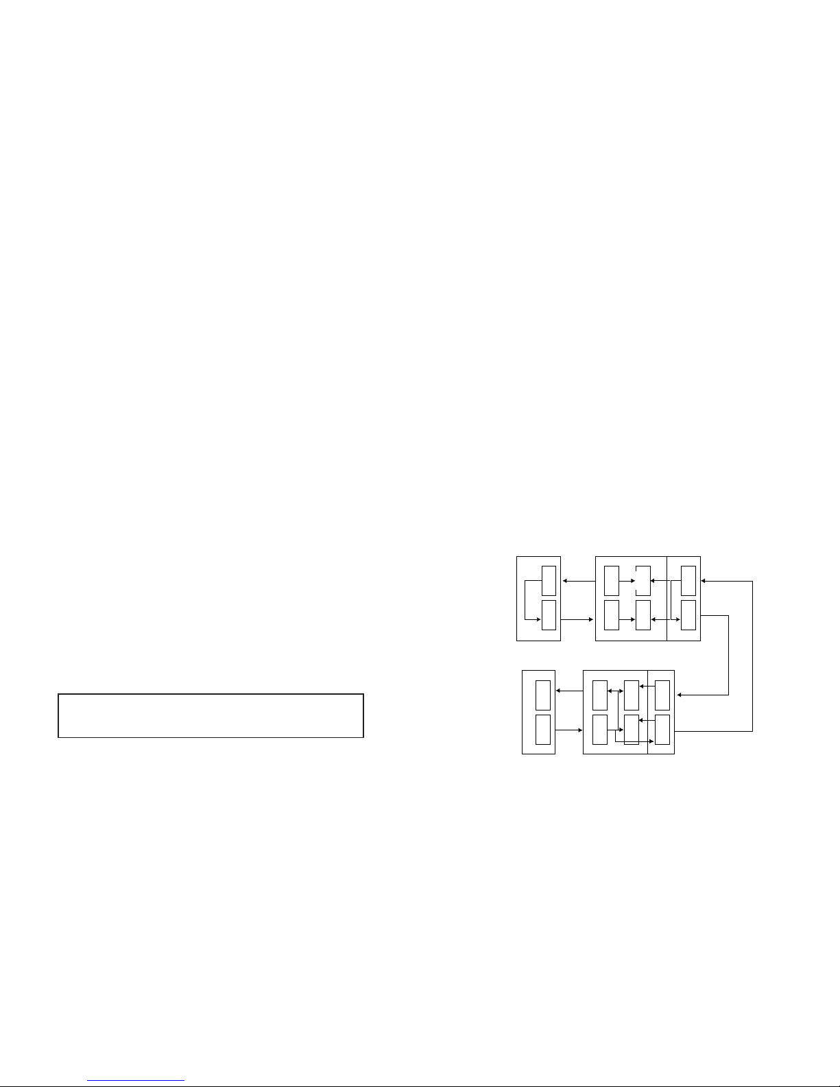
Timing of Application 2: Network Replacement
The first modem uses an internal timing source and supplies the
timing for the entire system. The first G.703 recovers the timing and
clocks the data into the FIFO. The Tx of the first modem takes its
internal clock and sends it (TXCLK1) to the G.703 FIFO for data
(TXD1). The Rx of the second modem recovers the clock and presents a “jittery” clock and data to the second G.703’s transmitter. It has
to smooth the clock before it uses the clock to transmit.
The Rx of the second G.703 recovers the timing and clocks the
data into a FIFO. The Tx of the second modem sends the second
modem’s recovered clock (TXCLK1) to the G.703 FIFO for data
(TXD1). The Rx of the first modem uses its internal clock (RXCLK1) to
send data (RXD1) into the FIFO. The Tx of the first G.703 smooths the
first modem’s recovered timing and sends it to the FIFO for data.
Both G.703 interfaces are in Modem Timed mode. See Figure 2
above.
2.4 TIMING MODE SELECTIONS
Based on the timing arrangements and clock sources mentioned
above, there are two timing modes in which the interface can work.
These two modes select the clock sources mentioned above and
determine which clock gets smoothed.
Network Timed: This sets the interface to pass the
smoothed recovered timing to the modem
as XCLK1, with the Rx data as TXD1, and
also to the G.703 Tx side.
Modem Timed: This sets the interface to use the modem’s
Tx timing (recovered or internal source) to
send the Rx data (as TXD1) to the modem
and to smooth the modem’s recovered timing for transmitting on the G.703 Tx side.
In both cases, the transmitter uses the smoothed clock.
2.5 CLEAR CHANNEL MODE
The Model IM1/F-128K provides one data mode in which the interface passes data and timing, as described below:
Clear Channel Mode: Data is passed at a128K rate. This does
not preserve the byte integrity associated
with Octet timing. Instead, an Octet timing
alarm (on or off) is passed over the modem
similar to the way signaling leads are
passed.
Figure 2. Network Replacement Configuration
RX
TX
CSU
DTE
G.703
RX
RX
RX
RX
RX
2 or 4 Wire
TX
G.703 INTF-
MODEM
TIMED MODE
SECOND MODEM
FIFO
TX
SMOOTHED
TX
TX
TX
FIFO
FIFO
G.703
FIFO
HOST
MODEM -
RECOVERED
TIMING
FIRST MODEM
HOST
MODEM INTERNAL
TIMING
G.703 INTF-
MODEM
TIMED MODE
CSU
DTE
G.703 TX
SMOOTHS
RX MODEM
CLOCK
G.703 TX SMOOTHS
RX MODEM CLOCK
Page 5

7 8
3.0 CONFIGURATION
The Model IM1/F-128K is equipped with four DIP switches that allow configuration of the unit to match your application. These DIP switches are located
on the top side of the module. Refer to Figure 3 below for a description of the
DIP switches location on the module and a summary table detailing their settings.
3.1 Switch Set S1
The following table defines the possible configurations of the
IM1/F-128K using the configuration DIP switch, S1.Factory defaults
are in bold-face.
Switch
On Off
S1-1 Modem Timed Network Timed
S1-2 Not Used Not Used
S1-3 Clear Channel Mode Not Used
S1-4 Normal Operation Reserved for Factory
Use
4.0 INSTALLATION
Once the Model IM1/F-128K is properly configured, it is ready to install
into Patton Model 1090, 1092, 1094A and 1095.. This section tells you how to
properly connect the Model IM1/F-128K.
4.1 HOW TO INSTALL THE NEW QUICKCONNECTTMMODULE
The Quick connect module has a 50 pin card edge connector on one side
and an RJ-45 connector on the other
The following instructions show you
how a QuickConnect
TM
module plugs into the back of a Patton
Electronics Model 1090,1092, 1094A or 1095.
1. Make sure the host modem power switch is off. Leave the
power cord plugged into a grounded outlet to keep the unit
grounded. The telephone cord must remain disconnected
from the telecommunications system until the card has been
installed within the host.
2. Hold the module with the faceplate toward you and align the
module with the guide slots in the rear panel of the Model
1090,1092, 1094A or 1095.
3. While keeping the module’s faceplate parallel with the Modem
rear panel, slide the module straight in so that the card edge
contacts line up with the socket inside the chassis.Refer to
Figure 4 below.
Figure 3: Top Side of IM 1/F-128K, Dip Switch Location
4 3 2 1
On
Off
0 OFF
1 ON
Line
Interface Port
Figure 4. Installation of Model IM 1/F-128K Plug-in Serial Interface Module
NOTE: Switches S1-3 and S1-4 must be ON.
Safety Precautions
The telecommunications interface is intended to be connected
to Telecommunication Network Voltage (TNV) circuits that may
carry dangerous voltages. Therefore, for safety measures, it is
imperative that the following instructions be followed exactly.
Page 6

9 10
4. With the card edge contacts aligned with the socket, firmly
seat the module by using your thumbs to apply pressure
directly to the right and left edges of the module faceplate.
Applying moderate and even pressure should be sufficient to
seat the module. You should hear it click into place.
5. To secure the module in place, push the thumbscrews into the
chassis and turn the screws clockwise to tighten.
6. The enclosure provides the necessary protection of the
operator, and the power can now be applied to the modem
and then the network connected.
4.2 REMOVING THE EXISTING QUICKCONNECTTMMODULE
1. Turn off the modem power switch. Leave the power cord
plugged into a grounded outlet to keep the unit ground. The
line connection should also be disconnected before
removing the module.
2. Loosen the two thumbscrews on the module by turning them
counterclockwise.
3. Grasp the thumbscrews and gently pull the module from the
unit. Apply equal force to the thumbscrews to keep the
module straight as you remove it.
4.3 CONNECTION TO THE TWISTED PAIR INTERFACE
The Model IM1/F-128K supports communication between itself and a
G.703 PCM network at distances up to 3,000 feet (914m) using 24 AWG twisted pair cable.
To function properly, the Model IM1/F-128K requires two twisted pairs of
metallic wire. These twisted pairs must be unconditioned, dry metallic wire,
between 22 and 26 AWG (0.4mm to 0.6mm diameter solid conductors). Higher
gauge wire may limit distance. Flat modular telephone type cable is not
acceptable.
The RJ-45 connector on the Model IM1/F-128K twisted pair interface is
pre-wired according to the signal/pin relationships shown in Figure 5 below.
1 (RX Tip)
2 (RX Ring)
3 (N/C)
4 (TX Ring)
5 (TX Tip)
6 (N/C)
7 (N/C)
8 (N/C)
1
2
3
4
5
6
7
8
Pin Signal Name Direction Function
(In reference to IM)
1 RD(T) IN Receive data in (tip)
2 RD(R) IN Receive data in (ring)
3 Not used
4 TD(R) OUT Transmit data out (ring)
5 TD(T) OUT Transmit data out (tip)
6 Not used
7 Not used
8 Not used
Figure 5. Model IM 1/F-128K Twisted Pair Interface Signal/Pin Relationship
NOTE: The card edge connector should meet the socket when
it is almost all the way into the chassis. If you encounter a lot of
resistance, remove the module and repeat Steps 2 and 3.
Safety Precautions
If you want to open the host equipment, the network connection must be disconnected prior to accessing any internal parts
that may carry TNV and the following instructions should be followed exactly.
IMPORTANT
Connection of the Patton G.703 IM to a
CSU DTE
requires a crossover
twisted pair cable. Connection of the Patton G.703 interface module to a
PCM network
requires a straight through pair cable.
Page 7

11
APPENDIX A
PATTON MODEL IM1/F-128K SPECIFICATIONS
Applications: 128K G.703 co-directional PCM network
extension or network replacement
Connector: Symmetrically balanced pair, 4 wire RJ-45
female
Interface: Entire module plugs into Patton Electronics
Model 1090, 1092, 1094A and 1095.
Operating Supports clear channel mode
Modes/Speed: Co-directional timing, Rx recovered:
128Kbits + 500ppm
Line Coding: AMI with block violation for octet timing
Timing Modes: Supports network timing mode or modem
timing mode
Transmit Level: 2.0V differential, into 100 Ohms, nominal
Load Impedance: 120 Ohms
Input Signal Level: 0 to -10dB
Jitter Performance: CTR 14, G.823. <0.05UI jitter for network
extension applications
Isolation: 2000 VRMS isolation, transformer coupled
PC Board 2.950” X 3.200”, QuickConnect
TM
Interface
Dimensions: Module size
Compliance: FCC Class A
EN 55022 Class A
EN 50082-1, Susceptibility
Copyright © 1999
Patton Electronics Company
All Rights Reserved
 Loading...