

Page 1

G.SHDSL NTU
User Manual
Version 0.03
Page 2

G.SHDSL NTU User Manual V0.03 1
Tables of Contents
1 INTRODUCTION ................................................................................................................................................ 4
1.1 M
ODELS
............................................................................................................................................................. 4
1.1.1 E1 interface model ................................................................................................................................... 4
1.1.2 Serial (V.35) interface model ................................................................................................................... 4
1.1.3 Ethernet interface model ......................................................................................................................... 4
1.1.4 Multi-interfaces model ............................................................................................................................ 4
1.2 F
EATURES
........................................................................................................................................................... 5
1.3 S
PECIFICATION
..................................................................................................................................................... 5
1.4 A
PPLICATIONS
...................................................................................................................................................... 8
2 GETTING TO KNOW ABOUT THE SHDSL NTU ..................................................................................................... 9
2.1 F
RONT PANEL
...................................................................................................................................................... 9
2.1.1 E1 interface model ................................................................................................................................... 9
2.1.2 Serial interface model .............................................................................................................................. 9
2.1.3 Ethernet interface model ......................................................................................................................... 9
2.1.4 Multi-interfaces model .......................................................................................................................... 10
2.2 R
EAR PANEL
...................................................................................................................................................... 12
2.2.1 E1 Interface Model ................................................................................................................................. 12
2.2.2 Serial (V.35) Interface Model ................................................................................................................. 13
2.2.3 Ethernet Interface Model ....................................................................................................................... 14
2.2.4 Multi-interfaces Model .......................................................................................................................... 15
2.3 I
NSTALLATION
.................................................................................................................................................... 16
2.3.1 For E1 Interface ...................................................................................................................................... 17
2.3.2 For Serial Interface ................................................................................................................................. 18
2.3.3 For Ethernet Interface ............................................................................................................................ 19
3 CONFIGURATION WITH KEYPAD AND LCD ...................................................................................................... 21
3.1 K
EY PADS
.......................................................................................................................................................... 21
3.2 M
AIN MENU TREE
.............................................................................................................................................. 22
3.3 M
ENU TREE FOR
[SHOW STATUS] ...................................................................................................................... 24
3.4 M
ENU TREE FOR
[SHOW STATISTICS] ................................................................................................................. 28
3.5 M
ENU TREE FOR
[SYSTEM SETUP] ...................................................................................................................... 31
3.5.1 Sub-Menu tree for SETUP E1 Interface .................................................................................................. 35
3.5.2 Sub-Menu tree for SETUP SERIES Interface ............................................................................................ 39
3.5.3 Sub-Menu tree for SETUP Ethernet Interface ........................................................................................ 42
3.5.4 Application of Multi-interfaces .............................................................................................................. 43
3.6 M
ENU TREE FOR
[REBOOT SYSTEM] ................................................................................................................... 49
3.7 M
ENU TREE FOR
[SYSTEM DISGNOSTIC] ............................................................................................................ 50
3.7.1 Loopback Test ........................................................................................................................................ 52
Page 3

G.SHDSL NTU User Manual V0.03 2
3.7.2
BER Test ................................................................................................................................................. 55
3.8 P
ARAMETERS TABLE
............................................................................................................................................ 56
3.8.1 E1 Interface Model ................................................................................................................................. 56
3.8.2 Serial Interface Model ............................................................................................................................ 56
3.8.3 Ethernet Interface model ....................................................................................................................... 57
3.8.4 Multi-interface model--E1 Interface ...................................................................................................... 57
3.8.5 Multi-interface model--Serial Interface ................................................................................................. 58
3.8.6 Multi-interface model--Ethernet Interface ............................................................................................ 58
3.8.7 Multi-interface model--E1+Serial Interface ........................................................................................... 59
3.8.8 Multi-interface model--E1+Ethernet Interface ...................................................................................... 60
4 CONFIGURATION WITH CONSOLE PORT ......................................................................................................... 61
4.1 L
OGIN PROCEDURE
............................................................................................................................................. 61
4.2 W
INDOW STRUCTURE
.......................................................................................................................................... 63
4.3 M
ENU COMMANDS
............................................................................................................................................ 64
4.4 M
AIN MENU SUMMARY
...................................................................................................................................... 65
4.5 [S
ETUP] CONFIGURATION
..................................................................................................................................... 66
4.5.1 Configure Interface ................................................................................................................................ 70
4.5.2 Configure SHDSL parameters ................................................................................................................. 72
4.5.3 Configure E1 parameters ....................................................................................................................... 78
4.5.4 Configure Serial parameters .................................................................................................................. 86
4.5.5 Configure Ethernet parameters ............................................................................................................. 94
4.5.6 Enable and Disable Remote configuration ............................................................................................. 98
4.5.7 Restore factory default setting .............................................................................................................. 99
4.6 [S
TATUS] VIEW THE SYSTEM STATUS
..................................................................................................................... 101
4.6.1 Show SHDSL Status .............................................................................................................................. 102
4.6.2 Show Interface Status .......................................................................................................................... 104
4.6.3 Show Current Performance .................................................................................................................. 105
4.6.4 View the Local and remote Statistics ................................................................................................... 106
4.6.5 Clear Channel Statistics........................................................................................................................ 111
4.7 [S
HOW] VIEW SYSTEM CONFIGURATION
............................................................................................................... 112
4.7.1 Show general Interface ........................................................................................................................ 112
4.7.2 Show configuration in listing format ................................................................................................... 114
4.7.3 Show configuration in command script ............................................................................................... 117
4.8 [R
EBOOT] REBOOT THE SYSTEM
........................................................................................................................... 120
4.9 [D
IAG] DIAGNOSTIC – LOOPBACK AND
BER T
EST
................................................................................................... 121
4.9.1 Loopback test ....................................................................................................................................... 122
4.9.2 BER Test ............................................................................................................................................... 123
4.10 [U
PGRADE] FIRMWARE UPGRADE
........................................................................................................................ 125
4.11 [E
XIT] EXIT THE SYSTEM
..................................................................................................................................... 130
5 APPENDIX ..................................................................................................................................................... 132
Page 4

G.SHDSL NTU User Manual V0.03 3
5.1
A
BBREVIATION
................................................................................................................................................. 132
5.2 S
ERIAL INTERFACE PIN ASSIGNMENTS
................................................................................................................... 135
5.3 V.35 DB25(M)
TO
M.34(F)
ADAPTOR CABLE
...................................................................................................... 137
5.4 X.21 DB25(M)
TO
DB15(F)
ADAPTOR CABLE
...................................................................................................... 139
5.5 C
ONSOLE CABLE
............................................................................................................................................... 141
5.6 E1 B
ALANCE CABLE
........................................................................................................................................... 143
5.7 E1 U
NBALANCE CABLE
...................................................................................................................................... 144
5.8 E
THERNET CABLE
.............................................................................................................................................. 145
5.9 DSL C
ABLE
...................................................................................................................................................... 146
5.10 P
OWER CORD
.................................................................................................................................................. 147
5.11 I
LLUSTRATION OF LOOPBACK CONNECTION DEVICE
(E1) ........................................................................................... 148
5.12 I
LLUSTRATION OF LOOPBACK CONNECTION DEVICE (SERIAL
) ...................................................................................... 149
Page 5
G.SHDSL NTU User Manual V0.03 4
1 Introduction
1.1 Models
The G.SHDSL NTU offers three different interfaces (E1, Serial and Ethernet) connected customers to high-speed TDM
services .This series have four models on the following:-
1.1.1 E1 interface model
It offers two different ways have connected customers to high-speed TDM services with two G.703 E1 interfaces
(Balance 120Ω RJ45 jack and Unbalance 75Ω dual BNCs). The G.703 interface can carry 64kbps to 2.048Mbps.
1.1.2 Serial (V.35) interface model
It offers customers premises has high-speed TDM services with a DB25 interface. The industry standard DB25
interface can be configured as a V.35/RS530 or V.36/X.21 connection. The DB25 connection can transfers data up to
2.304Mbps.
1.1.3 Ethernet interface model
It offers customers premises has high-speed TDM services with a LAN interface. The industry standard LAN interface
can detect a 10Mbps or 100Mbps connection automatically.
1.1.4 Multi-interfaces model
It offers customers premises have three types interface: E1 interface (balanced 120Ω RJ48C jack and unbalanced
75Ω dual BNCs), V.35 interface (DB25 female connector) and Ethernet interface (RJ-45 connector). You can select
five type interfaces according to your application: (a) E1 interface only, (b) Series interface only, (c) Ethernet
interface only , (d) E1 and Serial interface come together and (e) E1 and Ethernet interface come together.
Page 6

G.SHDSL NTU User Manual V0.03 5
They can be configured and managed via EOC, or menu-driven VT100 compatible Asynchronous Terminal Interface,
either locally or remotely.
The G.SHDSL NTU is equipped with an auto rate capability that identifies the maximum line rate supported by the
copper loop. This powerful automatic configuration capability makes installation and service provisioning simple and
painless. Further flexibility is provided in the ability to manually set the maximum NTU speed at different levels for
different customer-tailored service offerings.
1.2 Features
Standard G.SHDSL (ITU G.991.2) supports improved reach/speed and greater interoperability
Fast and cost-effective provisioning of traditional frame relay (FR or T-HDLC) or TDM leased line services
User existing copper loop infrastructures
Can operate back to back connection
Efficient single wire pair usage
Up to 2.312Mbps symmetric service bit rate
Auto rate installation maximizes data rate based on loop conditions
Auto configuration wetting current to protect SHDSL line
Local management interface with LCD display
Remote line loopback
SHDSL Line performance monitoring (Data Rate and SNR)
Raw and per time interval statistics
Bandwidth guaranteed transmission equipment
Remote firmware upgrade
1.3 Specification
WAN Interface
• Line Rate: SHDSL per G.991.2
• Coding: trellis coded pulse amplitude modulation (TCPAM-16)
• Support: Annex A(ANSI) and Annex B(ETSI)
• Payload rates: 64kbps to 2.304Mbps (N x 64kbps N=1 to 36) for Serial and Ethernet interface
64kbps to 2.048Mbps (N x 64kbps N=1 to 32) for E1 interface
• Connection: RJ-45 jack (2-wire or 4-wire)
• Impedance: 135 ohms
G.703 Interface (as E1)
• Connection: RJ-45 for balanced 120Ω E1 cable
Page 7

G.SHDSL NTU User Manual V0.03 6
• Connection: BNC for unbalanced 75Ω E1 cable
• Line Rate: 2048KHz +/- 50ppm
• Framing: PCM30/30C/31/31C and Unframed
• Data Rate: 64Kbps to 2.048Mbps (Nx64Kbps , N=1 to 32)
• Operation: Full E1 and Fractional E1
SERIAL Interface (as V.35)
• Connection:DB-25(F)
• Payload rates: Up to 2.304Mbps (N=1 to 36)
• Support RS-530, V.35 or V.36/X.21
LAN Interface (as Ethernet)
• Single Ethernet Interface
• 10/100Mpbs Half/Full Duplex, Auto-sensing, Auto-Crossover
• Up to 2048 MAC address learning
DSL Timing
• Internal
• From E1 Recovery (as E1)
• From DTE (as V.35 and Ethernet)
Performance Monitoring
• ES, SES, UAS, LOSW, Alarms, Errors
Loopback Tests (for E1 and V.35 interface only)
• Digital Local Loopback
• Digital Loopback
• Remote Line Loopback
• Remote Payload Loopback
• Far-end Line Loopback
• Far-end Payload Loopback
• V.54(For V.35 interface only)
• Build-in 2047 bit (2
11
-1) BER tester
Management
• Configuration with keypads and LCD display
• Console port (RJ45)
• Support firmware upgradeable
Physical/Electrical
• Dimensions: 19.8 x 4.6 x 16.8 cm
Page 8

G.SHDSL NTU User Manual V0.03 7
• Input: For AC power input version 90~240VAC with 50~60Hz
For DC Power input version -48VDC
• Power Consumption: 10W Max
• Operation temperature: 0 to 50°C
• Humidity: Up to 95% (non-condensing)
• External screw for frame grounding
Page 9

G.SHDSL NTU User Manual V0.03 8
1.4 Applications
Page 10
G.SHDSL NTU User Manual V0.03 9
2 Getting to know about the SHDSL NTU
This chapter shows the front and rear panel and how to install the hardware.
2.1 Front Panel
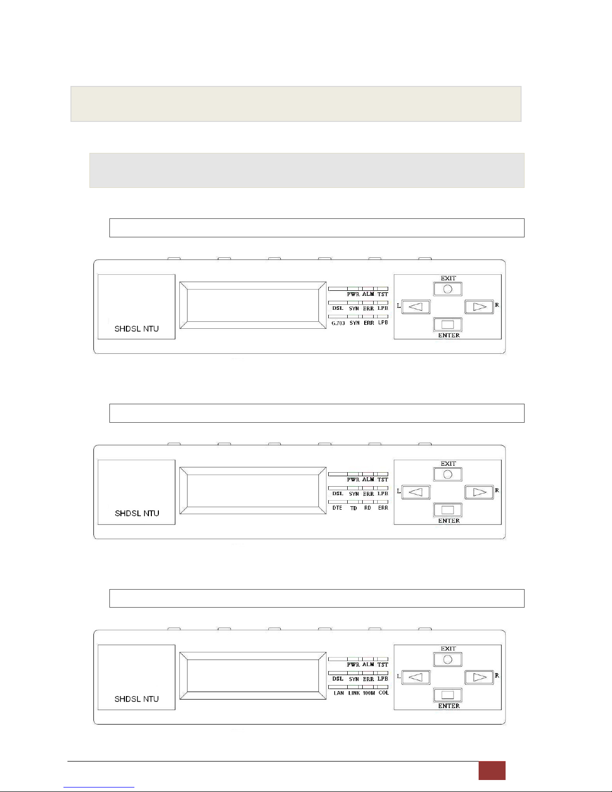
2.1.1 E1 interface model
2.1.2 Serial interface model
2.1.3 Ethernet interface model
Page 11
G.SHDSL NTU User Manual V0.03 10
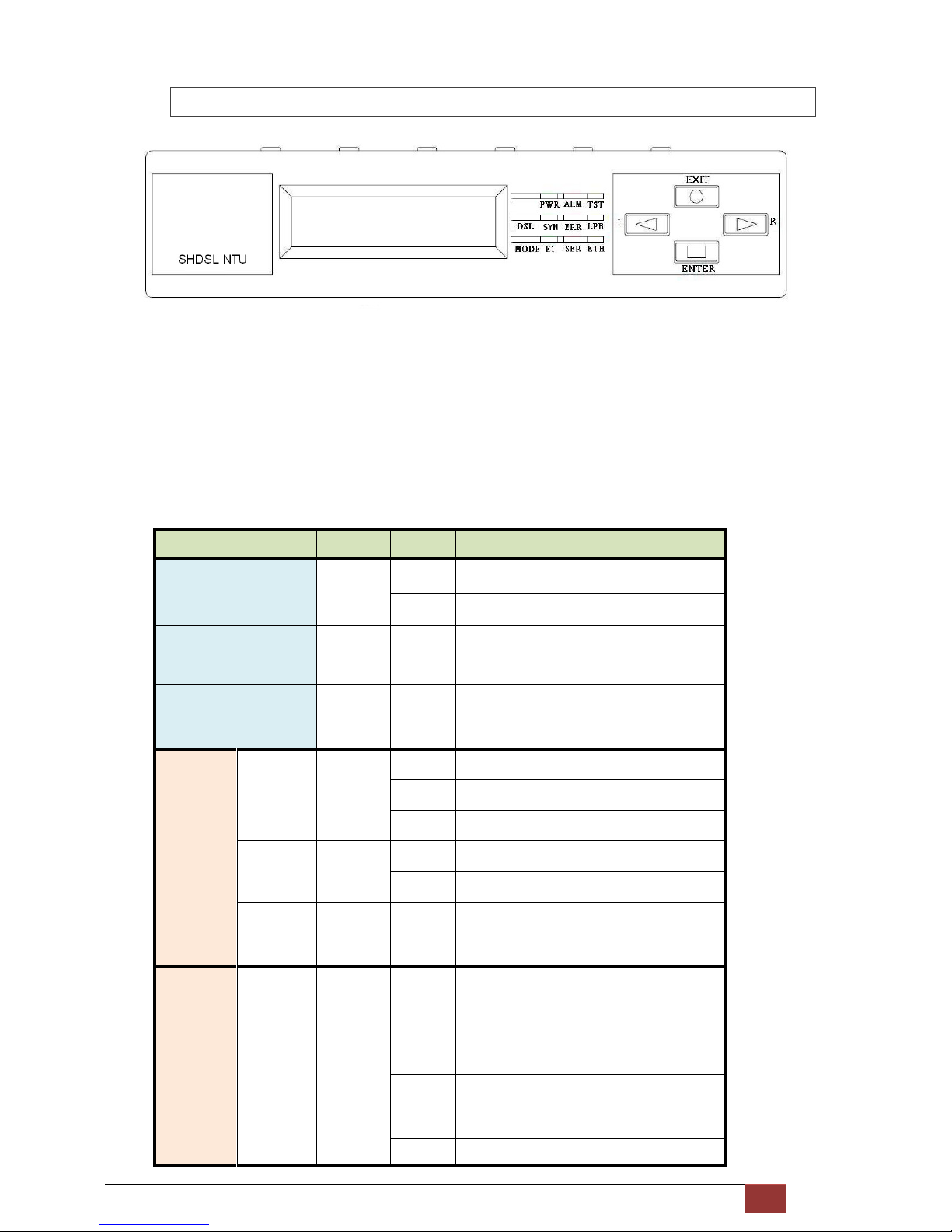
2.1.4 Multi-interfaces model
Front panel can be separated into three parts: LCD display, LED indicator and Keypads.
The LCD display can show the status and configuration of device. The local management interface will be done by
keypads with this LCD display.
The purpose of key pads is to configure the setting or selecting of function on this SHDSL NTU.
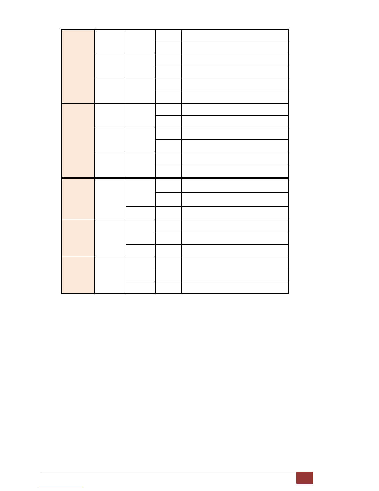
The following table describes the LEDs’ function of device.
LED Color Action Description
PWR Green
On Power is on.
Off Power is off.
ALM Red
On System loss.
Off System is working nomarally.
TST Yellow
On System is testing for connection.
Off System is working nomarlly.
DSL
SYN Green
On SHDSL line is connected.
Blink Data transmit in SHDSL line.
Off SHDSL line is dropped.
ERR Red
Blink Error second occurs.
Off No error second.
LPB Yellow
On Loopback is on.
Off Loopback is off.
E1
SYN Green
On E1 line is connected.
Off E1 line is dropped.
ERR Red
Blink There are error seconds.
Off There is not any error second.
LPB Yellow
On Loopback is on.
Off Loopback is off.
Page 12
G.SHDSL NTU User Manual V0.03 11
Serial
TD Green
On Data transmit in V.35.
Off No data transmit in V.35.
RD Green
On Data receive in V.35.
Off No data reveive in V.35.
ERR Red
Blink Error second occurs.
Off No error second.
ETH
LINK Green
On Data transmit in Ethernet.
Off No data transmit in Ethernet.
100M Green
On Data receive in 100M.
Off No data receive in 100M.
COL Red
Blink Error collision occurs.
Off No error collision.
E1
Green
Blink E1 Data tramsmit and receive
On E1 cable cable connected
Red On No E1 cable connected
Mode
SER
Green
Blink Serial Data tramsmit and receive
On DTE Connected
Red On DTE Disconnect
ETH
Green
Blink Ethernet Data tramsmit and receive
On Ethernet cable connected
Red On No Ethernet cable connected
Page 13
G.SHDSL NTU User Manual V0.03 12
2.2 Rear Panel
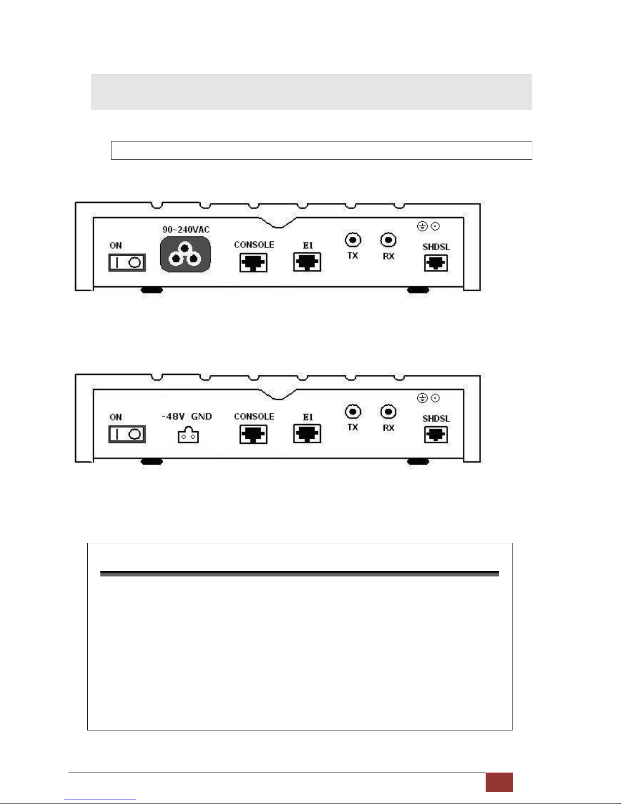
2.2.1 E1 Interface Model
AC power input version
The rear panel of this model is including power switch, AC power socket, RJ-45 console, G.703 RJ-48C jack or BNC
jack for transmitting and receiving and RJ-45 for SHDSL from left to right.
DC power input version
The rear panel of this model is including power switch, DC power socket, RJ-45 console, G.703 RJ-48C jack or BNC
jack for transmitting and receiving and RJ-45 for SHDSL from left to right.
Connector Description
ON
Power switch. Press 1 for turn on and press 0 for off
90~240V AC
IEC-320 C6 AC input connector. It has power adapting function from 90V to
240V
-48V GND
DC power input connector (-48V)
CONSOLE
RJ-45 for system configuration and maintenance
G.703
RJ-48C for 1
20Ω E1 connection with PABX (Private Automatic Branch Exchange)
or E1 Router
TX
BNC for 75Ω E1 transmitting
RX
BNC for 75Ω E1 receiving
SHDSL
RJ-45 for DSL connection
Page 14
G.SHDSL NTU User Manual V0.03 13
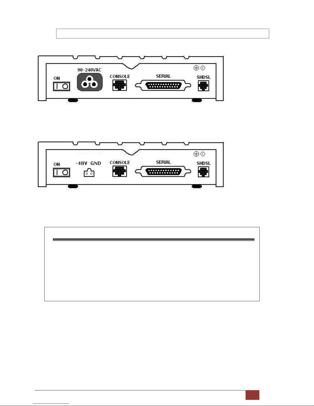
2.2.2 Serial (V.35) Interface Model
AC power input version
The rear panel of this model is including power switch, AC power socket, RJ-45 for console cable, DB-25(Female) for
serial and RJ-45 for SHDSL from left to right.
DC power input version
The rear panel of this model is including power switch, DC power socket, RJ-45 for console cable, DB-25(Female) for
serial and RJ-45 for SHDSL from left to right.
Connector Description
ON
Power switch. Press 1 for turn on and press 0 for off.
90~240V AC
IEC-320 C6 AC input connector. It has power adapting function from 90V to
240V
-48V GND
DC power input connector (-48V)
CONSOLE
RJ-45 for system configuration and maintenance
SERIAL
DB-25(F) for RS-530 and V.35 or X.21(with adaptor cable)
SHDSL
RJ-45 for DSL Connection
Page 15
G.SHDSL NTU User Manual V0.03 14
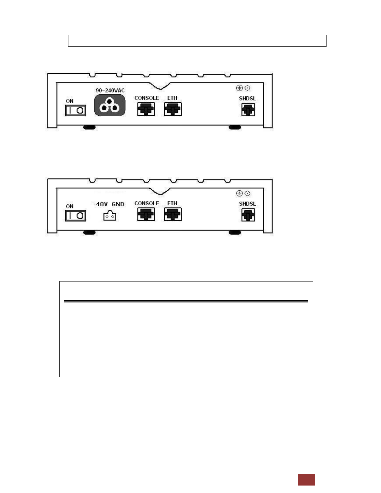
2.2.3 Ethernet Interface Model
AC power input version
The rear panel of this model is including power switch, AC power socket, RJ-45 for console cable, LAN for Ethernet
cable and RJ-45 for SHDSL from left to right.
DC power input version
The rear panel of this model is including power switch, DC power socket, RJ-45 for console cable, LAN for Ethernet
cable and RJ-45 for SHDSL from left to right.
Connector Description
ON
Power switch. Press 1 for turn on and press 0 for turn off.
90~240V AC
IEC-320 C6 AC input connector. It has power adapting function from 90V to
240V.
-48V GND
DC power input connector (-48V)
CONSOLE
RJ-45 for system configuration and maintenance.
ETH
RJ-45 LAN port for Ethernet cable
SHDSL
RJ-45 for DSL Connection
Page 16
G.SHDSL NTU User Manual V0.03 15
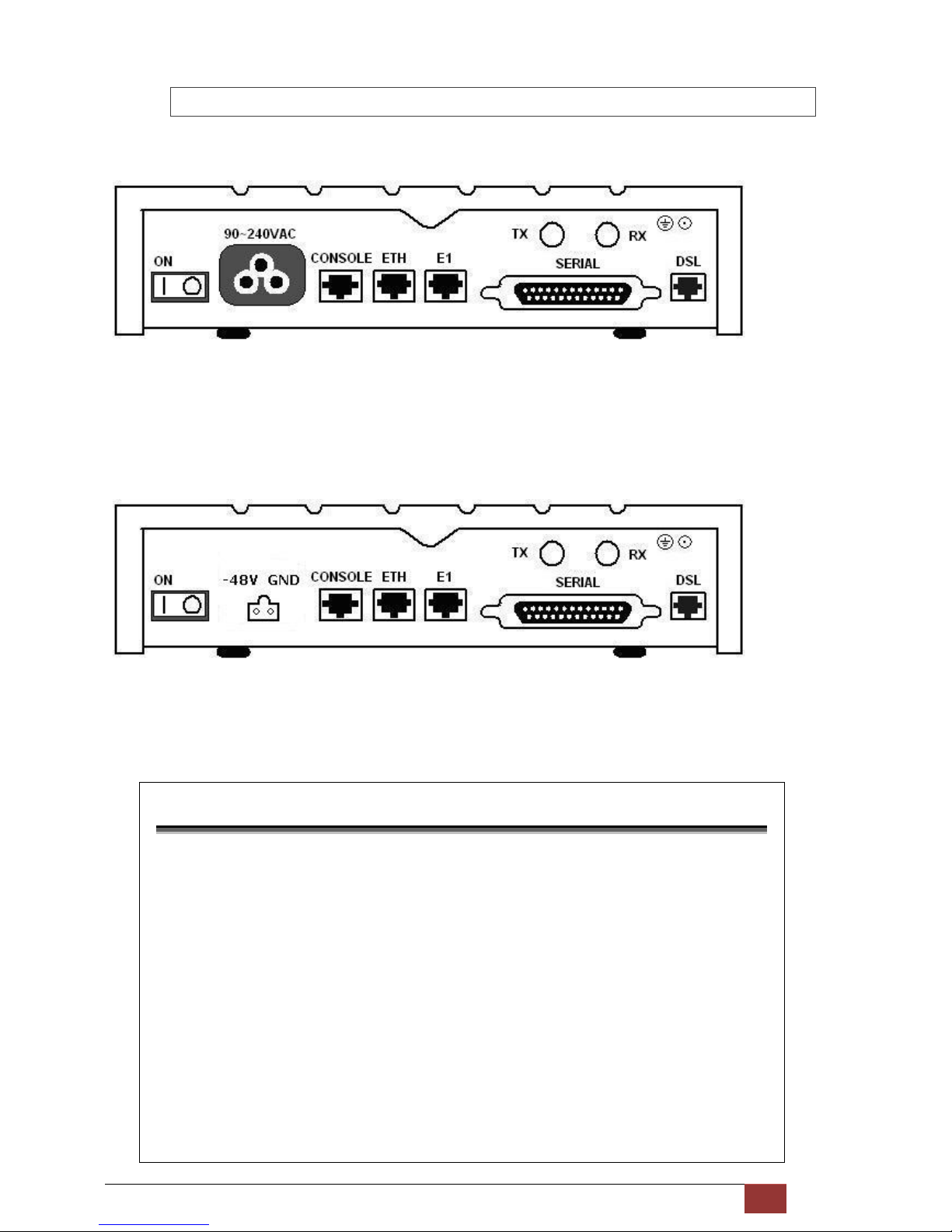
2.2.4 Multi-interfaces Model
DC power input version
The rear panel of this model is including power switch, AC power socket, RJ-45 for console cable, LAN for Ethernet
cable, G.703 RJ-48C or BNC jacks for transmitting and receiving, DB-25(Female) for serial and RJ-45 for SHDSL from
left to right.
DC power input version
The rear panel of this model is including power switch, DC power socket, RJ-45 for console cable, LAN for Ethernet
cable, G.703 RJ-48C or BNC jacks for transmitting and receiving, DB-25(Female) for serial and RJ-45 for SHDSL from
left to right.
Connector Description
ON Power switch. Press 1 for turn on and press 0 for off
90~240V AC
IEC-320 C6 AC input connector. It has power adapting function from 90V to
240V
-48V GND
DC power input connector (-48V)
CONSOLE
RJ-45 for system configuration and maintenance
ETH
RJ-45 LAN port for Ethernet cable
E1
RJ-48C
for 120Ω E1 connection with PABX (Private Automatic Branch Exchange)
or E1 Router
SERIAL
DB-25(F) for RS-530 and V.35 or X.21(with adaptor cable)
TX
BNC for 75Ω E1 transmitting
RX BNC for 75Ω E1 receiving
DSL
RJ-45 for DSL connection
Page 17
G.SHDSL NTU User Manual V0.03 16
2.3 Installation
Note: To avoid possible damage to this router, do not turn on the product before hardware installation.
Plug the power cord in the power socket.
Plug the console port in console if you want to configure the NTU with VT100 program of NB or PC.
Plug the E1 cable (Either 75Ω BNC cables or 120Ω cable) / SERIAL cable / Ethernet cable
Plug SHDSL cable
Power on
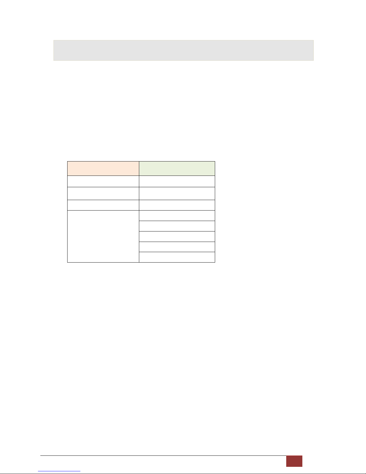
Model Interface modes support
E1 interface model E1 interface
V.35 interface model V.35 interface
Ethernet interface model Ethernet interface
Multi-interfaces model E1 interface
V.35 interface
Ethernet interface
E1+V.35 interface
E1+Ethernet interface
Only the Multi-interfaces model can support all five type interfaces.
Page 18
G.SHDSL NTU User Manual V0.03 17
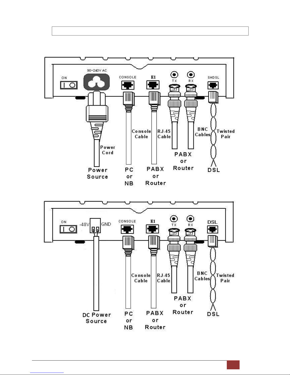
2.3.1 For E1 Interface
AC power input version
DC power input version
Page 19
G.SHDSL NTU User Manual V0.03 18
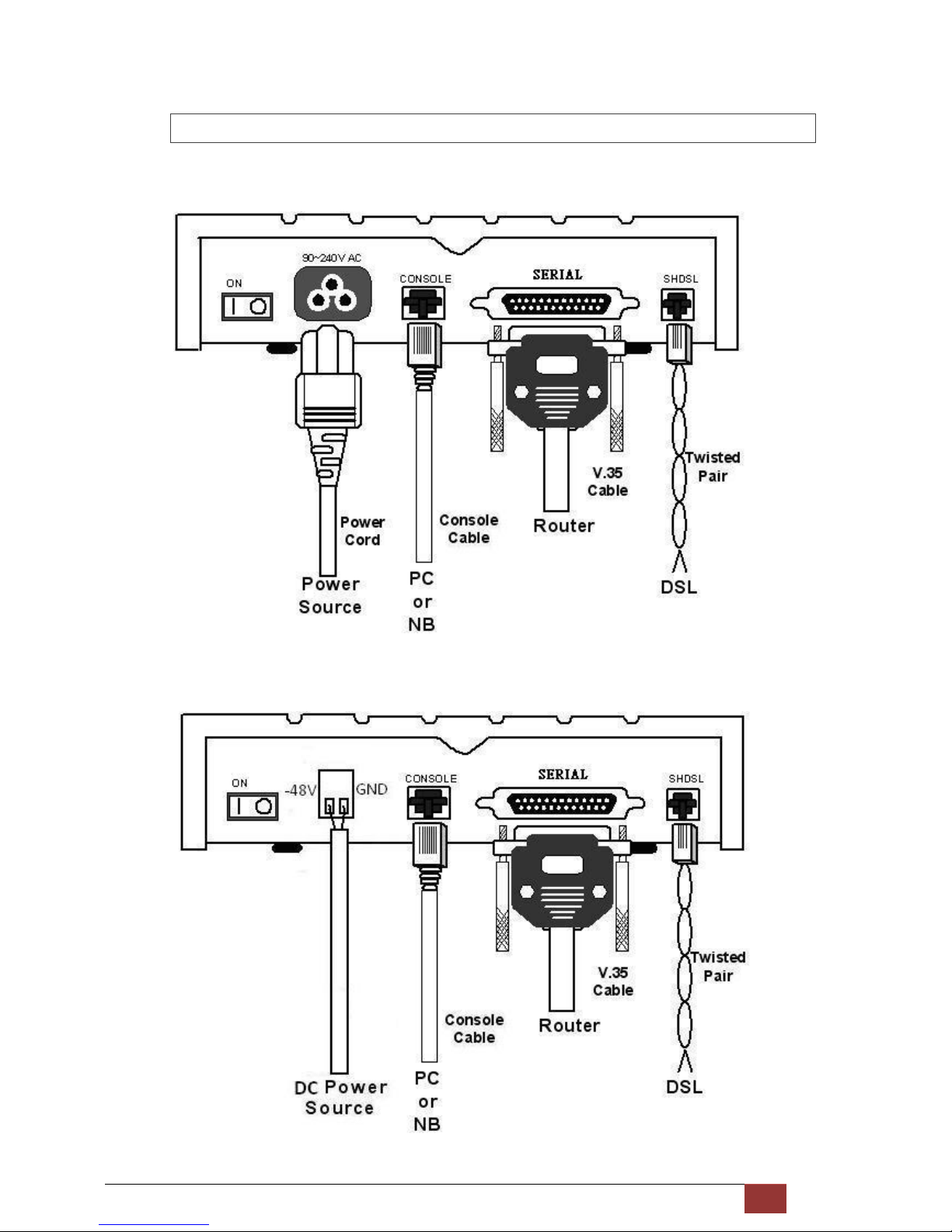
2.3.2 For Serial Interface
AC power input version
DC power input version
Page 20
G.SHDSL NTU User Manual V0.03 19
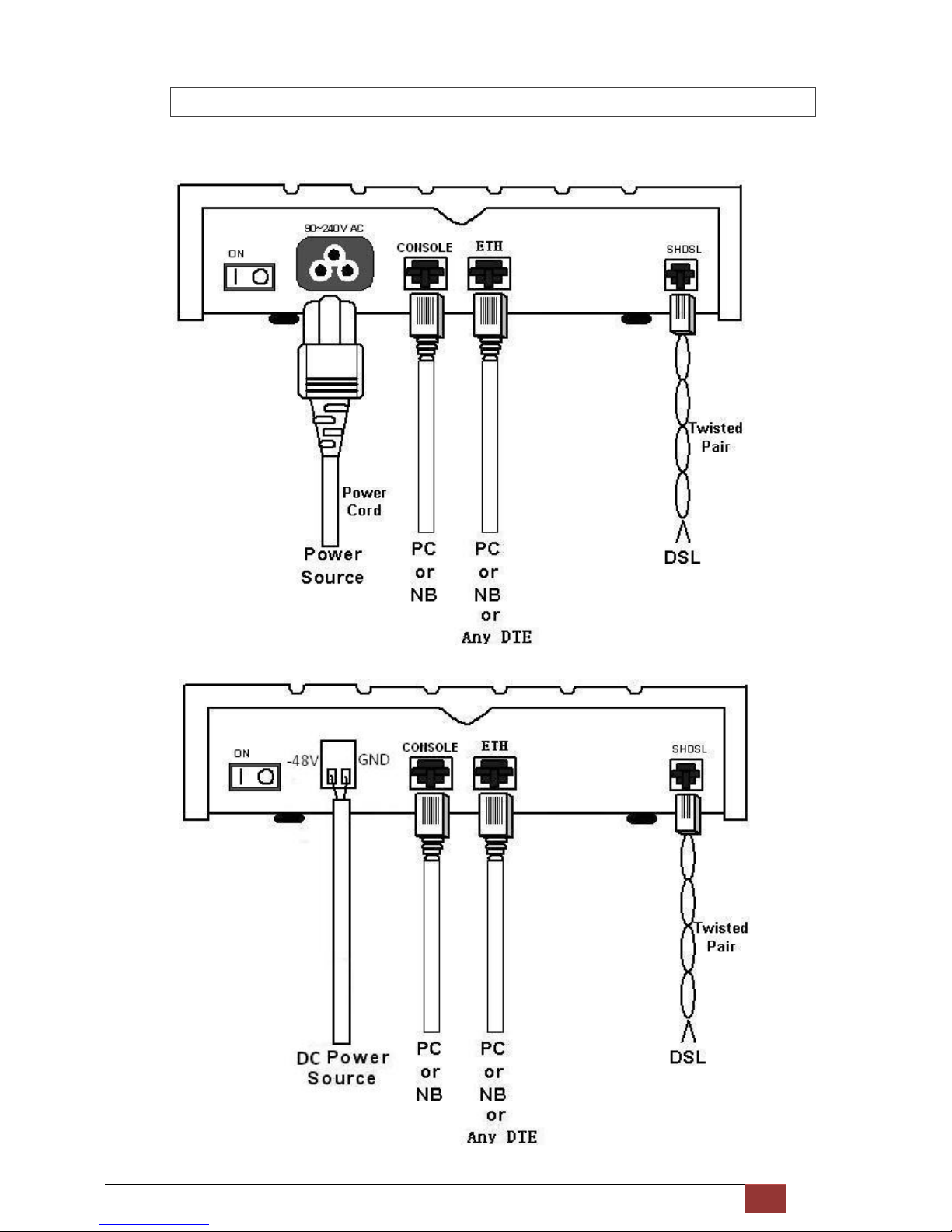
2.3.3 For Ethernet Interface
AC power input version
DC power input version
Page 21

G.SHDSL NTU User Manual V0.03 20
Protective earth:
The marked lug or terminal should be connected to the building protective earth bus.
The function of protective earth does not serve the purpose of providing protection against electrical shock, but
instead enhances surge suppression on the DSL lines for installations where suitable bonding facilities exist.
The connector type is M3 machine screw.
Wetting Current:
Wetting current, also known as loop sealing current, is a low-level DC current applied to a loop for the specific
purpose of maintaining cable splice integrity by preventing the build-up of oxidation. There has the ability to sink the
source wetting current.
!
Warning! High Voltage. Do not open the housing.
Page 22
G.SHDSL NTU User Manual V0.03 21
3 Configuration with Keypad and LCD
This chapter provides information about configuration on your G.SHDSL NTU via front panel LCD display and
keypads.
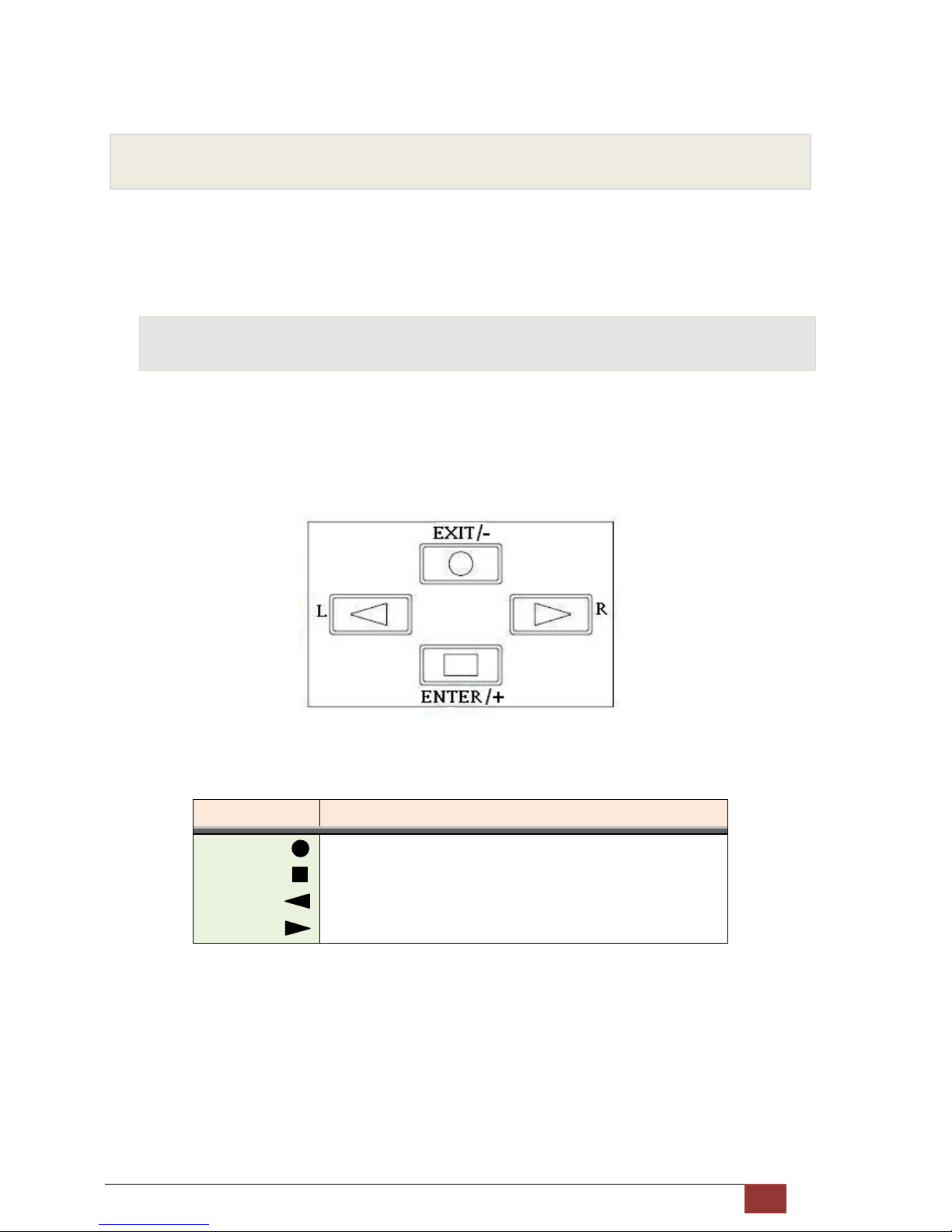
3.1 Key Pads
The G.SHDSL NTU is designed by user-friendly configuration and management can using keypads and LCD display on
front panel only without computer with VT100 terminal software.
Key Pad Description
Exit/- Return to previous configuration menu.
Enter/+ Skip to next configuration menu or configure this item.
L Select other parameter in the same level menu.
R
Select other parameter in the same level menu.
Page 23
G.SHDSL NTU User Manual V0.03 22
3.2 Main menu Tree
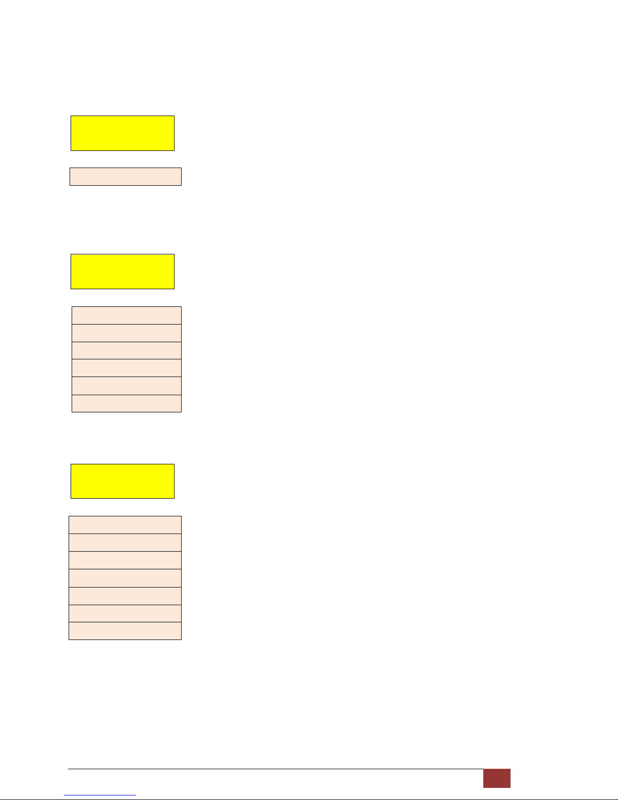
After turning on G.SHDSL NTU, the LCD display will prompt “SHDSL NTU” and their interface mode. Press Enter key
to enter. There will display some sub-menu of the following.
E1 interface mode:
SHDSL NTU
======E1======
SHOW
STATUS
SHOW
STATISTICS
SYSTEM
SETUP
REBOOT
SYSTEM
SYSTEM
DIAGNOSTIC
Serial interface mode:
SHDSL NTU
====SERIAL====
SHOW
STATUS
SHOW
STATISTICS
SYSTEM
SETUP
REBOOT
SYSTEM
SYSTEM
DIAGNOSTIC
Page 24
G.SHDSL NTU User Manual V0.03 23
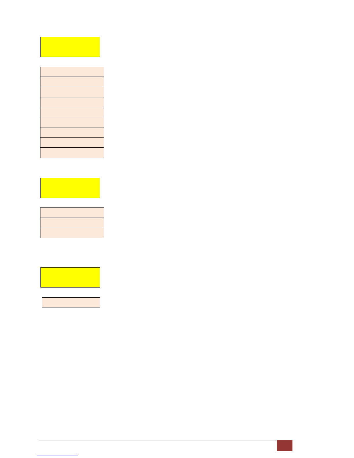
Ethernet interface mode:
SHDSL NTU
===ETHERNET===
SHOW
STATUS
SHOW
STATISTICS
SYSTEM
SETUP
REBOOT
SYSTEM
E1 and Serial interface mode:
SHDSL NTU
== E1 + SERIAL ==
SHOW
STATUS
SHOW
STATISTICS
SYSTEM
SETUP
REBOOT
SYSTEM
SYSTEM
DIAGNOSTIC
E1 and Ethernet interface mode:
SHDSL NTU
== E1 ETHERNET ==
SHOW
STATUS
SHOW
STATISTICS
Page 25
G.SHDSL NTU User Manual V0.03 24
SYSTEM
SETUP
REBOOT
SYSTEM
SYSTEM
DIAGNOSTIC
For more detail on those sub-menus, please refer to each chapter.
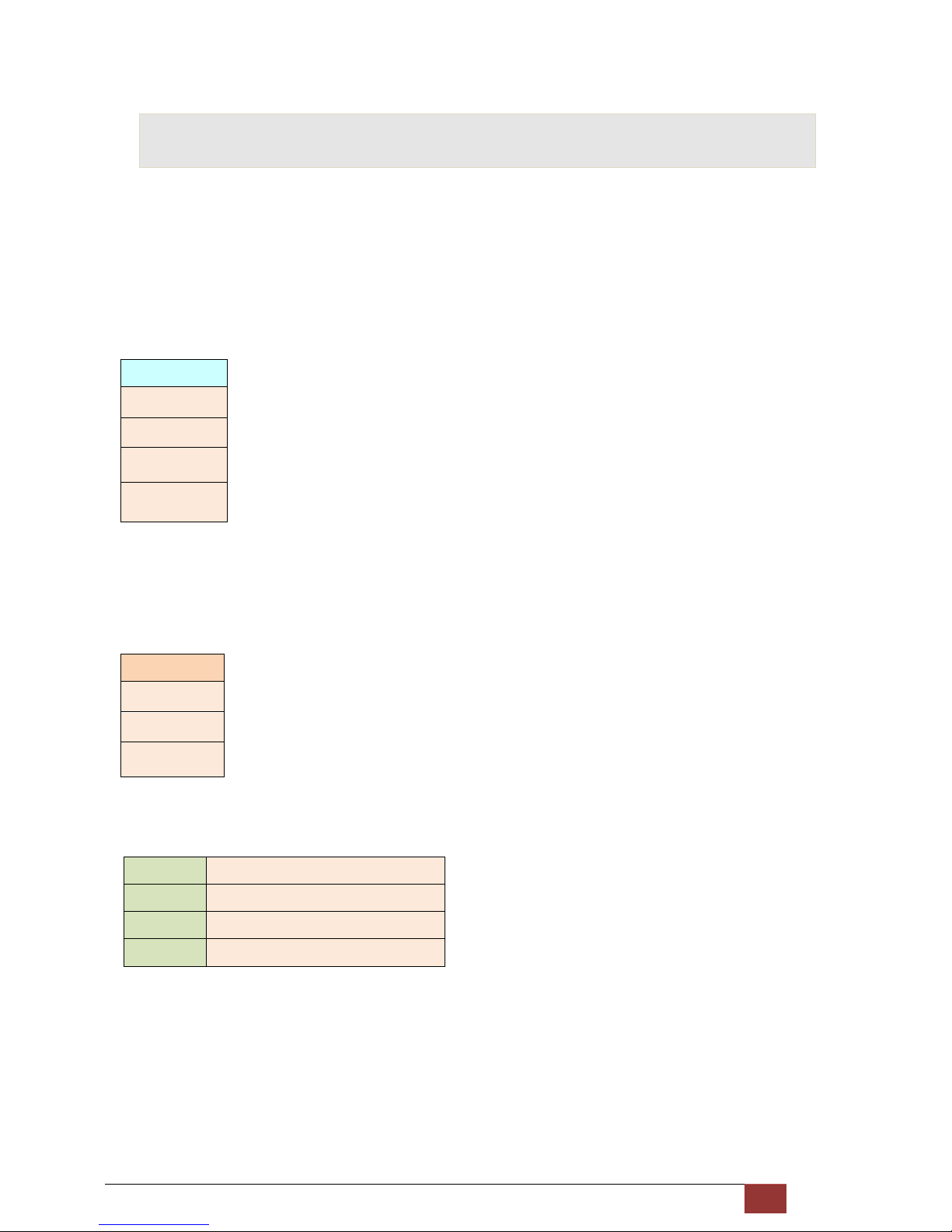
3.3 Menu tree for [SHOW STATUS]
You can check five kinds mode of status via LCD display.
SHOW
STATUS
E1 interface mode:
STATUS
INTERFACE ,
STATUS
SHDSL
STATUS
E1
STATUS
Code Version
.
V.35 interface mode:
STATUS
INTERFACE ,
STATUS
SHDSL
STATUS
SERIAL
STATUS
Code Version.
Page 26

G.SHDSL NTU User Manual V0.03 25
Ethernet interface mode:
STATUS
INTERFACE ,
STATUS
SHDSL
STATUS
ETHERNET
STATUS
Code Version.
E1 and Serial interface mode:
STATUS
INTERFACE ,
STATUS
SHDSL
STATUS
E1
STATUS
SERIAL
STATUS
Code Version
E1 and Ethernet interface mode:
STATUS
INTERFACE ,
STATUS
SHDSL
STATUS
E1
STATUS
ETHERNET
STATUS
Code Version
Page 27
G.SHDSL NTU User Manual V0.03 26
The next levels of their menus tree are as following:
SHOW STATUS > STATUS INTERFACE
STATUS
INTERFACE
* INTERFACE*
SHOW STATUS > STATUS SHDSL
STATUS
SHDSL
* MODE *
* ANNEX *
* LINE RATE *
* ATTENUATION *
* SNR MARGIN *
* TX POWER *
SHOW STATUS > STATUS E1
STATUS
E1
* SIGNAL FRAME *
* LINE CODE *
* CHANNEL *
* SLOT NUMBER *
* FIRST SLOT *
* AIS ALARM *
* BUILD OUTS *
Page 28
G.SHDSL NTU User Manual V0.03 27
SHOW STATUS > STATUS SERIAL
STATUS
SERIAL
* INTERFACE *
* DATA RATE *
* CLOCK *
* SERIAL RTS *
* SERIAL CTS *
* SERIAL DTR *
* SERIAL DSR *
* SERIAL DCD *
* RTS/CTS DELAY *
SHOW STATUS > STATUS ETHERNET
STATUS
ETHERNET
*LINK SPEED*
*OPERATION*
*RATE*
SHOW STATUS > STATUS CODE VERSION
STATUS
CODE VERSION
KERNEL FPGA
Page 29
G.SHDSL NTU User Manual V0.03 28
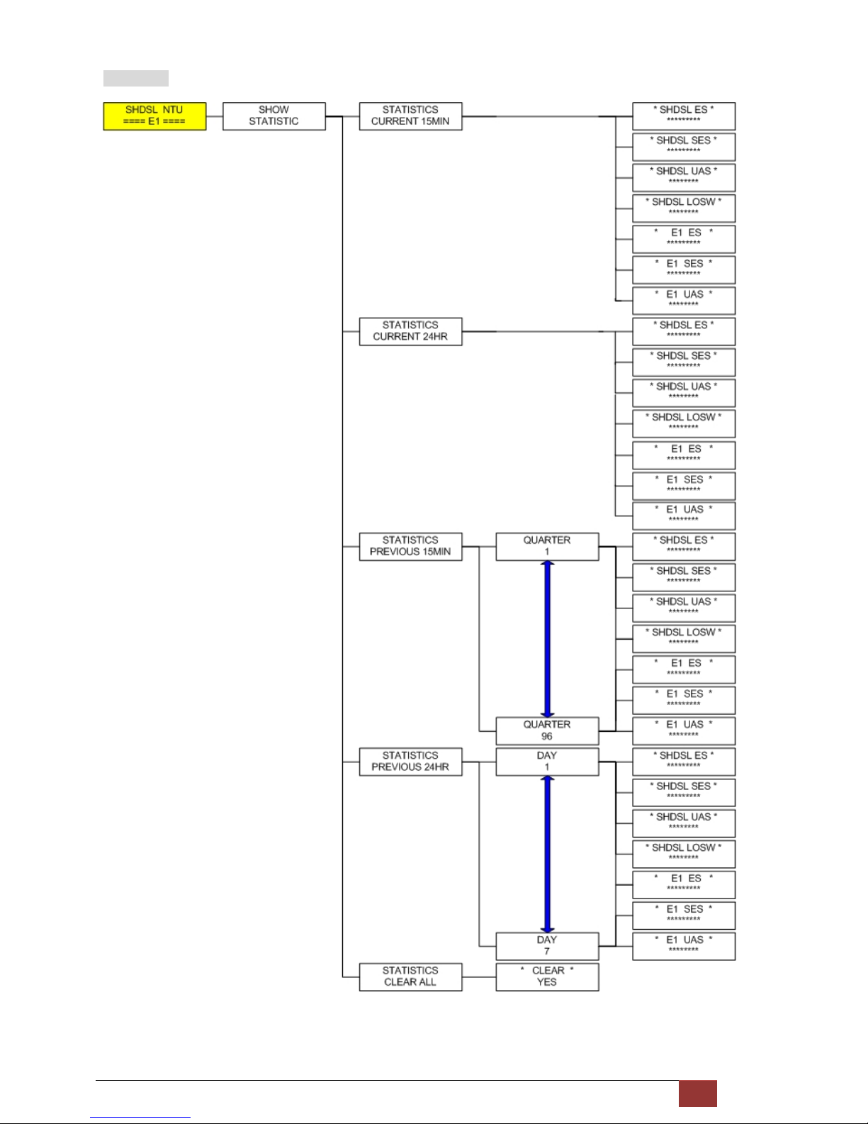
3.4 Menu tree for [SHOW STATISTICS]
The product can display two kinds of statistics data:
SHDSL statistics data [ES, SES, UAS and LOWS]
Show the current 15 minutes period and 96 previous 15-minutes period of SHDSL performance.
Show the current 24 hours period and 7 previous 24-hours periods of SHDSL performance.
SHDSL
ES
SES
UAS
LOSW
E1 statistics data [ES, SES and UAS]
Show the current 15 minutes period and 96 previous 15-minutes period of E1 performance.
Show the current 24 hours period and 7 previous 24-hours periods of E1 performance.
E1
ES
SES
UAS
Abbreviation:
ES
Error Second
SES
Severely Error Second
UAS
Unavailable Second
LOWS
Loss of Synchronization word
Page 30
G.SHDSL NTU User Manual V0.03 29
E1 Interface
Page 31

G.SHDSL NTU User Manual V0.03 30
Serial Interface
Ethernet Interface
E1 and SERIAL Interface
E1 and Ethernet Interface
Page 32

G.SHDSL NTU User Manual V0.03 31
3.5 Menu tree for [SYSTEM SETUP]
You can check five kinds mode of setup type via LCD display.
SYSTEM
SETUP
E1 interface mode:
SETUP
INTERFACE ,
SETUP
SHDSL
SETUP
E1
SETUP
ALLOW RMT CONFIG
SETUP
DEFAULT
SETUP
REMOTE CONFIG
V.35 interface mode:
SETUP
INTERFACE ,
SETUP
SHDSL
SETUP
SERIAL
SETUP
ALLOW RMT CONFIG
SETUP
DEFAULT
SETUP
REMOTE CONFIG
Page 33

G.SHDSL NTU User Manual V0.03 32
Ethernet interface mode:
SETUP
INTERFACE ,
SETUP
SHDSL
SETUP
ETHERNET
SETUP
ALLOW RMT CONFIG
SETUP
DEFAULT
SETUP
REMOTE CONFIG
E1 and Serial interface mode:
SETUP
INTERFACE ,
SETUP
SHDSL
SETUP
E1
SETUP
SERIAL
SETUP
ALLOW RMT CONFIG
SETUP
DEFAULT
SETUP
REMOTE CONFIG
E1 and Ethernet interface mode:
SETUP
INTERFACE ,
SETUP
SHDSL
SETUP
E1
SETUP
ETHERNET
Page 34

G.SHDSL NTU User Manual V0.03 33
SETUP
ALLOW RMT CONFIG
SETUP
DEFAULT
SETUP
REMOTE CONFIG
SYSTEM SETUP > SETUP INTERFACE
SETUP
INTERFACE
Selection items
SETUP INTERFACE E1, SERIAL, ETHERNET, E1+SERIAL, E1+ETHERNET
Model Interface modes support
E1 interface model E1
Serial interface model Serial
Ethernet interface model Ethernet
Multi-interfaces model E1
Serial
Ethernet
E1+Serial
E1+Ethernet
For Multi-interfaces model, there have five types for your selection: E1, Serial, Ethernet, E1+ Serial and
E1+ Ethernet.
Page 35

G.SHDSL NTU User Manual V0.03 34
SYSTEM SETUP > SETUP SHDSL
SETUP
SHDSL
SETUP SHDSL Selection items
SETUP MODE STU-R, STU-C-INTCLK, STU-C-EXTCLK
SETUP ANNEX A, B
SETUP STARTUP MARGIN DISABLE , 0 to 10
SETUP PSD R1_ASTM, R2_ASYM, SYM_ENABLE, ASYM_DISBALE
SETUP POWER BACK OFF Disable, Enable
The following are commonly used acronyms for SETUP MODE:
STU-R RT side, where the clock source is set to external
STU-C-INTCLK CO side, where the clock source is set to internal
STU-C-EXTCLK CO side, where the clock source is set to external
Page 36

G.SHDSL NTU User Manual V0.03 35
3.5.1 Sub-Menu tree for SETUP E1 Interface
SYSTEM SETUP SETUP E1
SETUP
E1
Page 37

G.SHDSL NTU User Manual V0.03 36
E1 parameter setting:
E1 Items Setting
Channel FULL
PCM31
PCM31C
PCM30
PCM30C
Code HDB3
AMI
AIS On
Off
Build Outs 120 ohms
75 ohms
E1 Framer Setting:
Framer Slot Number
First Slot
PCM31 FAS 1 to 31 1 to 31
PCM31C FAS+CRC4 1 to 31 1 to 31
PCM30 FAS+CAS 1 to 30 1 to 31 (can’t use 16)
PCM30C FAS+CAS+CRC4 1 to 30 1 to 31 (can’t use 16)
FULL UNFRAMED
Page 38

G.SHDSL NTU User Manual V0.03 37
Table of number of slots and their first time slot:
Channel Number of slots 1st slot
FULL (UNFRAMED) ----- -----
PCM31 PCM31C 31 1
30 1~2
29 1~3
28 1~4
27 1~5
26 1~6
25 1~7
24 1~8
23 1~9
22 1~10
21 1~11
20 1~12
19 1~13
18 1~14
17 1~15
16 1~16
15 1~17
14 1~18
13 1~19
12 1~20
11 1~21
10 1~22
9 1~23
8 1~24
7 1~25
6 1~26
5 1~27
4 1~28
3 1~29
2 1~30
1 1~31
PCM30 PCM30C 30 1
29 1~2
28 1~3
27 1~4
26 1~5
25 1~6
Page 39

G.SHDSL NTU User Manual V0.03 38
24 1~7
23 1~8
22 1~9
21 1~10
20 1~11
19 1~12
18 1~13
17 1~14
16 1~15
15 1~15,17
14 1~15,17~18
13 1~15,17~19
12 1~15,17~20
11 1~15,17~21
10 1~15,17~22
9 1~15,17~23
8 1~15,17~24
7 1~15,17~25
6 1~15,17~26
5 1~15,17~27
4 1~15,17~28
3 1~15,17~29
2 1~15,17~30
1 1~15,17~31
Page 40

G.SHDSL NTU User Manual V0.03 39
3.5.2 Sub-Menu tree for SETUP SERIES Interface
SYSTEM SETUP SETUP SERIES
SETUP
SERIAL
7
Page 41

G.SHDSL NTU User Manual V0.03 40
Serial Items Setting
INTERFACE V.35
X.21(RS-530)
Nx64K (Rate) 1 ~ 36
CLOCK Normal
Inverse
RTS On
From DTE
CTS On
Off
From RTS
DSR On
Off
From DTR
DCD On
Off
From DSL
DELAY 0mS
1mS
2mS
3mS
The handshake signal direction between DCE and DTE
The below diagram shows CTS follow RTS, DSR follow DTR
Page 42

G.SHDSL NTU User Manual V0.03 41
The RTS delay time is use to control CTS on delay to RTS signal, It is work only for the setting:
CTS follow RTS and RTS follow from DTE
Page 43

G.SHDSL NTU User Manual V0.03 42
3.5.3 Sub-Menu tree for SETUP Ethernet Interface
SYSTEM SETUP SET UP ETHERNET
SETUP
ETHERNET
If you set Ethernet Auto Negotiation is as Enable, the Duplex and Speed can’t be set up and using auto
configuration.
Ethernet Items Setting
Rate 1 ~ 36
Auto Disable Enable
Duplex Full-Duplex
Half-Duplex
Auto Configuration
Speed 100M
10M
Auto Configuration
Page 44

G.SHDSL NTU User Manual V0.03 43
3.5.4 Application of Multi-interfaces
Case 1 E1(Unframed)+ Serial interface --------- E1(Unframed)+ Serial interface
Case 2 E1(Frame)+ Serial interface --------- E1(Frame)+ Serial interface
Case 3 E1(Frame)+ Ethernet interface --------- E1(Frame)+ Ethernet interface
Case 4 E1(Frame)+ Serial interface --------- E1(Frame)+ Ethernet interface
Page 45

G.SHDSL NTU User Manual V0.03 44
Table of E1+ Serial interface and E1+Ethernet interface mode on both sides
E1 interface Serial interface
Ethernet interface
Channel Number of slot 1st slot Nx64K (Rate)
FULL (UNFRAMED) ----- ----- 1~4
PCM31 PCM31C 31 1 1~5
30 1~2 1~6
29 1~3 1~7
28 1~4 1~8
27 1~5 1~9
26 1~6 1~10
25 1~7 1~11
24 1~8 1~12
23 1~9 1~13
22 1~10 1~14
21 1~11 1~15
20 1~12 1~16
19 1~13 1~17
18 1~14 1~18
17 1~15 1~19
16 1~16 1~20
15 1~17 1~21
14 1~18 1~22
13 1~19 1~23
12 1~20 1~24
11 1~21 1~25
10 1~22 1~26
9 1~23 1~27
8 1~24 1~28
7 1~25 1~29
6 1~26 1~30
5 1~27 1~31
4 1~28 1~32
3 1~29 1~33
2 1~30 1~34
1 1~31 1~35
PCM30 PCM30C 30 1 1~6
29 1~2 1~7
28 1~3 1~8
27 1~4 1~9
Page 46

G.SHDSL NTU User Manual V0.03 45
26 1~5 1~10
25 1~6 1~11
24 1~7 1~12
23 1~8 1~13
22 1~9 1~14
21 1~10 1~15
20 1~11 1~16
19 1~12 1~17
18 1~13 1~18
17 1~14 1~19
16 1~15 1~20
15 1~15,17 1~21
14 1~15,17~18 1~22
13 1~15,17~19 1~23
12 1~15,17~20 1~24
11 1~15,17~21 1~25
10 1~15,17~22 1~26
9 1~15,17~23 1~27
8 1~15,17~24 1~28
7 1~15,17~25 1~29
6 1~15,17~26 1~30
5 1~15,17~27 1~31
4 1~15,17~28 1~32
3 1~15,17~29 1~33
2 1~15,17~30 1~34
1 1~15,17~31 1~35
Page 47

G.SHDSL NTU User Manual V0.03 46
Case 5 E1(frame)+ Serial interface --------- E1(frame)
Case 6 E1(frame)+Ethernet interface ---------E1(frame)
Table of E1+ Serial interface and E1+Ethernet interface mode on local side and E1 interface on remote side
E1 interface Serial interface
Ethernet interface
Channel Number of slot 1st slot location Nx64K (Rate) range
PCM31 PCM31C 31 1 1
30 1~2 1~2
29 1~3 1~3
28 1~4 1~4
27 1~5 1~5
26 1~6 1~6
25 1~7 1~7
24 1~8 1~8
23 1~9 1~9
22 1~10 1~10
21 1~11 1~11
20 1~12 1~12
19 1~13 1~13
18 1~14 1~14
17 1~15 1~15
Page 48

G.SHDSL NTU User Manual V0.03 47
16 1~16 1~16
15 1~17 1~17
14 1~18 1~18
13 1~19 1~19
12 1~20 1~20
11 1~21 1~21
10 1~22 1~22
9 1~23 1~23
8 1~24 1~24
7 1~25 1~25
6 1~26 1~26
5 1~27 1~27
4 1~28 1~28
3 1~29 1~29
2 1~30 1~30
1 1~31 1~31
PCM30 PCM30C 30 1 1~2
29 1~2 1~3
28 1~3 1~4
27 1~4 1~5
26 1~5 1~6
25 1~6 1~7
24 1~7 1~8
23 1~8 1~9
22 1~9 1~10
21 1~10 1~11
20 1~11 1~12
19 1~12 1~13
18 1~13 1~14
17 1~14 1~15
16 1~15 1~16
15 1~15,17 1~17
14 1~15,17~18 1~18
13 1~15,17~19 1~19
12 1~15,17~20 1~20
11 1~15,17~21 1~21
10 1~15,17~22 1~22
9 1~15,17~23 1~23
8 1~15,17~24 1~24
7 1~15, 17~25 1~25
Page 49

G.SHDSL NTU User Manual V0.03 48
6 1~15, 17~26 1~26
5 1~15, 17~27 1~27
4 1~15, 17~28 1~28
3 1~15, 17~29 1~29
2 1~15, 17~30 1~30
1 1~15, 17~31 1~31
Page 50

G.SHDSL NTU User Manual V0.03 49
3.6 Menu tree for [REBOOT SYSTEM]
REBOOT
SYSTEM
While use the REBOOT SYSTEM command, press “ENTER” Key; select ”YES” and press ”ENTER” Key. You can see the
“Reboot…” display. It will return to main menu after the reboot operation is finish.
Page 51

G.SHDSL NTU User Manual V0.03 50
3.7 Menu tree for [SYSTEM DISGNOSTIC]
SYSTEM
DIAGNOSTIC
System Diagnostic has two functions: Loopback test and BER test.
SYSTEM DIAGNOSTIC DIAG LOOPBACK
DIAG
LOOPBACK
SYSTEM DIAGNOSTIC DIAG BER TEST
DIAG
BER TEST
Page 52

G.SHDSL NTU User Manual V0.03 51
Page 53

G.SHDSL NTU User Manual V0.03 52
3.7.1 Loopback Test
Note : No SYSTEM DIAGNOSTIC menu on Ethernet Interface Model
For E1 Interface model as CO side, there have: local digital, local, remote line, remote payload, farend line and
farend payload.
For Serial Interface model as CO side, there have: Local digital, local, remote line, remote payload, farend line,
farend payload and V.54.
For E1 Interface model as CPE side, there have: local digital, remote line, remote payload, farend line and farend
payload.
For Serial Interface model as CPE side, there have: Local digital, remote line, remote payload, farend line, farend
payload and V.54.
If the device haven’t connect or under handshake, there will not have farend line, farend payload and V.54.
Definition of
V.54
An ITU standard (1976) for various loopback tests that can be incorporated into modems for testing the telephone
circuit and isolating transmission problems.
Operating modes include local and remote digital loopback and local and remote analog loopback.
Page 54

G.SHDSL NTU User Manual V0.03 53
Stand alone NTU, no connection with other NTU:
E1 interface
CO side
Serial interface
CO side
Local digital Local digital
Local Local
Remote line Remote line
Remote payload Remote payload
E1 interface
CPE side
Serial interface
CPE side
Local digital Local digital
Remote line Remote line
Remote payload Remote payload
After connection both CO side and CPE side:
E1 interface
CO side
Serial interface
CO side
Local digital Local digital
Local Local
Remote line Remote line
Remote payload Remote payload
Farend line Farend line
Farend payload Farend payload
V.54
E1 interface
CPE side
Serial interface
CPE side
Local digital Local digital
Remote line Remote line
Remote payload Remote payload
Farend line Farend line
Farend payload Farend payload
V.54
Page 55

G.SHDSL NTU User Manual V0.03 54
Page 56

G.SHDSL NTU User Manual V0.03 55
3.7.2 BER Test
This is the internal Bit Error Rate Tester (BERT) for complete testing of local and remote modem and the link quality
without any external test equipment.
This built-in Bit Error Rate Test generator can generates a standard 2047 (211-1) test pattern.
DIAG
BER TEST
*BERT 2047*
RUN
When the BERT haven’t any Bit Error, it show zero. Otherwise, it will show some number counter.
RUN(SEC) item is show the time elapsed second count
RUN(SEC): 00001
BIT ERR: 00000
If there have NO SYNC on bit error message, it shows the testing paths haven’t connected.
RUN(SEC): 00001
BIT ERR: NO SYNC
Press ENTER key on this display message, it will re-sync again.
*BERT 2047*
RESYNC
Press ENTER key on this display message, it will show the test real time.
*BERT 2047*
INFO
If you want to exit the BERT, you can press ENTER key from this display message.
*BERT 2047*
DISABLE
Page 57

G.SHDSL NTU User Manual V0.03 56
3.8 Parameters Table
3.8.1 E1 Interface Model
NTU Type
□
STU-R □STU-C-INTCLK □STU-C-EXTCLK
SHDSL
Annex
□
A □B
PSD
□
R1_ASTM □R2_ASYM □SYM_ENABLE □ASYM_DISABLE
SNR Margin
□
DISABLE □0 □1 □2 □3 □4 □5 □6 □7 □8 □9 □10
Power Back Off
□
Disable □Enable
E1
Channel
□
PCM31 □PCM31C □PCM30 □PCM30C □Unframed
Slot Number
First Slot
Code
□
HDB3 □AMI
AIS
□
Off □On
Build Outs
□
75 Ohm □120 Ohm
3.8.2 Serial Interface Model
NTU Type
□
STU-R □STU-C-INTCLK □STU-C-EXTCLK
SHDSL
Annex
□
A □B
PSD
□
R1_ASTM □R2_ASYM □SYM_ENABLE □ASYM_DISABLE
SNR Margin
□
DISABLE □0 □1 □2 □3 □4 □5 □6 □7 □8 □9 □10
Power Back Off
□
Disable □Enable
Serial
Interface
□
V.35 □X.21
Data Rate
Clock
□
Normal □Inverse
RTS
□
On □From DTE
CTS
□
On □Off □From RTS
DSR
□
On □Off □From DTR
DCD
□
On □Off □From DSL
Delay
□
0mS □1mS □2mS □3mS
Page 58

G.SHDSL NTU User Manual V0.03 57
3.8.3 Ethernet Interface model
NTU Type
□
STU-R □STU-C-INTCLK □STU-C-EXTCLK
SHDSL
Annex
□
A □B
PSD
□
R1_ASTM □R2_ASYM □SYM_ENABLE □ASYM_DISABLE
SNR Margin
□
DISABLE □0 □1 □2 □3 □4 □5 □6 □7 □8 □9 □10
Power Back Off
□
Disable □Enable
Ethernet
Date Rate
Auto Config
□
Disable □Enable
Speed
□
Full □Half
Duplex
□
100M □10M
3.8.4 Multi-interface model--E1 Interface
NTU
Interface
⊠
E1 □Serial □Ethernet □E1+Serial □E1+Ethernet
Type
□
STU-R □STU-C-INTCLK □STU-C-EXTCLK
SHDSL
Annex
□
A □B
PSD
□
R1_ASTM □R2_ASYM □SYM_ENABLE □ASYM_DISABLE
SNR Margin
□
DISABLE □0 □1 □2 □3 □4 □5 □6 □7 □8 □9 □10
Power Back Off
□
Disable □Enable
E1
Channel
□
PCM31 □PCM31C □PCM30 □PCM30C □Unframed
Slot Number
First Slot
Code
□
HDB3 □AMI
AIS
□
Off □On
Build Outs
□
75 Ohm □120 Ohm
Page 59

G.SHDSL NTU User Manual V0.03 58
3.8.5 Multi-interface model--Serial Interface
NTU Interface
□
E1 ⊠Serial □Ethernet □E1+Serial □E1+Ethernet
Type
□
STU-R □STU-C-INTCLK □STU-C-EXTCLK
SHDSL
Annex
□
A □B
PSD
□
R1_ASTM □R2_ASYM □SYM_ENABLE □ASYM_DISABLE
SNR Margin
□
DISABLE □0 □1 □2 □3 □4 □5 □6 □7 □8 □9 □10
Power Back Off
□
Disable □Enable
Serial
Interface
□
V.35 □X.21
Data Rate
Clock
□
Normal □Inverse
RTS
□
On □From DTE
CTS
□
On □Off □From RTS
DSR
□
On □Off □From DTR
DCD
□
On □Off □From DSL
Delay
□
0mS □1mS □2mS □3mS
3.8.6 Multi-interface model--Ethernet Interface
NTU Interface
□
E1 □Serial ⊠Ethernet □E1+Serial □E1+Ethernet
Type
□
STU-R □STU-C-INTCLK □STU-C-EXTCLK
SHDSL
Annex
□
A □B
PSD
□
R1_ASTM □R2_ASYM □SYM_ENABLE □ASYM_DISABLE
SNR Margin
□
DISABLE □0 □1 □2 □3 □4 □5 □6 □7 □8 □9 □10
Power Back Off
□
Disable □Enable
Ethernet
Date Rate
Auto Config
□
Disable □Enable
Speed
□
Full □Half
Duplex
□
100M □10M
Page 60

G.SHDSL NTU User Manual V0.03 59
3.8.7 Multi-interface model--E1+Serial Interface
NTU
Interface
□
E1 □Serial □Ethernet ⊠E1+Serial □E1+Ethernet
Type
□
STU-R □STU-C-INTCLK □STU-C-EXTCLK
SHDSL
Annex
□
A □B
PSD
□
R1_ASTM □R2_ASYM □SYM_ENABLE □ASYM_DISABLE
SNR Margin
□
DISABLE □0 □1 □2 □3 □4 □5 □6 □7 □8 □9 □10
Power Back Off
□
Disable □Enable
E1
Channel
□
PCM31 □PCM31C □PCM30 □PCM30C □Unframed
Slot Number
First Slot
Code
□
HDB3 □AMI
AIS
□
Off □On
Build Outs
□
75 Ohm □120 Ohm
Serial
Interface
□
V.35 □X.21
Data Rate
Clock
□
Normal □Inverse
RTS
□
On □From DTE
CTS
□
On □Off □From RTS
DSR
□
On □Off □From DTR
DCD
□
On □Off □From DSL
Delay
□
0mS □1mS □2mS □3mS
Page 61

G.SHDSL NTU User Manual V0.03 60
3.8.8 Multi-interface model--E1+Ethernet Interface
NTU
Interface
□
E1 □Serial □Ethernet □E1+Serial ⊠E1+Ethernet
Type
□
STU-R □STU-C-INTCLK □STU-C-EXTCLK
SHDSL
Annex
□
A □B
PSD
□
R1_ASTM □R2_ASYM □SYM_ENABLE □ASYM_DISABLE
SNR Margin
□
DISABLE □0 □1 □2 □3 □4 □5 □6 □7 □8 □9 □10
Power Back Off
□
Disable □Enable
E1
Channel
□
PCM31 □PCM31C □PCM30 □PCM30C □Unframed
Slot Number
First Slot
Code
□
HDB3 □AMI
AIS
□
Off □On
Build Outs
□
75 Ohm □120 Ohm
Ethernet
Date Rate
Auto Config
□
Disable □Enable
Speed
□
Full □Half
Duplex
□
100M □10M
Page 62

G.SHDSL NTU User Manual V0.03 61
4 Configuration with Console Port
This chapter will deal with the specifics of configuration and operation of this product via console port with terminal
emulation program. The configuration G.SHDSL NTU is performed via a menu-driven embedded software, using a
standard ASCII terminal or a PC running a terminal emulation application connected to the rear panel CONSOLE port.
Windows includes a terminal emulation program called HyperTerminal. Connect the appropriate communication
port from the PC to this device. After the physical connection is made, you are ready to configure this product. Make
sure you have connected the supplied RS-232C serial cable (DB9F to RJ-45 Plug) to the console port on the rear panel
on this product.
Run the terminal emulation program such as Hyper Terminal with the following setting:
Emulation: VT-100 compatible
Band rate: 115200, Data bits: 8, Parity: None, Stop Bits:1 , Flow Control: None
4.1 Login Procedure
At the start up screen, you will see:
Page 63

G.SHDSL NTU User Manual V0.03 62
Press the SPACE key until the login screen appears. When you see the login screen, you can logon to device.
Username use “admin”. When the system prompts you for a password, type “admin” to enter is O.K.
Page 64

G.SHDSL NTU User Manual V0.03 63
4.2 Window structure
After you type the password, it will display the main menu.
Above screen capture shows the common structure for all windows used throughout the configuration console
terminal.
From top to bottom, the window is divided into four major sections.
The very top line displays the product name.
Next a block of commands is listed where the ">>" symbol indicates the current cursor placeholder.
The next block down is the "command" section. The command that is selected and ready for execution is displayed
after the "Command:" prompt. The "<more…> designation indicates that there are other sub menus to this
command. The "Message:" field is used to display any special system messages or warnings.
Finally, at the very bottom of the screen is a help command line and reminder of the currently available command
keys. In most cases, the keyboards four cursor keys can be used to navigate all the menu system. If for some reason
your keyboard's cursor keys are not supported in the terminal emulation software, you may uses the keys listed on
the help command line.
Page 65

G.SHDSL NTU User Manual V0.03 64
4.3 Menu Commands
Before changing the configuration, familiarize yourself with the operations list in the following table. The operation
list will be shown on the window.
Keypads Description
[UP] or I Move to above field in the same level menu
[DOWN] or K Move to below field in the same lever menu
U Move to top field in the same level menu
O Move to bottom field in the same level menu
[LEFT] or J Move back to previous menu (Exit)
[RIGHT] , L or [ENTER] Move forward to submenu(Enter)
[TAB] To choose another parameters
Ctrl + C To quit the show data display screen
Page 66

G.SHDSL NTU User Manual V0.03 65
4.4 Main Menu Summary
The main menu is prompt as follow.
Menu Title Function
Setup To setup SHDSL type, SHDSL parameters and E1/Serial/Ethernet
parameters or restore factory default setting.
Status To show SHDSL status, E1 /V.35/Ethernet status and statistics or clear the
statistics on both local and remote side.
Show To show general information, all configurations and all configurations in
command script format.
Reboot To reboot the system
Diag To setup diagnostic utility
Upgrade To upgrade firmware (kernel and FPGA code)
Exit To exit this system
Page 67

G.SHDSL NTU User Manual V0.03 66
4.5 [Setup] Configuration
This section provides information about configuration the G.SHDSL NTU. Follow the procedures:
In main menu, select setup and press [ENTER] or [RIGHT]
Press [ENTER] or [L] key to select which channel (Local side or Remote side).
Page 68

G.SHDSL NTU User Manual V0.03 67
The screen will prompt as following:
E1 interface model
You can see E1 parameter can been setting.
Serial interface model
You can see Serial parameter can been setting.
Page 69

G.SHDSL NTU User Manual V0.03 68
Ethernet interface model
You can see Ethernet parameter can been setting.
E1 and Serial interface model
You can see the E1 and Serial parameters can been setting.
Page 70

G.SHDSL NTU User Manual V0.03 69
E1 and Ethernet interface model
You can see the E1 and Ethernet parameters can been setting.
Page 71

G.SHDSL NTU User Manual V0.03 70
4.5.1 Configure Interface
Select Interface item, and press [ENTER] or [RIGHT] to setup NTU Interface.
Press [TAB] to select the operating type and press enter to finish setting.
Page 72

G.SHDSL NTU User Manual V0.03 71
Model Interface modes support
E1 interface model E1
Serial interface model Serial
Ethernet interface model Ethernet
Multi-interfaces model E1
Serial
Ethernet
E1+Serial
E1+Ethernet
For Multi-interfaces model, there have five types for your selection: E1, Serial, Ethernet, E1+ Serial and
E1+ Ethernet.
Page 73

G.SHDSL NTU User Manual V0.03 72
4.5.2 Configure SHDSL parameters
This section will introduce the configuring of SHDSL parameters.
Select Shdsl , and press [ENTER] or [RIGHT].
The SHDSL parameters items have SHDSL Mode, Annex type, PSD, SNR margin and Power backoff.
For configuring SHDSL mode, move the cursor to Mode and press [ENTER] or [L]. Select the SHDSL mode by using
[TAB] key.
Page 74

G.SHDSL NTU User Manual V0.03 73
Setup SHDSL parameter, Mode
There are three SHDSL modes can be used: STU-R, STU-C-INTCLK and STU-C-EXTCLK.
INTCLK: The device will generate the appropriate clock speed defined by the speed setting of the interface.
EXTCLK: The device will accept the clock from the interface and will use that clock to receive and transmit data
across the interface.
Most applications use Internal Clock. If the DTE provides a clock with TX data, the clock can set to be External Clock.
Page 75

G.SHDSL NTU User Manual V0.03 74
For configuring SHDSL Annex type, move the cursor to Annex and press [ENTER or [L]]. Select the Annex type by
using [TAB] key.
Setup SHDSL parameter, Annex
There are two annex type can be used: Annex-A and Annex-B
Page 76

G.SHDSL NTU User Manual V0.03 75
For configuring SHDSL PSD, move the cursor to psd and press [ENTER] or [L]. Select the parameter by using [TAB]
key.
Setup SHDSL parameter, PSD
There are four PSD type can be used: R1_ASM, R2_ASM, SYM_ENABLE and ASYM_DISABLE.
Page 77

G.SHDSL NTU User Manual V0.03 76
For setting SHDSL Margin, move the cursor to margin and press [ENTER] or [L]. You can key the SHDSL margin setting
value.
Setup SHDSL parameter, SNR Margin
SNR margin is an index of line connection. You can see the actual SNR margin from 0 to 10 in STATUS SHDSL. The
larger SNR margin has the better line connection. For example, if you set SNR margin in the field as 3, the SHDSL
connection will drop down and reconnect when the SNR margin is lower than 3.
Page 78

G.SHDSL NTU User Manual V0.03 77
For configuring SHDSL Power Back off function, move the cursor to Pwr Backoff and press [ENTER] or [L]. Select the
parameter by using [TAB] key.
Setup SHDSL parameter, Power Backoff
There are two power back-off type can be used: Disable and Enable.
Page 79

G.SHDSL NTU User Manual V0.03 78
4.5.3 Configure E1 parameters
When using on E1 interface, select the E1 item and press [ENTER] or [RIGHT].
The E1 settings include Channel, line code, AIS and build out settings.
Setup E1 Parameter, Channel
Page 80

G.SHDSL NTU User Manual V0.03 79
Framing is required to recover the channelized E1. In transparent operation, the framing is configured as Unframed.
In this case the G.SHDSL framer must be set to Nx64 with N=32. For any framing such as FAS or CAS, the G.SHDSL
framer must be set to E1, then the E1 framing here may be set accordingly. The default setting is PCM31C.
Channel Framing
PCM31 FAS
PCM31C FAS+CRC4
PCM30 FAS+CAS
PCM30C FAS+CAS+CRC4
FULL Unframed E1 (transparent)
PCM31 and PCM31C / FAS and FAS+CRC4
FAS
0 1 2 3 4 5 6 7
8 31
Time Slot
64k 64k 64k 64k 64k 64k 64k 64k 64k 64k1408k
9 ~ 30
Maximun Data Rate 1948kbps
CAS
Also known as time slot 16 multiframing. It requires a multiframe alignment
signal to be present for frame sync. The Multiframe Alignment Signal (MFAS) is
inserted into the 16th timeslot of frame 0 of the 16-frame multiframe.
In CAS mode, there have 30 channels available for user data. If timeslot 16 is
included in the unit’s mapping, it will be disregarded.
FAS
Frame Alignment Signal use 7-bit pattern to establish and maintain frame
synchronization. The FAS word is located in timeslot 0 of frame. In FAS mode there
have 1~31 timeslot available for use data.
Page 81

G.SHDSL NTU User Manual V0.03 80
PCM30 and PCM30C / FAS+CAS and FAS+CAS+CRC4
FAS
0 1 2 3 4 16
31
Time Slot
64k 64k 64k 64k 64k 64k 64k896k
17 ~ 30
CAS
5 ~ 15
704k
Data Rate (x) 960kbps Data Rate (y) 960kbps
Maximun Data Rate = x + y = 1920kbps
CRC4
The CRC-4 checksum bits are transmitted in the outgoing E1 data stream.
Also the received signal is checked for errors.
CRC-4 checksum cannot be sent in unframed mode.
Unframed
In this mode, user data is inserted into all 32 channels (64k x 32 = 2048k) of
the E1 stream. The object of running without framing is to utilize the full
bandwidth of the E1 line.
UNFRAMED
0 1 2 3 4 5 6 7
8 31
Time Slot
64k 64k 64k 64k 64k 64k 64k 64k 64k 64k1408k
9 ~ 30
Maximun Data Rate 2048kbps
G.703 (E1) can supports data rate of 2048kbps, so the maximum data rate of SHDSL line, connected with E1 DCEs,
depends on data rate of E1, 2048kbps.
STU-C (E1)
STU-R (E1) DTEDTE
E1
E1 SHDSL
Frame E1
Data rate 2048
If the connection is E1 vs V.35 or V.35 vs E1, the frame has to be used N x 64k. In this case, the data rate depends on
value of N. Same as above case, SHDSL and V35 can support 2304kbps data rate (36 x 64k) but E1 supports
maximum data rate of 2048kbps (32 x 64k).
Page 82

G.SHDSL NTU User Manual V0.03 81
STU-C (E1)
STU-R
(V.35)
DTEDTE
V.35
E1 SHDSL
Frame N x 64 (N=1~32)
STU-C (V.35)
STU-R (E1) DTEDTE
E1
V.35 SHDSL
Frame N x 64 (N=1~32)
Time slot, N value, is place of data in the frame. Time Slot Number 1~31 (N=1~31) is Fractional E1 and Time Slot
Number 32 (N=32) is unframed.
Fractional E1
For fractional E1( FE1), the data rate is from 64k, N=1, to 1984k, N=31, according to the E1 frame.
If the E1 frame is PCM31(FAS) or PCM31C(FAS+CRC4), there have 1~31 available time slot for used data.
For example, if the data rate of SHDSL line set to be 512k, the time slot number is 8 and first time slot number is 1.
The frame is shown as below.
FAS Data Data Data Data Data Data Data Data
0 1 2 3 4 5 6 7
8 31
Time Slot
64k 64k 64k 64k 64k 64k 64k 64k 64k 64k1408k
9 ~ 30
The First Time Slot setting of FAS and FAS+ CRC4 (PCM31 and PCM31C)have to follow the rule:
RULE
First Time Slot ≦ 31- Time Slot Number
First Time Slot ≦ 31- Time Slot Number
Page 83

G.SHDSL NTU User Manual V0.03 82
Using E1 frame of FAS+CAS or FAS+CAS+CRC4(PCM30 or PCM30C), the [FAS] will occupy Time Slot 0 and [CAS] will
occupy Time Slot 16. There have only 30 Time Slot left for data. On the other hand, the data rate is 1920kbps
(30x64Kbps).
FAS
0 1 2 3 4 16
31
Time Slot
64k 64k 64k 64k 64k 64k 64k896k
17 ~ 30
CAS
5 ~ 15
704k
The First Time Slot setting of FAS+CAS and FAS+CAS+CRC4 (PCM30 and PCM30C) have to follow the rule:
RULE
First Time Slot ≦ 30 - Time Slot Number
First Time Slot ≦ 30 - Time Slot Number
Unframed E1
Used data is inserted into all 32 channels (64Kbps x 32 = 2048Kpbs) of the E1 stream
Data Data Data Data Data Data Data Data Data Data Data
0 1 2 3 4 5 6 7
8 31
Time Slot
64k 64k 64k 64k 64k 64k 64k 64k 64k 64k1408k
9 ~ 30
Page 84

G.SHDSL NTU User Manual V0.03 83
Setup E1 Parameter, Line Code
The G.SHDSL NTU supports two different line codes: HDB3 and AMI.
HDB3 is the most popular and preferred line coding and is also the default setting.
AMI line coding is also selectable.
HDB3
In this line coding, the transmitter substitutes a deliberate bipolar violation when excessive
zeros in the data stream are detected. The receiver recognizes these special violations and
decodes them as zeros. This method enables the network to minimum pulse density
requirements. Unless AMI is required for your application, HDB3 should be used whenever
possible.
AMI
Alternate Mark Inversion defines a pulses as a “mark,” a binary one as, as opposed to a
zero. In an E1 network connection, signals are transmitted as a sequence of one and zero.
One is sent as pulse, and zero is sent as spaces, i.e. no pulse. Every other pulse is inverted
from the previous pulse in polarity, so that the signal can be effectively transmitted. This
means, however, that a long sequence of zero in data stream will cause problems, since
the NTU receiving the signal relies on the signal to recover the 2048kbps clock.
Page 85

G.SHDSL NTU User Manual V0.03 84
Setup E1 Parameter, AIS
AIS (Alarm Indication Signal) is a method to inform the remote connection that there is a signal or sync problem with
the E1. AIS is only valid in framed mode E1, not in Unframed E1. The setting here of AIS enabled (on) or not (off) and
is for testing with AIS. When enabled, the E1 will transmit the AIS and it should be confirmed at the remote device
(AIS indication lit). After testing, please turn AIS back off.
For example 1: When STU-R E1 RX line is drop, STU-R sends the status to STU-C via EOC or command, and then
STU-C will send AIS (Alarm Indication Signal) to DTE while AIS function is enabled.
For example 2: When SHDSL connection drops, STU-R and STU-C both send AIS (Alarm Indication Signal) to DTE in
the same time while AIS function is enabled.
Page 86

G.SHDSL NTU User Manual V0.03 85
Setup E1 Parameter, Build Out
The G.SHDSL NTU can support both unbalanced E1 at 75 ohms and balanced E1 at 120 ohms. The settings for
impedance are made here under the build out menu setting.
Page 87

G.SHDSL NTU User Manual V0.03 86
4.5.4 Configure Serial parameters
When using on Serial interface, select the Serial item and press [ENTER] or [RIGHT].
The serial settings include the Interface, data rate, clocking and handshaking lines (RTS, CTS, DSR and DCD) setup etc.
Page 88

G.SHDSL NTU User Manual V0.03 87
Setup Serial Parameter, Interface
You can set serial interface as V.35 or RS-530(X.21) hardware standard.
Setup Serial Parameter, Data Rate
For serial data rate, the default setting is N=32. The date rate can be adjusted in increments of 64kbps from 64kbps
to 2304kbps (N=1~36).
Page 89

G.SHDSL NTU User Manual V0.03 88
Setup Serial Parameter, Clock Polarity
The data port clock polarity may be adjusted to solve some rare clocking issues. The default setting is 'Normal' clock
polarity, where data is sent on the positive transition of the clock, while the option exists to set inverse clock polarity
where data is sent on the negative clock transition.
Page 90

G.SHDSL NTU User Manual V0.03 89
Setup Serial Parameter, RTS
The behavior of the RTS (Request To Send) signal may be set in one of two ways. When set 'on', the RTS signal is
always forced high (on, positive voltage or SPACE), when set 'from DTE' the RTS signal will follow the DTE's condition.
The default setting for RTS is ON.
Page 91

G.SHDSL NTU User Manual V0.03 90
Setup Serial Parameter, CTS
The behavior of the CTS (Clear To Send) signal may be set in one of three ways. When set 'on', the CTS signal is
always forced high (on, positive voltage or SPACE), when set 'off' the signal is always forced low (off, negative
voltage or MARK), or CTS will follow RTS (Request To Send) condition of 'on' for RTS on 'off' for RTS off. The default
setting for CTS is to follow RTS.
Page 92

G.SHDSL NTU User Manual V0.03 91
Setup Serial Parameter, DSR
The behavior of the DSR (Data Set Ready) signal may be set in one of three ways. When set 'on', the DSR signal is
always forced high (on, positive voltage or SPACE), when set 'off' the signal is always forced low (off, negative
voltage or MARK), or DSR will follow DTR (Data Terminal Ready) condition of 'on' for DTR on or 'off' for DTR off. The
default setting for DSR is ON.
Page 93

G.SHDSL NTU User Manual V0.03 92
Setup Serial Parameter, DCD
The behavior of the DCD (Data Carrier Detect) signal may be set in one of three ways. When set 'on', the DCD signal
is always forced high (on, positive voltage or SPACE), when set 'off' the signal is always forced low (off, negative
voltage or MARK), or DCD will follow the DSL condition of 'on' for DSL link or 'off' for DSL no link. The default setting
for DCD is to follow the DSL link status.
Page 94

G.SHDSL NTU User Manual V0.03 93
Setup Serial Parameter, Delay
The delay setting is used to cause a delay for CTS to follow RTS. The delay setting may be set from 0 to 3 milliseconds.
The default setting is 3 milliseconds.
Page 95

G.SHDSL NTU User Manual V0.03 94
4.5.5 Configure Ethernet parameters
When using on Ethernet interface mode, select the Ethernet item and press [ENTER] or [RIGHT].
The Ethernet settings include the data rate, auto config, duplex and speed.
Page 96

G.SHDSL NTU User Manual V0.03 95
Setup Interface Parameter, Data Rate
For date rate, the default setting is 36, or full rate. The date rate can be adjusted in increments of 64kbps from
64kbps to 2304kbps (N=1~36).
Setup Ethernet Parameter, Auto Configuration
You can select Enable and Disable on auto configuration.
Page 97

G.SHDSL NTU User Manual V0.03 96
When auto configuration set enable, the other parameter Duplex and Speed can’t need to setup.
On this case, the message will show as ”Ethernet is in auto negotiate”
Page 98

G.SHDSL NTU User Manual V0.03 97
If auto configuration set disable, the other parameter Duplex and Speed can setup.
Setup Ethernet Parameter, Duplex
You can set up the duplex mode is Full-Duplex and Half-Duplex.
Setup Ethernet Parameter, Speed
You can set up the Ethernet speed is 10Mbps or 100Mbps.
Page 99

G.SHDSL NTU User Manual V0.03 98
4.5.6 Enable and Disable Remote configuration
You can set the “Enable/Disable Remote Config Capability” to let the remote side can configure parameters to this
device remotely.
Page 100

G.SHDSL NTU User Manual V0.03 99
4.5.7 Restore factory default setting
The G.SHDSL NTU can have all settings restored to their original factory settings simply by going to the setting menu,
selecting the Default item, and then press ENTER. The system will ask for a y(es) or n(o) confirmation followed by an
ENTER.
When display DONE, it means that is restore suceesfully.
 Loading...