

Page 1

ForeSight 6100 Element
Management System
User Guide
Sales Office: +1 (301) 975-1000
Technical Support: +1 (301) 975-1007
E-mail: support@patton.com
URL: www.patton.com
Document Number: 09202U2-001 Rev. A
Part Number: 07MD6100EMS-UG
Revised: August 11, 2004
Page 2

Patton Electronics Company, Inc.
7622 Rickenbacker Drive
Gaithersburg, MD 20879 USA
tel: +1 (301) 975-1000
fax: +1 (301) 869-9293
support: +1 (301) 975-1007
url: www.patton.com
e-mail: support@patton.com
Copyright Statement
Copyright © 2004, Patton Electronics Company. All rights reserved.
Trademark Statement
The terms ForeSight , ForeSight 6100 , and ForeFront are trademarks of Patton Electronics
Company. All other trademarks presented in this document are the property of their
respective owners.
Notices
The information contained in this document is not designed or intended for use as
critical components in human life-support systems, equipment used in hazardous
environments, or nuclear control systems. Patton Electronics Company disclaims any
express or implied warranty of fitness for such uses.
The information in this document is subject to change without notice. Patton Electronics assumes no liability for errors that may appear in this document.
Any software described in this document is furnished under license and may be used
or copied only in accordance with the terms of such license.
Page 3

Contents
Contents ......................................................................................................................................................... 1
About this guide ............................................................................................................................................. 5
Audience................................................................................................................................................................. 5
Structure................................................................................................................................................................. 5
Typographical conventions used in this document.................................................................................................. 6
General conventions .........................................................................................................................................6
Mouse conventions ...........................................................................................................................................6
1 ForeSight 6100 EMS overview ........................................................................................................................ 7
Introduction............................................................................................................................................................8
Nodes ...............................................................................................................................................................9
Container types ...............................................................................................................................................10
Compatibility ........................................................................................................................................................11
Minimum system requirements .............................................................................................................................11
2 ForeSight 6100 EMS installation .................................................................................................................. 13
Installation instructions .........................................................................................................................................14
Registration ...........................................................................................................................................................15
3 Getting started............................................................................................................................................... 17
Introduction..........................................................................................................................................................18
Creating containers and nodes...............................................................................................................................18
Adding a container ..........................................................................................................................................18
Adding a node (pollable device) ......................................................................................................................20
Configuring a node through the WWW or Telnet ................................................................................................22
Managing events....................................................................................................................................................22
4 File menu reference ....................................................................................................................................... 25
Introduction..........................................................................................................................................................26
Import Firmware Image.........................................................................................................................................26
Export Events........................................................................................................................................................27
Event Items .....................................................................................................................................................27
Event ID ...................................................................................................................................................27
Event OID ................................................................................................................................................27
Event Value ...............................................................................................................................................27
Event Acknowledgment ............................................................................................................................27
Event Type ................................................................................................................................................27
Event Timestamp ......................................................................................................................................27
Node Items .....................................................................................................................................................28
Node Name ..............................................................................................................................................28
Node ID ...................................................................................................................................................28
Node IP ....................................................................................................................................................28
Event ID Range ..............................................................................................................................................28
1
Page 4

Contents
ForeSight 6100 EMS User Guide
Save to File/Browse button .............................................................................................................................28
Export All Events...................................................................................................................................................30
Delete All Events ...................................................................................................................................................30
Exit........................................................................................................................................................................30
5 Edit menu reference ...................................................................................................................................... 31
Introduction..........................................................................................................................................................33
Preference tabs.......................................................................................................................................................33
General Options .............................................................................................................................................34
Error Log ..................................................................................................................................................34
Web-browser .............................................................................................................................................34
Database Manager .....................................................................................................................................34
Telnet Client .............................................................................................................................................34
Poller Options ................................................................................................................................................34
Timeout ....................................................................................................................................................35
Retries .......................................................................................................................................................35
Cache ........................................................................................................................................................35
Interval ......................................................................................................................................................35
Event Management .........................................................................................................................................36
Database Limit ..........................................................................................................................................36
Display Limit ............................................................................................................................................36
Store Events Only on State Change ...........................................................................................................36
Colorized Icon (Using Type Specific Icon) ................................................................................................37
Colorized Text Background ......................................................................................................................37
Email Notification ..........................................................................................................................................37
Email Server ..............................................................................................................................................37
Monitor’s Email ........................................................................................................................................38
Edit Email List ..........................................................................................................................................38
Enable Authentication ...............................................................................................................................38
Database Options ...........................................................................................................................................39
Database Name .........................................................................................................................................39
Driver Name .............................................................................................................................................39
Username ..................................................................................................................................................39
Password ...................................................................................................................................................39
Test Connection .......................................................................................................................................39
Auto-Config Push (ACP) options ...................................................................................................................40
Automatic Push .........................................................................................................................................40
Prompt for Push ........................................................................................................................................40
Prompt User (No Push) ............................................................................................................................41
Ignore Push ...............................................................................................................................................41
Add Container.......................................................................................................................................................41
Parent Container .............................................................................................................................................42
Display Name .................................................................................................................................................42
Type ...............................................................................................................................................................42
2
Page 5

3
ForeSight 6100 EMS User Guide
Choose Icon ....................................................................................................................................................42
Comment .......................................................................................................................................................42
Edit Container.......................................................................................................................................................43
Selected Container ..........................................................................................................................................43
Parent Container .............................................................................................................................................43
Display Name .................................................................................................................................................43
Type ...............................................................................................................................................................43
Choose Icon ....................................................................................................................................................44
Comment .......................................................................................................................................................44
Add Node..............................................................................................................................................................44
Parent Container .............................................................................................................................................44
Display Name .................................................................................................................................................44
IP Address .......................................................................................................................................................45
Community String ..........................................................................................................................................45
Type ...............................................................................................................................................................45
Choose Icon ....................................................................................................................................................45
Comment .......................................................................................................................................................45
Edit Node..............................................................................................................................................................45
Database Manager .................................................................................................................................................45
Start State Polling..................................................................................................................................................45
Contents
6 View menu reference ..................................................................................................................................... 47
Introduction..........................................................................................................................................................48
Event Table ...........................................................................................................................................................48
Event Sub Window .........................................................................................................................................49
Refresh Tree ..........................................................................................................................................................50
Expand all Branches ..............................................................................................................................................50
Collapse all Branches .............................................................................................................................................50
7 Help menu reference ..................................................................................................................................... 51
Introduction..........................................................................................................................................................52
User Manual..........................................................................................................................................................52
Patton Home Page.................................................................................................................................................52
About ....................................................................................................................................................................52
8 Tree structure reference................................................................................................................................. 53
Introduction..........................................................................................................................................................54
Containers.............................................................................................................................................................54
Container’s right-click menu ...........................................................................................................................55
Edit option ................................................................................................................................................55
Remove option ..........................................................................................................................................55
Add Container Here option ......................................................................................................................55
Add Node Here option .............................................................................................................................55
Container panel ..............................................................................................................................................56
Name ........................................................................................................................................................56
Worst child severity ...................................................................................................................................56
Page 6

Contents
ForeSight 6100 EMS User Guide
Comment ..................................................................................................................................................56
Disable Severity Propagation .....................................................................................................................56
The Chassis ...........................................................................................................................................................56
Proxy Information ..........................................................................................................................................57
Choose Proxy ............................................................................................................................................57
Chassis Level Events ........................................................................................................................................57
The Node..............................................................................................................................................................58
Node’s right-click menu ..................................................................................................................................58
Edit option ................................................................................................................................................58
Remove option ..........................................................................................................................................58
Web Page option .......................................................................................................................................58
Telnet option ............................................................................................................................................58
Node panel .....................................................................................................................................................59
General Information .................................................................................................................................59
Events .......................................................................................................................................................60
Configuration ...........................................................................................................................................60
Firmware ...................................................................................................................................................61
Auto-Config Push .....................................................................................................................................62
Options ..............................................................................................................................................62
Configuration .....................................................................................................................................63
9 Contacting Patton for assistance ................................................................................................................... 65
Introduction..........................................................................................................................................................66
Contact information..............................................................................................................................................66
Warranty Service and Returned Merchandise Authorizations (RMAs)...................................................................66
Warranty coverage ..........................................................................................................................................66
Out-of-warranty service .............................................................................................................................66
Returns for credit ......................................................................................................................................66
Return for credit policy .............................................................................................................................67
RMA numbers ................................................................................................................................................67
Shipping instructions ................................................................................................................................67
4
Page 7

About this guide
This guide describes installing and configuring the ForeSight 6100 Element Management System (EMS). The
ForeSight 6100 enables users to control and monitor a large number of IP-based Patton devices through the
use of a graphical user interface (GUI.)
This section describes the following:
• Who should use this guide (see “Audience”)
• How this document is organized (see “Structure”)
• Typographical conventions and terms used in this guide (see “Typographical conventions used in this docu-
ment” on page 6)
Audience
This guide is intended for the following users who are assumed to be familiar with network management, IP,
and SNMP concepts, and managed Patton products:
• Operators
• Installers
• Maintenance technicians
Structure
This guide contains the following chapters:
• Chapter 1, "ForeSight 6100 EMS overview" on page 7 provides an overview of the ForeSight 6100 EMS.
• Chapter 2, "ForeSight 6100 EMS installation" on page 13 describes installing the ForeSight 6100 EMS.
• Chapter 3, "Getting started" on page 17 describes adding a pollable device and adding a container
• Chapter 4, "File menu reference" on page 25 describe the File menu options.
• Chapter 5, "Edit menu reference" on page 31 describe the Edit menu options.
• Chapter 6, "View menu reference" on page 47 describe the View menu options.
• Chapter 7, "Help menu reference" on page 51 describe the Help menu options.
• Chapter 8, "Tree structure reference" on page 53 describes the hierarchical view of the managed network.
• Chapter 9, "Contacting Patton for assistance" on page 65 describes how to contact Patton Electronics for
technical support.
For best results, read the contents of this guide before you install the ForeSight 6100 EMS.
5
Page 8

About this guide
ForeSight 6100 EMS User Guide
Typographical conventions used in this document
This section describes the typographical conventions and terms used in this guide.
General conventions
In this guide we use certain typographical conventions to distinguish elements of commands and examples. In
general, the conventions we use conform to those found in IEEE POSIX publications. The procedures
described in this manual use the following text conventions:
Table 1. General conventions
Convention Meaning
Garamond blue type
Futura bold type
Futura bold-italic type
Italicized Futura type
Futura type Indicates the names of fields or windows.
Garamond bold type
< > Angle brackets indicate function and keyboard keys, such as <SHIFT>,
Indicates a cross-reference hyperlink that points to a figure, graphic, table, or
section heading. Clicking on the hyperlink jumps you to the reference. When
you have finished reviewing the reference, click on the Go to Previous
View button in the Adobe® Acrobat® Reader toolbar to return to your
starting point.
Commands and keywords are in boldface font.
Parts of commands, which are related to elements already named by the
user, are in
Variables for which you supply values are in
Indicates the names of command buttons that execute an action.
<CTRL>, <C>, and so on.
boldface italic
font.
italic
font
Mouse conventions
The following conventions are used when describing mouse actions:
Table 2. Mouse conventions
Convention Meaning
Left mouse button
Right mouse button This button refers the secondary or rightmost mouse button (unless you have
Point This word means to move the mouse in such a way that the tip of the pointing
Click Means to quickly press and release the left or right mouse button (as instructed in
Double-click Means to press and release the same mouse button two times quickly
Drag This word means to point the arrow and then hold down the left or right mouse but-
This button refers to the primary or leftmost mouse button (unless you have
changed the default configuration).
changed the default configuration).
arrow on the screen ends up resting at the desired location.
the procedure). Make sure you do not move the mouse pointer while clicking a
mouse button.
ton (as instructed in the procedure) as you move the mouse to a new location.
When you have moved the mouse pointer to the desired location, you can release
the mouse button.
6
Page 9

Chapter 1
Chapter contents
Introduction............................................................................................................................................................8
Nodes ...............................................................................................................................................................9
Container types ...............................................................................................................................................10
Compatibility ........................................................................................................................................................11
Minimum system requirements .............................................................................................................................11
ForeSight 6100 EMS overview
7
Page 10
8
1 • ForeSight 6100 EMS overview
ForeSight 6100 EMS User Guide
Introduction
Patton’s ForeSight 6100 Element Management System enables users and network operators to control and
monitor up to 200 elements (also called nodes ) through the use of a user-friendly graphical user interface
(GUI). The ForeSight 6100 uses a tree-oriented hierarchical display of nested containers which can be easily
navigated to access different managed devices. After navigating though the nested containers to find a desired
node, a user can drill down and access the device’s internal configuration system and manage it there.
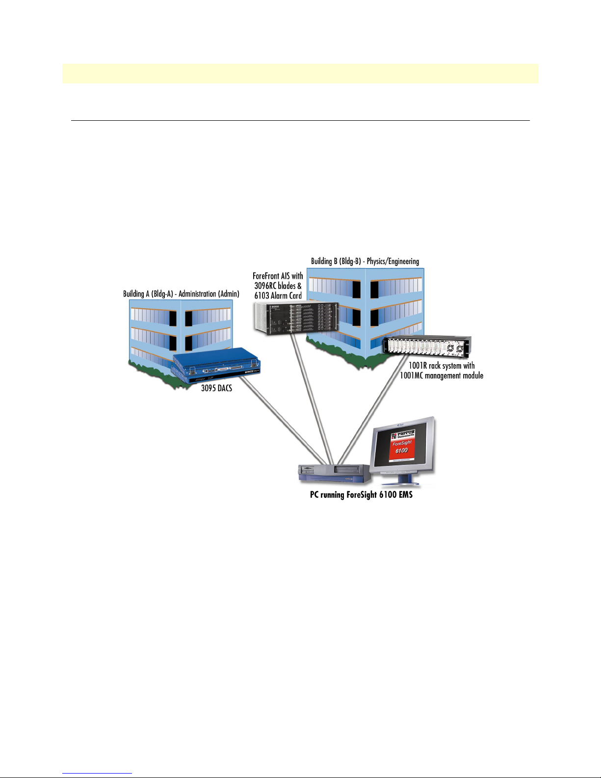
For example, figure 1 shows a campus network comprising a Patton Model 3095 DACS, a ForeFront DSL
access system (fully loaded with 3096RC blades), and a Model 1001R rack system connected to a PC running the ForeSight 6100 EMS.
Figure 1. Sample network
Introduction
Page 11
9
ForeSight 6100 EMS User Guide
1 • ForeSight 6100 EMS overview
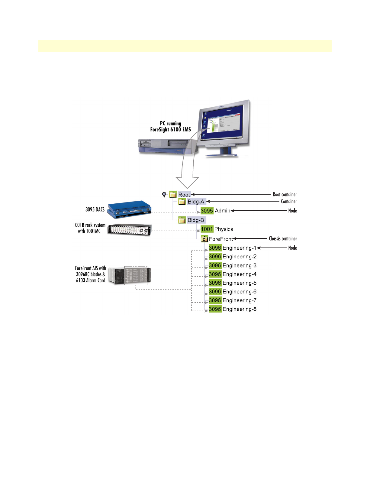
The ForeSight 6100 hierarchical display resembles the example shown in figure 2. The Root , Bldg-A , and Bldg-
B container groupings make it easy to quickly locate the nodes ( 3095–Admin , 1001MC–Physics , 3096RC–
Engineering-1 , etc.).
Nodes
A node represents a simple network management protocol (SNMP)-enabled Patton device (such as a Model 3095
DACS) on the network. Nodes are always created and grouped inside containers.
The ForeSight 6100 EMS polls the nodes for status information and is notified by the nodes when an event
occurs. Common events include an element exceeding a preset threshold, an element changing state, or an
SNMP agent-generated alert that an event has occurred.
The ForeSight 6100 can indicate node status in a variety of ways—including changing the color of the container’s icon or highlighting the node’s text label (in figure 2, for instance, the container icons and node labels
are all colored green, which signifies that everything is functioning normally).
Individual node management takes place outside of the ForeSight 6100 application by using a web browser or
Telnet client. This is done by selecting the desired node from the ForeSight 6100 hierarchical display and
Introduction
Figure 2. Sample ForeSight 6100 display
Page 12

10
1 • ForeSight 6100 EMS overview
ForeSight 6100 EMS User Guide
choosing the web page option from a pop-up menu, in which case a web browser launches and displays the
node’s web page from which it can be managed, or by choosing the Telnet option, which launches the Telnet
client application.
Note
Because of the wide variety of devices that can be managed by the
ForeSight 6100 EMS, this guide does not describe how to configure a
node from its web pages or by using a Telnet client. Instead, refer to
the documentation that came with each device to learn how to configure it via the web or a Telnet interface (or through the device’s console interface, if it is so equipped).
Container types
The ForeSight 6100 uses containers to organize network elements in a way that is easily understood. Containers can hold multiple containers and nodes, as shown in figure 2 on page 9 where the Bldg-B container holds
the 1001MC node and the ForeFront chassis container (which in turn contains several 3096RC nodes). The
ForeSight 6100 uses the following types of containers (see figure 2 on page 9):
• Root container
• Standard container (referred to simply as container )
• Chassis container (ForeFront AIS)
The Root container (see figure 2), the topmost container in the heirarchical tree, always appears when the ForeSight 6100 application is running. There can only be one Root container and it cannot be deleted.
Any container that hold containers is a parent container (the container inside the parent is a child container).
Depending on how it is being considered in the heirarchical tree structure at the time, the same container can
be a parent or a child. For example, as shown in figure 2 on page 9, the container Bldg- B is a child of the Root
container, but Bldg-B is also a parent to the ForeFront container. The Root container is a parent, and it alone
can never be a child because it cannot be placed inside another container.
Containers can be organized as desired, but the most common method is to group them by physical location as
shown in figure 2 on page 9. For example, if you were organizing containers based on the university network
shown in figure 1 on page 8, you could group them by location as follows:
• Building A (Administration), which contains a Model 3095, would be created under Root as container Bldg-
A containing the Model 3095 node named Admin .
• Building B (Physics/Engineering), which contains a 1001 rack in the Physics department and a ForeFront
AIS in the Engineering department, would be created under Root as container Bldg-B. The 1001 rack node
would be a labeled Physics. The 3096RC blades installed in the ForeFront AIS would be shown inside a
chassis container and would be labeled Engineering-1 through Engineering-8.
Note The chassis container is a type of container that is only used with Fore-
Front managed nodes (see section “The Chassis” on page 56).
Introduction
Page 13

ForeSight 6100 EMS User Guide 1 • ForeSight 6100 EMS overview
Compatibility
The Patton ForeSight 6100 EMS can manage up to 200 SNMP-compliant Patton Electronics elements (also
called nodes) that support ForeSight Management Interface Specification (FMIS) standards. These products
currently include:
• 6511RC—ForeFront AIS Matrix Switch with STM-1/OC-3 trunk interface
• 3125RC—ForeFront AIS Remote Access Server Blade provides 96 or 120 ports for dial-up access
• 3120—Remote access server (RAS) provides 30, 60, 96, or 120 ports for dial-up access
• 3096RC—ForeFront AIS Blade that offers G.SHDSL and T1/E1 WAN ports
• 3095—Digital Access and Cross-Connect System (DACS) provides 16 mDSL ports at rates up to
2.3 Mbps and T1/E1 WAN ports
• 2616RC—ForeFront AIS E1/T1 DACS
• 1001MC—SNMP/HTTP Netlink Management Module for Model 1001 rack rack system
Minimum system requirements
An industry-standard PC is required which meets the following minimum specifications:
• Pentium III, 500MHz CPU
• 128 Mbyte RAM
• 35 Mbytes of available disk space for software installation
• Ethernet NIC card
• CD-ROM drive
The following operating systems are supported:
• Windows 98
• Windows NT
• Windows 2000
• Windows XP
• Java 1.4.2 (provided with the ForeSight 6100 EMS)
Compatibility 11
Page 14

1 • ForeSight 6100 EMS overview ForeSight 6100 EMS User Guide
12 Minimum system requirements
Page 15

Chapter 2 ForeSight 6100 EMS installation
Chapter contents
Installation instructions .........................................................................................................................................14
Registration ...........................................................................................................................................................15
13
Page 16
2 • ForeSight 6100 EMS installation ForeSight 6100 EMS User Guide
Installation instructions
Do the following to install the ForeSight 6100 EMS.
1. Insert the CD into your CD drive
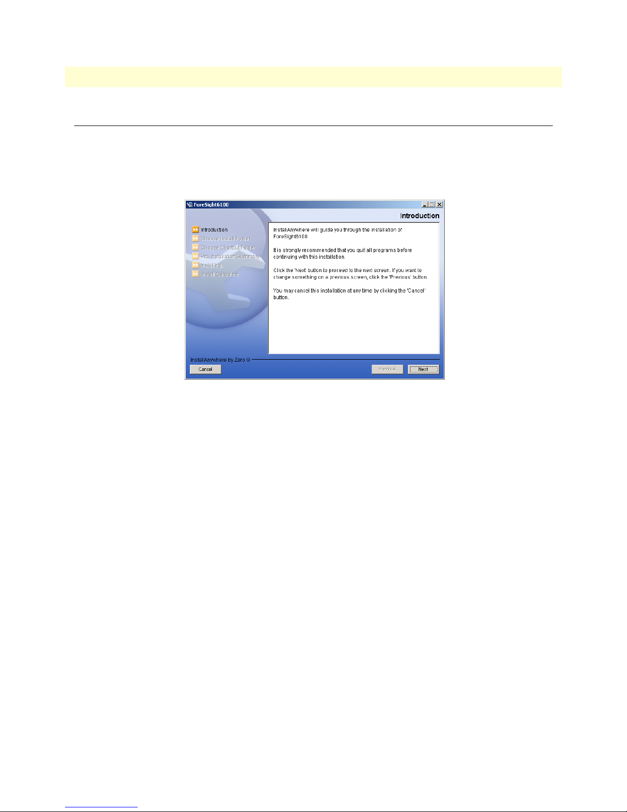
2. The ForeSight 6100 start menu automatically appears (see figure 3).
Figure 3. Introduction window
3. Click the Next button. Continue installing the application by following the displayed instructions.
4. When the installer finishes installing the ForeSight 6100, go to section “Registration” on page 15 in this
guide for instructions on registering your ForeSight 6100 with Patton Electronics Sales.
14 Installation instructions
Page 17
ForeSight 6100 EMS User Guide 2 • ForeSight 6100 EMS installation
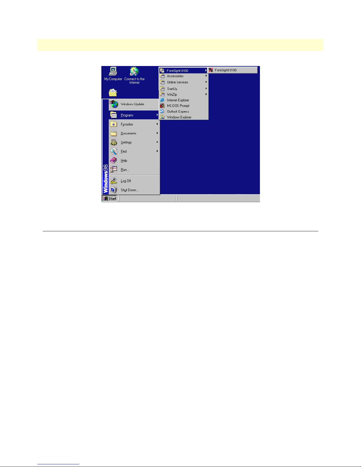
Figure 4. ForeSight 6100 application icon
Registration
To register the ForeSight 6100 EMS, you must obtain a registration file from Patton Electronics Sales by calling +1 (301) 975-1000 or e-mailing sales@patton.com. The Sales Department is available Monday through
Friday, from 8:00 A.M. to 5:00 P.M. EST (8:00 to 17:00 UTC-5).
You will need to provide following information to register your copy of the ForeSight 6100 EMS:
• Your company’s name
• Your name or the name of the registered user
• IP address of the device onto which the ForeSight 6100 will be installed
• MAC address of the device onto which the ForeSight 6100 will be installed
• Operating system (Windows NT, Windows 2000, etc.)
The registration file will be sent to you via e-mail. When it arrives, save the file to a location where it can be
easily found later.
Once you have the registration file, do the following to register the ForeSight 6100:
1. Click on the
run the application.
Start button, then Programs > ForeSight 6100 and select ForeSight 6100 (see figure 4) to
Registration 15
Page 18

2 • ForeSight 6100 EMS installation ForeSight 6100 EMS User Guide
Figure 5. License File window
2. The first time the ForeSight applications runs, it will ask the user to specify the location of the registration
file (see figure 5). Click the
Browse button to find the registration file obtained from Patton Sales.
3. When registration finishes, you will be prompted to restart the ForeSight 6100 application. As the Fore-
Sight 6100 starts (or boots), a splash screen (see figure 6) displays information on operations the EMS is
performing. The splash screen can either be hidden by clicking on it or it will automatically close 5 seconds
after the ForeSight 6100 finishes booting.
Figure 6. Splash screen
Congratulations, your ForeSight 6100 EMS is ready for use! Go to chapter 3, “Getting started” on page 17 to
begin using the 6100 EMS.
16 Registration
Page 19

Chapter 3 Getting started
Chapter contents
Introduction..........................................................................................................................................................18
Creating containers and nodes...............................................................................................................................18
Adding a container ..........................................................................................................................................18
Adding a node (pollable device) ......................................................................................................................20
Configuring a node through the WWW or Telnet ................................................................................................22
Managing events....................................................................................................................................................22
17
Page 20

3 • Getting started ForeSight 6100 EMS User Guide
Introduction
This chapter describes:
• Creating containers and nodes on the ForeSight 6100 to represent your network
• Configuring a node through the WWW or a Telnet client.
• Managing events
Creating containers and nodes
The ForeSight 6100 uses a tree-oriented hierarchical display of nested containers that can be easily navigated to
access different nodes. Nodes—which are SNMP-enabled devices on the network—are always created inside containers. (Examples of nodes would be the Patton Model 3095 and 3096RC blades in a ForeFront AIS.).
Containers can be organized as desired, but the most common method is to group them by physical location
(for instance, in a large network spanning a country, the hierarchical tree could be structured to represent a
country, location, city, site, chassis, device, etc.). The same method can be used for smaller networks, such as,
for example, if you were organizing containers based on the university network shown in figure 1 on page 8,
you could group them by location as follows (see figure 2 on page 9):
• Building A (Administration), which contains a Model 3095RC, would be created under Root as container
Bldg-A containing the Model 3095 node named Admin.
Note The Root container—parent for all other containers—is always
present and cannot be deleted.
• Building B (Physics/Engineering), which contains a 1001 rack in the Physics department and a ForeFront
AIS in the Engineering department, would be created under Root as container Bldg-B. The 1001 rack node
would be a labeled Physics. The 3096RC blades installed in the ForeFront AIS would be shown inside a
chassis container and would be labeled Engineering-1 through Engineering-8 (the chassis container is a type
of container that is only used with ForeFront nodes (see section “The Chassis” on page 56 for details).
Note After a node has been created, the container path for that node is per-
manent and can only be changed by deleting the node and recreating
it in different containers. Therefore, for best results, take a few minutes to work out the desired organization of containers and nodes on
paper before creating nodes and containers in the ForeSight 6100.
Adding a container
You will need the following information before creating a container:
• Parent container name (this is the container into which the new container will be added) (see section “Par-
ent Container” on page 42 for more information)
• Display name (this is the name of the new container as it will appear on the ForeSight 6100 display) (see
section “Display Name” on page 42 for more information)
• Container type (see section “Type” on page 42 for more information)
Optionally, if you will be providing an icon image, have the image ready in in JPEG or GIF format (see section
“Choose Icon” on page 42 for more information)
18 Introduction
Page 21
ForeSight 6100 EMS User Guide 3 • Getting started
In the ForeSight 6100, do the following to add a container:
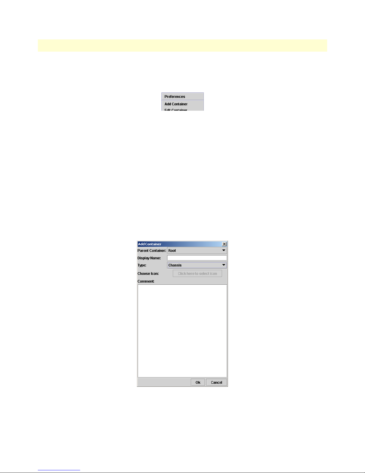
1. Click Edit > Add Container (see figure 7).
Figure 7. Edit > Add Container
2. Select a parent container (see figure 8)—the new container will be created under this container.
Note When the new container has been created, it will automatically be
added to the parent container list as a potential parent for future
nodes and containers.
3. Enter a display name (see figure 8) (this is the name that the ForeSight 6100 displays to the user).
4. Choose a type (see figure 8).
– The Chassis type is used if it is representing a Patton ForeFront rack system. There is some further con-
figuration that is possible after it is added (see section “The Chassis” on page 56).
– The Container logically groups nodes and other containers. Container should always be selected as the
type unless it is representing a Patton ForeFront rack system (in which case the type would be Chassis).
5. Select a device icon (see figure 8 on page 19). If the option Colorize Icon is selected in the Event Manage-
ment tab of the preferences dialog then this option will be disabled. In which case, the ForeSight 6100
will automatically manage the icon.
Creating containers and nodes 19
Figure 8. Add Container window
Page 22

3 • Getting started ForeSight 6100 EMS User Guide
6. Add any comments in the large text area (see figure 8 on page 19).
7. Click the OK button (see figure 8 on page 19) to save the changes.
A container of undefined state has been added under its parent container. The state of the container will be
changed when a node is added to it, and the state of that node is acquired.
Adding a node (pollable device)
You will need the following information before creating a node (also referred to as a pollable device):
• Parent container name (this is the container into which the new node will be added) (see section “Parent
Container” on page 44 for more information)
• Display name (this is the name of the new node as it will appear on the ForeSight 6100 display) (see section
“Display Name” on page 44 for more information)
• IP address (see section “IP Address” on page 45 for more information)
• SNMP community string (an SNMP community string is an unencrypted text string that acts as a pass-
word used to authenticate messages sent between the ForeSight 6100 and the node). Usually, this string
consists of the “read community string” which is the monitor password. Under certain circumstances, however (see section “Choose Proxy” on page 57), it must be the “write” community string, which is the
superuser password.
• Device type (this would be one of the following SNMP-compliant Patton Electronics products that support
the ForeSight Management Interface Specification (FMIS) set of standards):
- 6511RC (ForeFront AIS device)
- 3125RC (ForeFront AIS device)
- 3120 RAS
- 3096RC (ForeFront AIS device)
- 3095 DACS
- 2616RC (ForeFront AIS device)
- 1001MC rack management module
Optionally, if you will be providing an icon image, have the image ready in in JPEG or GIF format (see section
“Choose Icon” on page 45 for more information)
In the ForeSight 6100, do the following to add a pollable device:
1. Click Edit > Add Node (see figure 9).
2. Select a parent container (see figure 10). The new node be created under this container.
20 Creating containers and nodes
Figure 9. Edit > Add Node
Page 23

ForeSight 6100 EMS User Guide 3 • Getting started
3. Enter a display name (see figure 10) (this is the name that the ForeSight 6100 displays to the user).
4. Enter a community string (see figure 10). This is usually the “read” community string (see section “Com-
munity String” on page 45), but in certain circumstances .
5. Select a device type (see figure 10).
Note If the Patton device type is not listed, choose Unknown—the Fore-
Sight 6100 will make a best-effort to operate with the device.
6. If the Choose Icon: option (see figure 10) is enabled, click the menu and select an icon.
Note By default, the option Colorize Icon is selected in the Event Manage-
ment tab of the Preferences dialog, which means that the ForeSight
6100 manages icons; so you will not be able to select a device icon.
7. Add any comments in the large text area (see figure 10 on page 21).
8. Click the OK button (see figure 10 on page 21) to save the changes.
A new node has been added to the tree on the left side of the 6100 with an unknown state. The state of the
newly added device will be acquired during the next polling cycle of the State Poller.
Configuring a node through the WWW or Telnet
To configure a node via a web page or Telnet client, do the following:
1. Select the desired node.
Configuring a node through the WWW or Telnet 21
Figure 10. Add Node window
Page 24

3 • Getting started ForeSight 6100 EMS User Guide
2. If you want to configure the node through the WWW, go to step 3. Otherwise, to use a Telenet client to
configure the node, right-click the mouse and choose the Telnet option. The Telnet client will launch “pre-
loaded” with the IP address of the node. Go to step 4.
3. To configure the node through the WWW, right-click the mouse and choose the Web Page option. A web
browser will launch and display the web page for the selected node.
4. Refer to the refer to the documentation that came with the device for information on configuring it via
the web browser or Telnet client.
Managing events
The ForeSight 6100 indicates the status of nodes on the heirarchical tree by changing the text background
color of node names and the icon color of parent containers (for example, in figure 11 the green icons and text
backgrounds signify that everything is functioning normally).
Figure 11. Sample heirarchical tree
When a node changes state, it generates an alarm, then the node sends an SNMP trap message to the 6100 EMS.
The 6100 EMS changes the node’s color to red, orange, or yellow (depending upon the severity of the alarm), signifying that a major event has occurred, and also changes the icon color for all parent containers to the same color.
22 Managing events
Page 25

ForeSight 6100 EMS User Guide 3 • Getting started
For example, if the Model 3096RC node Lab-1 experiences a main clock failure, the 6100 EMS changes the
icon color and all parent containers to orange upon receiving the SNMP trap for the 3096RC (see figure 12).
Note When a severe event occurs, the ForeSight 6100 will assign that event
color to the node and its parent containers until the event is resolved or a
more severe event occurs. If less severe events at the node are also occurring, they will not be shown (i.e., while a major event is in progress on a
node, a minor event at the same node will not be displayed).
Figure 12. Heirarchical tree showing a major event at node Lab-2
The ForeSight 6100 indicates events by using the colors listed in table 3.
Table 3. Event colors
Event Icon/text background color
Critical Red
Major Orange
Minor Yellow
Clear (normal operation) Green
Informational Blue
When an informational, minor, major, or critical event occurs, the operator should address the problem by first
locating the node sending the event messages. The quickest way is by clicking on containers colored at the
same level of severity until the node is located, then select the node and click on the Events tab in the node’s
panel to see events that have occurred at the node.
Continuing with the example of the 3096RC node with a failed clock, the events listed would resemble those
shown in figure 13. In the figure, node Lab-2 has sent the major severity event trap message: Blade: Main Clock
Fail: Active, meaning that the main clock in Lab-2 has failed. In the next event (event 25), Lab-2 sent the trap
message: Box State Change to Major, which caused the ForeSight 6100 to change Lab-2’s label and parent con-
tainers colors to orange (see figure 12).
Figure 13. Event table showing events of major severity
Managing events 23
Page 26

3 • Getting started ForeSight 6100 EMS User Guide
Having determined what the problem is, the operator would double-click on the Blade: Main Clock Fail: Active
error to display the Event Sub Window (see figure 14), check the ACK box to show that the problem has been
acknowledged, and write a short comment describing what was done about the event (in this case, technical
services was called).
Figure 14. Event Sub Window showing major alarm
Figure 15. Event table after problem has been resolved
Technical services repairs the problem by rebooting the node, at which point the node sends a trap message of
informational severity (see event 26 in figure 15) stating that the node is Rebooting System. This message is followed by event 27: Blade: Main Clock Fail: Inactive, meaning the clock failure has been resolved.
Event 28, Box State Change to Clear, clears away the major event condition, so the ForeSight 6100 changes
the Lab-2 node’s icons and text labels to green, signifying that the node is again operating normally (see
figure 11 on page 22).
24 Managing events
Page 27

Chapter 4 File menu reference
Chapter contents
Introduction..........................................................................................................................................................26
Import Firmware Image.........................................................................................................................................26
Export Events........................................................................................................................................................27
Event Items .....................................................................................................................................................27
Event ID ...................................................................................................................................................27
Event OID ................................................................................................................................................27
Event Value ...............................................................................................................................................28
Event Acknowledgment (ACK) .................................................................................................................28
Event Type (Severity) ................................................................................................................................28
Event Timestamp ......................................................................................................................................28
Node Items .....................................................................................................................................................28
Node Name ..............................................................................................................................................28
Node ID ...................................................................................................................................................28
Node IP ....................................................................................................................................................28
Event ID Range ..............................................................................................................................................29
Save to File/Browse button .............................................................................................................................29
Export All Events...................................................................................................................................................30
Delete All Events ...................................................................................................................................................31
Exit........................................................................................................................................................................31
25
Page 28

4 • File menu reference ForeSight 6100 EMS User Guide
Introduction
The following options are available under the File menu:
• Import Firmware Image —This menu option is used to import firmware images into the ForeSight 6100
EMS for distribution to a selected Patton device on the tree (see page 26 for details)
• Export Events—This menu option (see figure 18) is used to export various event and node items (see
page 27 for details)
• Export All Events—This menu option displays the default “exports” directory (see page 30 for details)
• Delete All Events—This menu item removes all events from the database (see page 30 for details)
• Exit—This menu item will exit you from the ForeSight 6100 application (see page 30 for details)
Figure 16. File menu
Import Firmware Image
The Import Firmware menu option is used to import firmware images into the ForeSight 6100 EMS for distri-
bution to a selected Patton device on the tree. Firmware image names must be unique and are based on a combination of the node type and version strings (software version number). For example, there can be any
number of version “1.1.1” as long as each is for a different node type.
Note The 6100 stores the path to the specified file, not the file itself, so
changing the location of the specified file after the 6100 has saved the
path to it can cause firmware updates to fail.
Figure 17. Import Firmware dialog
26 Introduction
Page 29

ForeSight 6100 EMS User Guide 4 • File menu reference
Figure 18. Export Events dialog
Export Events
The Export Events dialog (see figure 18) is used to export a record of event and node items that have occurred
on the network. The exported file, data is saved to a comma-separated-values (CSV) format file, so you can
reuse the event data in a database or spreadsheet program. As shown in figure 18, the exported data can be customized by selecting just the items of interest. The following sections describe the Export Events dialog options.
Event Items
The Event Items section of the Export Events dialog (see figure 19) has the following items that determine how
much detail about each event is included in the exported file. Checked items are saved to the file.
Figure 19. Export Events dialog—Event Items section
Event ID
The unique ID of the event
Event OID
If an event is generated through SNMP, the Event OID is the object identifier (OID) assigned to the event.
Otherwise, a short text description will be assigned.
Event Value
The reason for the event in text.
Event Acknowledgment
Indication of whether the event was acknowledged by the ForeSight 6100 operator.
Event Type
The severity of the event.
Event Timestamp
The time when the event occurred.
Export Events 27
Page 30

4 • File menu reference ForeSight 6100 EMS User Guide
Node Items
The Node Items section of the Export Events dialog (see figure 20) has the following items that determine how
much detail about a reporting node is included in the exported file. Checked items are saved to the file.
Figure 20. Export Events dialog—Node Items section
Node Name
The name of the node.
Node ID
The unique ID for the node that generated the event (in case there are mutiple nodes with the same node
name).
Node IP
The IP address of the node.
Event ID Range
The Event ID Range section of the Export Events dialog (see figure 21)enables you to choose to export some or
all events as determined by the range of event IDs.
Figure 21. Export Events dialog—Event ID Range section
To export some of the events, (for example all events from 100 to 1000), you would type 100 in the From box
and 1000 in the To box.
A quicker way to specify large ranges of events is to use the 0 (zero). Using a 0 in the From box tells the ForeSight 6100 to export all events from 1 up to the number in the To box (for example, a range of From 0 To 1,000
would export events 1–1,000). Using a 0 in the To box exports all events starting from the number in the From
box (for example, if there were 5,000 events stored, a range of From 1000 To 0 would export events 1,000–
5,000). To export all stored events, set a range of From 0 To 0.
Save to File/Browse button
The Save to File of the Export Events dialog (see figure 22) is where you can type the directory path to where the
exported file is to be saved and the file name. The file will be saved as a comma-separated-values (CSV) format
file, so you can reuse the event data in other applications.
Figure 22. Export Events dialog—Save to File section
28 Export Events
Page 31

ForeSight 6100 EMS User Guide 4 • File menu reference
Note In a CSV-formatted file, each line (or row) of data in the file con-
sists of one record, and each field of the record is separated by commas. CSV files can easily be transferred into spreadsheet and
database applications.
Note You must include the .csv extension in the file name. If “.csv” is left
off the file name it will not be automatically added.
Figure 23. Save dialog
A faster way of specifying the directory path than typing it out is to click on the Browse button, which displays
the Save dialog (see figure 23). Select the directory where you want the file saved, then type the file name in the
File Name box. If you are saving a file for the first time, type the name of the new file, or—if you are overwriting an existing file—click on a previously saved file to overwrite.
There will be no warning if you type a file name that is the same
as a file name already in the directory; so unless you want to
overwrite an existing file, make sure the name you choose isn’t
in the directory! You will not be able to recover a file overwritten
by mistake.
Click the
Save button to to complete the save operation or click the Cancel button to cancel without saving.
Export Events 29
Page 32

4 • File menu reference ForeSight 6100 EMS User Guide
Export All Events
The Export All Events menu item (see figure 16 on page 26) displays the Save dialog (see figure 24) where you
can export event data to a comma-separated-values (CSV) format file, so you can reuse the event data in other
applications. The Export All Events menu option opens a dialog box displaying the contents of the default
“exports” directory (<install>/exports). By default, only previously saved CSV files are shown. If you are saving a
file for the first time, type the name of the new file, or—if you are overwriting an existing file—click on a previously saved file to overwrite.
Figure 24. Export All Events dialog
Be careful when selecting a file to overwrite that you select the
correct file! There will be no warning when you click the Save
button to overwrite a file and you will not be able to recover a
file overwritten by mistake.
Note In a CSV-formatted file, each line (or row) of data in the file consists
of one record, and each field of the record is separated by commas.
CSV files can easily be transferred into spreadsheet and database
applications.
Note You must include the .csv extension in the file name. If “.csv” is left
off the file name it will not be automatically added.
Delete All Events
Selecting the Delete All Events menu item (see figure 16 on page 26) removes all events from the database.
Exit
Select the Exit menu item (see figure 16 on page 26) to exit from the ForeSight 6100 application.
30 Export All Events
Page 33

Chapter 5 Edit menu reference
Chapter contents
Introduction..........................................................................................................................................................33
Preference tabs.......................................................................................................................................................33
General Options .............................................................................................................................................34
Error Log ..................................................................................................................................................34
Web-browser .............................................................................................................................................34
Database Manager .....................................................................................................................................34
Telnet Client .............................................................................................................................................34
Poller Options ................................................................................................................................................34
Timeout ....................................................................................................................................................35
Retries .......................................................................................................................................................35
Cache ........................................................................................................................................................35
Interval ......................................................................................................................................................35
Event Management .........................................................................................................................................36
Database Limit ..........................................................................................................................................36
Display Limit ............................................................................................................................................36
Store Events Only on State Change ...........................................................................................................36
Colorized Icon (Using Type Specific Icon) ................................................................................................37
Colorized Text Background ......................................................................................................................37
Email Notification ..........................................................................................................................................37
Email Server ..............................................................................................................................................37
Monitor’s Email ........................................................................................................................................38
Edit Email List ..........................................................................................................................................38
Enable Authentication ...............................................................................................................................38
Database Options ...........................................................................................................................................39
Database Name .........................................................................................................................................39
Driver Name .............................................................................................................................................39
Username ..................................................................................................................................................39
Password ...................................................................................................................................................39
Test Connection .......................................................................................................................................39
Auto-Config Push (ACP) options ...................................................................................................................40
Automatic Push .........................................................................................................................................40
Prompt for Push ........................................................................................................................................40
Prompt User (No Push) ............................................................................................................................41
Ignore Push ...............................................................................................................................................41
Add Container.......................................................................................................................................................41
Parent Container .............................................................................................................................................42
Display Name .................................................................................................................................................42
Type ...............................................................................................................................................................42
Choose Icon ....................................................................................................................................................42
31
Page 34

5 • Edit menu reference ForeSight 6100 EMS User Guide
Comment .......................................................................................................................................................42
Edit Container.......................................................................................................................................................43
Selected Container ..........................................................................................................................................43
Parent Container .............................................................................................................................................43
Display Name .................................................................................................................................................43
Type ...............................................................................................................................................................43
Choose Icon ....................................................................................................................................................44
Comment .......................................................................................................................................................44
Add Node..............................................................................................................................................................44
Parent Container .............................................................................................................................................44
Display Name .................................................................................................................................................44
IP Address .......................................................................................................................................................45
Community String ..........................................................................................................................................45
Type ...............................................................................................................................................................45
Choose Icon ....................................................................................................................................................45
Comment .......................................................................................................................................................45
Edit Node..............................................................................................................................................................45
Database Manager .................................................................................................................................................45
Start State Polling..................................................................................................................................................45
32
Page 35

ForeSight 6100 EMS User Guide 5 • Edit menu reference
Introduction
The following options are available under the Edit menu (see figure 25):
• Preferences—Global options are set through the use of the Preferences dialog (see page 33 for details)
• Add Container—A container can be added from the Add Container dialog (see page 41 for details)
• Edit Container—A container can be modified from the Edit Container dialog (see page 43 for details)
• Add Node—A node can be added from the Add Node dialog (see page 44 for details)
• Edit Node—A node can be modified from the Edit Node dialog (see page 45 for details)
• Database Manager—This executes a database manager (see page 45 for details)
• Start State Polling—This check box toggle state polling on and off (see page 45 for details)
Figure 25. Edit menu
Preference tabs
Global options are set through the use of the Preferences dialog (see figure 26). The Database Options tab con-
trols connection to an internal database—these are advanced options and should be changed with great care.
The other tabs—General Options, Poller Options, Auto-Config Push Options, Email Notification, and Event Man-
agement—control options that can be edited for operation without adversely impacting operation.
Figure 26. Preferences dialog
Introduction 33
Page 36

5 • Edit menu reference ForeSight 6100 EMS User Guide
General Options
The General Options tab (see figure 26) enables a user to define the Error Log, Web Browser, Database Manager,
and the Telnet Client.
Error Log
This is the filename that will be used when the ForeSight 6100 saves error messages. In the event of a major
error (the ForeSight 6100 application exiting unexpectedly, for example) error messages will be written to the
error log file.
Web-browser
This text field contains the file path to the web browser that will be used (for example, in figure 26 on page 33,
the path is C:\Program Files\Internet Explorer\IEXPLORE.EXE). The default web browser for Windows is Inter-
net Explorer
Database Manager
This text field contains the file path to an external database manager. If the system is using the internal database, no database manager should be defined because as there is no manager for it, other than the 6100 EMS.
If no executable is specified here, then Edit > Database Manager will do nothing.
Telnet Client
This text field contains the command to launch a Telnet client. The default utility for Telnet is Telnet Interface.
Note In Windows 98, the field must be specified as telnet. In Windows
2000 and Windows XP, the Telnet Client field must be specified as
cmd/c start telnet (see figure 26 on page 33).
Figure 27. Poller Options dialog
Poller Options
The Poller Options tab (see figure 27) enables the user to configure the following polling parameters:
• Timeout setting (see section “Timeout” on page 35)
• Retries setting (see section “Retries” on page 35)
• Cache setting (see section “Cache” on page 35)
34 Preference tabs
Page 37

ForeSight 6100 EMS User Guide 5 • Edit menu reference
• Interval setting (see section “Interval” on page 35)
Figure 28. State Poller indicator
Note There is also a State Poller indicator located in the opening screen of
the ForeSight 6100 EMS in the top right corner (see figure 28). State
Poller indications are defined in table 4.
Table 4. State Poller indications
State Action Color Icon
Polling Sending SNMP GET requests Yellow
Waiting Waiting for SNMP GET responses Green
Stopped Doing nothing Red
Timeout
This value is the SNMP packets time-to-live (TTL). It is the number of seconds to wait for a packet before
considering it dead. Generally a setting of 1 or 2 seconds is appropriate, but for congested networks, higher values are recommended. The range is 1–1000 seconds; the default value is 1 second.
Retries
This value is the number of times for the ForeSight 6100 to retry SNMP polling if a response is not received
before timeout. The range is 0–1000 retries; the default value is 0 retries.
Cache
This setting is the number of milliseconds that a valid SNMP response will be cached in memory, which helps
prevent network flooding. The range is 0–1000 milliseconds; the default value is 0 milliseconds.
Interval
This setting is the amount of time in minutes that the 6100 EMS will wait between two successive polls to the
same box. The range is 0–1000 minutes; the default value is 2 minutes.
Note The value assigned to Interval must be a higher number than the
result of Timeout multiplied by Retries values. In other words,
Interval > (Timeout X Retries)).
Preference tabs 35
Page 38

5 • Edit menu reference ForeSight 6100 EMS User Guide
Figure 29. Event Management dialog
Event Management
The Event Management dialog (see figure 29) is for configuring:
• The maximum number of events allowed in the database (see section “Database Limit”)
• The number of events any single event table will show
• Whether the 6100 EMS will add an event every time a poll returns
• Whether to colorize the icons and text background as indicators of state changes
Database Limit
This option defines the maximum number of events allowed in the database. If more events are recorded after
the limit is reached, the oldest events are deleted to make room for new ones. The value 0 means no limit. A
value of 20,000 is generally sufficient. The default is 10,000.
Note There is no warning message before old events are overwritten.
Display Limit
This option defines the number of events that any single event table will show. After this limit is reached old
events will not be displayed. A value of 0 means no limit. A value of 1,000 is generally sufficient. The default
is 1,000.
Store Events Only on State Change
When this option is checked, the 6100 EMS will not add new events every time a poll returns. New events will
only be added if there is a state change.
Note This setting only pertains to polled events, all external and internal
traps will be saved. Traps from external sources—such as SNMP
agent-generated traps—will be stored (including those with no state
change). Internally generated ForeSight 6100 administrative traps
will also be stored, regardless of whether the Store Events Only on State
Change option is checked.
36 Preference tabs
Page 39

ForeSight 6100 EMS User Guide 5 • Edit menu reference
Colorized Icon (Using Type Specific Icon)
This option configures the 6100 EMS to colorize the icons to indicate a state change (see figure 30). Because of
the complexity involved in determining state, ForeSight has internally defined icons for every state of every
node type (including containers and folders). ForeSight then displays the appropriate icon for each node, based
on its current state.
Figure 30. Colorized icons
Note Since a tree can only display one icon per node, the colorized icon
takes precedence over the user-defined icon.
Colorized Text Background
When this option is checked, the ForeSight 6100 will colorize the text background based on the state of the
network device (see figure 31). When this is not checked, no background color is used.
Figure 31. Colorized text background, no colorized icon
Email Notification
Click on the Email Notification tab, then the Enable Email Notification check box (see figure 32) to enable the
6100 EMS to send email upon receiving an event.
Figure 32. Email Notification dialog
Email Server
This is the URL of the email server to send messages through (for example, xxxx.yourdomain.com)
Preference tabs 37
Page 40

5 • Edit menu reference ForeSight 6100 EMS User Guide
Monitor’s Email
This is the email address to place in the “From” section of an email. It is specified just in case email messages
are bounced back. If this happens, the bounced messages will be placed in the mailbox for the specified email
address. Only one monitor email address can be specified. (for example, 6100@yourdomain.com)
Figure 33. Email List dialog
Edit Email List
Click on the Edit email list button to display the Email List dialog box (see figure 33). This is where email messages that go in the “To” section of an email are specified, there can be multiple addresses. To specify an email,
right click the
Add New Email button. The Notification Options window (see figure 34) will be displayed allow-
ing for the addition of a new email address. The check boxes indicate what kind of events are to be sent to the
specified email address. At least one of the check boxes must be checked for the email address to be added to
the list.
Enable Authentication
If the specified email server requires authentication for sending email messages, click this check box to enable
authentication. Also add the required username and password to allow for logging in.
38 Preference tabs
Figure 34. Notification Options dialog
Page 41

ForeSight 6100 EMS User Guide 5 • Edit menu reference
Database Options
This dialog box is where you can change the database configuration if you are going to be using a database
other than the one provided with the ForeSight 6100 EMS.
Using a database other than the one provided with the ForeSight
6100 requires advanced knowledge that is beyond the scope of
this guide. At a minimum, any replacement database must be
Java DataBase Connectivity (JDBC) compliant (JDBC is the standardized database interface for Java).
For more information about JDBC, refer to the frequently asked
questions (FAQ) document at:
http://java.sun.com/products/jdbc/reference/faqs/index.html
Figure 35. Database Options dialog
Database Name
This is the name of the database that the ForeSight 6100 will be using. The database name syntax is determined by the JDBC driver being used to connect to the database. Consult the documentation that came with
the JDBC driver for valid names.
Driver Name
This is the Java standard class-path to the class that contains the driver. The driver must adhere to the JDBC standard. Generally a driver class is included with the connecting database, and it must exist in the 6100’s class path.
Since the user is unable to change the classpath, this driver must be a single file under the installed 6100 directory.
Username
This is the JDBC driver-specified username that is used to log on to the database.
Password
This is the password for the user.
Test Connection
This button is used to close the current database connection and open a new connection. The status of the
connection is display in the bordered label next to it.
Preference tabs 39
Page 42

5 • Edit menu reference ForeSight 6100 EMS User Guide
Auto-Config Push (ACP) options
The auto-configuration push (ACP) capability enables the ForeSight 6100 to detect and respond to changes in
a node that result from installing the node in a new location or replacing the node. When the ForeSight 6100
detects such changes, ACP can respond by installing (pushing) a new node configuration consistent with the
new physical location of the element (one that takes into account that the node is in a different slot in a chassis,
for example). ACP can be configured to operate under varying levels of constraint:
• Automatic Push—The push operation takes place without user intervention (see section “Automatic Push”)
• Prompt for Push—The push operation will take place as soon as the user approves (see section “Prompt for
Push”)
• Prompt User (No Push)—The ACP function has been disabled, but it will still notify a user that an ACP
situation has been detected (see section “Prompt User (No Push)” on page 41)
• Ignore Push—ACP is disabled and no notice will be given if an ACP situation occurs (see section “Ignore
Push” on page 41)
The Auto-Config Push Options tab (see figure 36) tells the ForeSight 6100 how to deal with ACP situations. This
only affects what the 6100 does if it senses the need for a push; it will not shut-down the sensing mechanism.
Automatic Push
Upon detecting an ACP situation, the ForeSight 6100 will perform a push operation without user approval. Indication messages are stored in the event table for accounting purposes but no other indications will be made.
Prompt for Push
Upon detecting an ACP situation, the ForeSight 6100 will prompt the user for approval before performing a push
operation (see figure 37) . If the user responds by clicking on the
40 Preference tabs
Figure 36. Auto-Config Push Options dialog
No button, the push operation is cancelled.
Figure 37. Auto-Config Push indication
Page 43

ForeSight 6100 EMS User Guide 5 • Edit menu reference
Prompt User (No Push)
This setting disables ForeSight 6100’s ability to perform a push operation (see figure 38). It simply notifies a
user that an ACP situation has been detected. The user must then take the appropriate steps to install a new
configuration on the changed node.
Figure 38. Auto-Config Push Indication
Ignore Push
This setting disables ACP completely. If a situation occurs that would normally have been detected by the ACP
function, the ForeSight 6100 user must detect it unaided and then take the appropriate steps to install a new
configuration on the changed node.
Add Container
A container can be added from the Add Container dialog (see figure 39) on the Edit Menu or by right-clicking
a container in the heirarchical tree.
Add Container 41
Figure 39. Add container dialog
Page 44

5 • Edit menu reference ForeSight 6100 EMS User Guide
Parent Container
When a container is created, it will always be inside another container. In other words, the newly created container is a child of the parent container. The Parent Container menu is where you choose the parent container
of the newly created container.
Note If a container is being added from the right-click menu, this option
will be disabled.
Display Name
This is the node name displayed on the management tree view.
Figure 40. Container types
Type
There are two types of containers available for use (see figure 40): normal containers, which are capable of
holding nodes as well as other containers, and chassis containers. Chassis containers are only assigned to ForeFront chassis because they can control the optional Model 6103 alarm card installed in a ForeFront chassis.
Choose Icon
This button allows the user to select an image to display along with the name on the tree. It can be in either
GIF or JPEG format and of any size (16 high x 16 wide or 32 high x 32 wide pixel size is recommended).
Note The image will not be resized, so large or odd-sized images should be
avoided. The type specific icon for a container cannot be changed; it
is always a folder icon with a colored background. Also, if the tool is
using type specific icons this option will be disabled.
Comment
This area is used for adding notes and comments.
42 Add Container
Page 45

ForeSight 6100 EMS User Guide 5 • Edit menu reference
Figure 41. Edit Container dialog
Edit Container
The Edit Container dialog enables a user to modify a selected container.
Selected Container
This is a drop down box that allows the selection of the proper container to edit. If this dialog is opened
through the right-click menu this option will be disabled, and the currently selected container will be selected.
Parent Container
When a container is created, it will always be inside another container. In other words, the newly created container is a child of the parent container. The Parent Container menu lets you choose the parent container. If a
container is being added from the right-click menu this option will be disabled.
Display Name
This is the container name displayed on the management tree view.
Type
There are two types of containers available for use (see figure 40 on page 42): standard containers that are capable
of holding nodes as well as other containers, and chassis containers. Chassis containers are only assigned to ForeFront chassis because they can control the optional Model 6103 alarm card installed in a ForeFront chassis.
Edit Container 43
Page 46

5 • Edit menu reference ForeSight 6100 EMS User Guide
Choose Icon
This button allows the user to select an image to display along with the name on the tree. It can be in either
GIF or JPEG format and of any size (16 high x 16 wide or 32 high x 32 wide pixel size is recommended).
Note The image will not be resized, so large or odd-sized images should be
avoided. The type specific icon for a container cannot be changed; it
is always a folder icon with a colored background. Also, if the tool is
using type specific icons this option will be disabled.
Comment
This area is used for adding notes and comments.
Add Node
The Add Node dialog (see figure 42) enables a user to create a node.
Parent Container
When a node is created, it will always be inside a container. The Parent Container menu lets you choose the
container. If a container is being added from the right-click menu this option will be disabled.
Display Name
This is the node name displayed on the management tree view.
44 Add Node
Figure 42. Add Node dialog
Page 47

ForeSight 6100 EMS User Guide 5 • Edit menu reference
IP Address
This must be a valid IP address and it must be unique.
Note The format of the IP address is not tested when it is added to the
database, but later operations will fail if the IP address is not correct.
Community String
This is the SNMP community string for the node. Generally it is the “read” community string which can be
the monitor or superuser password.
Type
This drop down determines how the ForeSight treats this node. The only visible effects of this are: the colorized
icon that will display the node type and the available firmware will be specific to entries for this node’s type.
Choose Icon
This button allows the user to select an image to display along with the name on the tree. It can be in either
GIF or JPEG format and of any size (16 high x 16 wide or 32 high x 32 wide pixel size is recommended).
Note The image will not be resized, so large or odd-sized images should be
avoided. The type specific icon for a container cannot be changed; it
is always a folder icon with a colored background. Also, if the tool is
using type specific icons this option will be disabled.
Comment
This area is used for adding notes and comments.
Edit Node
The Edit Node dialog enables a user to modify a selected node; its options are the same as the Add Node dialog,
so refer to section “Add Node” on page 44 for details.
Database Manager
This executes a database manager (specified in the preferences page). In normal operations (with the embedded
database) there is no manager for the database. This option is provided for advanced users using external databases.
Start State Polling
This check box toggles the polling on or off. When checked, polling takes place. The state poller also affects the
Polling Indicator.
Edit Node 45
Page 48

5 • Edit menu reference ForeSight 6100 EMS User Guide
46 Start State Polling
Page 49

Chapter 6 View menu reference
Chapter contents
Introduction..........................................................................................................................................................48
Event Table ...........................................................................................................................................................48
Event Sub Window .........................................................................................................................................49
Refresh Tree ..........................................................................................................................................................50
Expand all Branches ..............................................................................................................................................50
Collapse all Branches .............................................................................................................................................50
47
Page 50

6 • View menu reference ForeSight 6100 EMS User Guide
Introduction
The following options are available under the View menu (see figure 43):
• Event Table—This is the global event table. It displays the newest events from all nodes (see page 48 for
details)
• Refresh Tree—This menu option causes the entire tree to refresh (including state) (see page 50 for details)
• Expand All Branches—This menu option causes all the branches of the tree to expand (see page 50 for
details)
• Collapse All Branches—This menu option causes all the branches (except the root) to collapse (see page 50
for details)
Figure 43. View Menu
Event Table
This is the global event table. It displays the newest events from all nodes. It can only display as many events as
were specified in the preferences page.
Note All tables can be sorted per column by clicking the column header. A
reverse sort can be done by <shift>-clicking the column header.
Figure 44. Event Table dialog
The table displays the following information:
• Severity—The severity of the event. The different levels of severity are: critical, major, and minor
• Event—The unique ID of the event
• Node—The node name of the device reporting the event
• IP Address—The IP address of the node
• ACK—Indicates whether the event was acknowledged (ACK) by the ForeSight 6100 operator. To acknowl-
edge an event, select the desired event in the table, then double-click it to display the Event Sub Window (see
section “Event Sub Window” on page 49).
48 Introduction
Page 51

ForeSight 6100 EMS User Guide 6 • View menu reference
• OID—If an event is generated through SNMP, the OID is the object identifier (OID) assigned to the event.
Otherwise, a short text description will be assigned
• Trap Value—The reason for the event in text
• Date/Time—The time when the event occurred
• Comment—Displays notes or comments added to the event. To add comments to an event, select the
desired event in the table, then double-click it to display the Event Sub Window (see section “Event Sub
Window” on page 49)
Figure 45. Event Sub Window dialog
Event Sub Window
Double clicking any row on the event table displays the Event Sub Window is where you can add comments to
an event and acknowledge that you have seen the event (useful when managing events as described in section
“Managing events” on page 22). The Event Sub Window displays the following information (see figure 45):
• Severity—The severity of the event. The different levels of severity are: critical, major, and minor
• Node—The node name of the device reporting the event
• Event—The unique ID of the event
• IP Address—The IP address of the node
• OID—If an event is generated through SNMP, the OID is the object identifier (OID) assigned to the event.
Otherwise, a short text description will be assigned
• Trap Value—The reason for the event in text
• Date/Time—The time when the event occurred
• ACK—Checkbox where the ForeSight 6100 operator can acknowledge having seen the event
• Comment—This area is used for adding notes and comments
Event Table 49
Page 52

6 • View menu reference ForeSight 6100 EMS User Guide
Note The global Event Sub Window is the only place where an event’s com-
ment can be edited.
To display other events in the event table, click the
Previous button to display the previous event or the Next
button to display the next event in the table.
When you are finished with the event in the Event Sub Window, click the
have made or click the
Close button to close the window without saving changes.
Apply button to save any changes you
Refresh Tree
This menu option causes the entire tree to refresh (including state). Also, the state poller is reset to force a poll.
Expand all Branches
This menu option causes all the branches of the tree to expand, displaying all nodes and containers.
Collapse all Branches
This menu option causes all the branches (except for Root and the child containers directly under it) to collapse.
50 Refresh Tree
Page 53

Chapter 7 Help menu reference
Chapter contents
Introduction..........................................................................................................................................................52
User Manual..........................................................................................................................................................52
Patton Home Page.................................................................................................................................................52
About ....................................................................................................................................................................52
51
Page 54

7 • Help menu reference ForeSight 6100 EMS User Guide
Introduction
The following options are available under the Help menu (see figure 46):
• Online access to the Getting Started Guide (see section “User Manual”)
• Patton Home Page (see section “Patton Home Page”)
• About (see section “About”)
Figure 46. Help Menu
User Manual
Selecting the User Manual menu option causes the Getting Started Guide you are currently reading to be displayed online in portable document format (PDF).
Patton Home Page
Selecting the Patton Home Page menu option causes a web browser to open and display the Patton Electronics
home page at http://www.patton.com.
About
Selecting the About menu option displays ForeSight 6100 EMS version information.
52 Introduction
Page 55

Chapter 8 Tree structure reference
Chapter contents
Introduction..........................................................................................................................................................54
Containers.............................................................................................................................................................54
Container’s right-click menu ...........................................................................................................................55
Edit option ................................................................................................................................................55
Remove option ..........................................................................................................................................55
Add Container Here option ......................................................................................................................55
Add Node Here option .............................................................................................................................55
Container panel ..............................................................................................................................................56
Name ........................................................................................................................................................56
Worst child severity ...................................................................................................................................56
Comment ..................................................................................................................................................56
Disable Severity Propagation .....................................................................................................................56
The Chassis ...........................................................................................................................................................56
Proxy Information ..........................................................................................................................................57
Choose Proxy ............................................................................................................................................57
Chassis Level Events ........................................................................................................................................57
The Node..............................................................................................................................................................58
Node’s right-click menu ..................................................................................................................................58
Edit option ................................................................................................................................................58
Remove option ..........................................................................................................................................58
Web Page option .......................................................................................................................................58
Telnet option ............................................................................................................................................58
Node panel .....................................................................................................................................................59
General Information .................................................................................................................................59
Events .......................................................................................................................................................60
Configuration ...........................................................................................................................................60
Firmware ...................................................................................................................................................61
Auto-Config Push .....................................................................................................................................62
Options............................................................................................................................................... 62
Configuration...................................................................................................................................... 63
53
Page 56

8 • Tree structure reference ForeSight 6100 EMS User Guide
Introduction
The tree displays a hierarchical view of the managed network. The tree is divided into containers and nodes.
The actual tree appearance depends on options selected in the Preferences dialog. Figure 47 is an example with
the colorized icons turned on (see section “Colorized Icon (Using Type Specific Icon)” on page 37), and col-
orized text background turned off (see “Colorized Text Background” on page 37).
Figure 47. Tree structure
Containers
In the ForeSight 6100 EMS, containers are used to group and organize nodes. Moreover, the color of the icon or
text background for the container indicates the state of the node with the most severe error condition.
For example, figure 48 shows a campus network comprising a Patton Model 3095 DACS, a ForeFront AIS
(fully loaded with 3096RC blades), and two 1001R rack systems connected to a PC running the 6100 EMS.
54 Introduction
Figure 48. Sample network
Page 57

ForeSight 6100 EMS User Guide 8 • Tree structure reference
An error at one of the ForeFront 3096RC blades in Building C would be displayed on the ForeSight 6100 EMS
as shown in figure 49 (assuming that both colorized icons and text background options have been enabled). The
Root, Bldg-C, and ForeFront parent containers would be colored red to indicate a problem with a child.
Figure 49. Sample ForeSight 6100 display
Container’s right-click menu
The right-click menu of a container displays the following options for manipulating the container.
Edit option
Selecting the Edit option displays the Edit Container dialog which enables a user to modify a selected container
(see section “Edit Container” on page 43 for details).
Figure 50. Container context-sensitive menu
Remove option
Remove is used to delete the selected container, as well as its children. Root is the only container that cannot
be removed.
Add Container Here option
Selecting the Add Container Here option displays the Add Container dialog so you can create a container at the
current location (see section “Add Container” on page 41 for more details).
Add Node Here option
Selecting the Add Node Here option displays the Add Node dialog so you can create a node at the current loca-
tion (see section “Add Node” on page 44 for more details).
Containers 55
Page 58

8 • Tree structure reference ForeSight 6100 EMS User Guide
Container panel
The container panel, labeled General Information, provides information on the selected container as well as
items that affect the general state of the container.
Name
The name of the container.
Worst child severity
The state of the child with the most severe error state.
Comment
Displays the contents of the comments box entered in the Add Container (see section “Comment” on page 42)
or Edit Container (see section “Comment” on page 44) dialog boxes.
Disable Severity Propagation
Selecting Disable Severity Propagation prevents this container from informing its parent container of its current
severity. Re-Enable Propagation on Severity Change causes Disable Severity Propagation to be turned off if the
state changes.
Figure 51. Container’s center panel
The Chassis
A chassis container has added capability to communicate with the Model 6103 alarm card in a ForeFront chassis. Because the alarm card has no IP communication capability, it requires a proxy that will intercept its communications and pass them on to the ForeSight 6100 via IP. Currently, only the Patton Model 3096RC can be
used in this proxy role.
Note The ForeSight 6100 makes the assumption that its chassis are set up
exactly like their real world counterparts.
56 The Chassis
Page 59

ForeSight 6100 EMS User Guide 8 • Tree structure reference
Proxy Information
The Proxy Information tab (see figure 52) enables the user to determine which device in the chassis will be used
as the alarm card proxy. Proxy Information dialog is already configured with a different proxy device, it must be
deleted by clicking the
Clear Proxy button before another can take is place. After a proxy device has been
selected, the ForeSight 6100 will automatically configure it to communicate with the alarm card.
Figure 52. Proxy Information dialog
Choose Proxy
When choosing a proxy, the Choose Proxy dialog box (see figure 53) will be displayed. Only devices capable of
communication with the 6103 alarm card will be shown in the list (currently only the Patton Model 3096RC
has this capability). There must be at least one Model 3096RC blade in the chassis to act as a proxy for the
Model 6103 alarm card.
Note The device chosen as the proxy must have as its community string the
“write” community string (that is, the superuser password).
Figure 53. Choose Proxy dialog
Chassis Level Events
A proxy relays events from the 6103 alarm card to the ForeSight 6100. These events originate from the sending
3096RC but are specially formatted to indicate the fact they originate from the alarm card. Any events originating from an alarm card will be displayed on this Chassis Level Events tab (see figure 54). The events table
looks identical to all others in the system except that it only displays chassis-level events.
The Chassis 57
Figure 54. Chassis Level Events table
Page 60

8 • Tree structure reference ForeSight 6100 EMS User Guide
The Node
A node is an SNMP-enabled ForeFront Management Interface Specification (FMIS) compliant device (such as
a Model 3095 DACS) on the network.
Node’s right-click menu
The right-click menu of a node displays the following options for manipulating the node.
Figure 55. Node context-sensitive menu
Edit option
Selecting the Edit option displays the Edit Node dialog which enables a user to modify a selected node (see section “Edit Node” on page 45 for details).
Remove option
Remove is used to delete the selected node.
Web Page option
Selecting the Web Page option starts a web browser and causes it display the web page at the IP address of the
selected node.
Telnet option
Selecting the Telnet option starts a telnet client pointed at the node
58 The Node
Page 61

ForeSight 6100 EMS User Guide 8 • Tree structure reference
Figure 56. Node center panel
Node panel
The node panel (see figure 56) contains the following tabs:
• General information—Contains general information about the node as well as items that affect the general
state of the node (see section “General Information” for more details)
• Events—Displays the events for the selected node (see section “Events” on page 60 for more details)
• Configuration—The configuration of Patton devices is shown on this tab (see “Configuration” on page 60
for more details)
• Firmware—Firmware images for the selected box are listed on this tab (see “Firmware” on page 61 for
details)
• Auto-Config Push (ACP)—This tab controls how a specific node deals with ACP situations (see “Auto-
Config Push” on page 62 for details)
General Information
As the name implies, General Information is displayed on this page, as well as items that affect the general state
of the box. Disable E-mail Notification causes the ForeSight 6100 EMS to ignore events generated by this
devise for purposes of sending e-mails. Disable Severity Propagation prevents this node from telling its parent
container its current severity. Re-Enable Propagation on Severity Change causes the above option to be turned off
if the state changes.
The General Information dialog includes the following buttons:
•
Administrative W eb Page—Clicking on this button causes a web browser to launch and display the web
page for the current node so you can manage the node
Open T elnet W indow—Clicking on this button causes the Telnet client to launch “pre-loaded” with the
•
address of the current node so you can manage the node
Force A uto-Config Push—Clicking on this button causes the ForeSight 6100 to check immediately for an
•
ACP condition instead of waiting until the ForeSight 6100 performs a poll of the node
The Node 59
Page 62

8 • Tree structure reference ForeSight 6100 EMS User Guide
Figure 57. Events dialog
Events
The Events dialog (see figure 57) displays the newest events from the selected node. It only displays as many
events as were specified in the preferences page.
Note The table can be sorted per column by clicking the column header. A
reverse sort can be done by <shift>-clicking the column header.
Figure 58. Configuration dialog
Configuration
The Configuration tab is where you can do the following:
• Get a node’s configuration information by clicking the
Get Configuration button. The configuration file is
automatically named and stored at the ForeSight 6100. You should do a get configuration for each node in
your network because the Auto-Config Push feature requires the stored files so it can automatically configure replacement nodes (see section “Auto-Config Push” on page 62 for details).
• Assign a configuration to a node by clicking the
60 The Node
Set Configuration button.
Page 63

ForeSight 6100 EMS User Guide 8 • Tree structure reference
Note Only one operation can be done on a single box at a single time. To
that end if either button is clicked both will be disabled until that
operation completes.
During a
Get Configuration or Set Configuration operation, a password window will be displayed prompting
for a password. This password should be the “write” community string (the superuser password). (This string is
not stored internally in any way). A valid configuration will only be returned if the proper write community
string is used. If the read community string is used, the ForeSight 6100 EMS will download an invalid configuration. In either case a success message is displayed to the user.
Note Because of the way that HTTP works, the Set Configuration will
return after the proper opening of a stream, not when the file is completely downloaded. Also, during a set request only the topmost
selected configuration will be downloaded to the box.
Firmware
Firmware images for the selected box are listed on this tab (see figure 59). Firmware images are stored by node
type, so every node of the same type will have the same firmware listing (see section “Import Firmware Image”
on page 26 for details on importing firmware images). From this tab, firmware can be uploaded to the box, but
the user will be prompted for authentication.
The Node 61
Figure 59. Firmware dialog
Page 64

8 • Tree structure reference ForeSight 6100 EMS User Guide
Note The progress of the upload is not displayed nor is the completion of
the upload.
Auto-Config Push
The auto-configuration push (ACP) capability enables the ForeSight 6100 to detect and respond to changes in
a node that result from installing the node in a new location or replacing the node. When the ForeSight 6100
detects such changes, ACP can respond by installing (pushing) a new node configuration consistent with the
new physical location of the element (one that takes into account that the node is in a different slot in a chassis,
for example). ACP can be configured to operate under varying levels of constraint:
• Automatic push (meaning the push operation takes place unconstrained without user intervention)
• Prompt for push (the push operation will take place as soon as the user approves)
• Prompt user (no push) (the ACP capability is disabled so it only notify a user that an ACP situation has
been detected
• Ignore push (ignore ACP situations)
The Auto-Config Push tab (see figure 60) tell the 6100 controls how a specific node deals with ACP situations.
It is divided into Options section and Configuration sections.
Options. The following options are available:
Note A node-specific ACP setting will override a global ACP setting (see
“Auto-Config Push (ACP) options” on page 40 for details about glo-
bal settings). The default setting is Use Global Option.
• Automatic Push—Upon detecting an ACP situation, the ForeSight 6100 will perform a push operation
without user approval. Indication messages are stored in the event table for accounting purposes but no
other indications will be made.
• Prompt for Push—Upon detecting an ACP situation, the ForeSight 6100 will prompt the user for approval
before performing a push operation. If the user responds by clicking on the
is cancelled.
62 The Node
Figure 60. Auto-Config Push dialog
No button, the push operation
Page 65

ForeSight 6100 EMS User Guide 8 • Tree structure reference
• Prompt (No Push)—This setting disables ForeSight 6100’s ability to perform a push operation. It simply
notifies a user that an ACP situation has been detected. The user must then take the appropriate steps to
install a new configuration on the changed node.
• Ignore—This setting disables ACP completely. If a situation occurs that would normally have been
detected by the ACP function, the ForeSight 6100 user must detect it unaided and then take the appropriate steps to install a new configuration on the changed node
• Use Global Option—When this option is set, the global ACP settings are in effect (see “Auto-Config Push
(ACP) options” on page 40 for details about global settings).
Configuration. This defines the configuration that the 6100 should use for an ACP to this device. The default
is to Use Newest, which will cause the ForeSight 6100 to push the most current configuration file. If no config-
uration exists for a node, the 6100 EMS will be unable to ACP.
Configurations are downloaded directly from the managed device. Getting, setting, and deleting configurations is done in the Configuration tab (see section “Configuration” on page 60). The ACP configuration selec-
tion is driven by the list of stored configuration, which is shown in the Configuration tab.
The Node 63
Page 66

8 • Tree structure reference ForeSight 6100 EMS User Guide
64 The Node
Page 67

Chapter 9 Contacting Patton for assistance
Chapter contents
Introduction..........................................................................................................................................................66
Contact information..............................................................................................................................................66
Warranty Service and Returned Merchandise Authorizations (RMAs)...................................................................66
Warranty coverage ..........................................................................................................................................66
Out-of-warranty service .............................................................................................................................66
Returns for credit ......................................................................................................................................66
Return for credit policy .............................................................................................................................67
RMA numbers ................................................................................................................................................67
Shipping instructions ................................................................................................................................67
65
Page 68

9 • Contacting Patton for assistance ForeSight 6100 EMS User Guide
Introduction
This chapter contains the following information:
• “Contact information”—describes how to contact Patton technical support for assistance.
• “Warranty Service and Returned Merchandise Authorizations (RMAs)”—contains information about the
RAS warranty and obtaining a return merchandise authorization (RMA).
Contact information
Patton Electronics offers a wide array of free technical services. If you have questions about any of our other
products we recommend you begin your search for answers by using our technical knowledge base. Here, we
have gathered together many of the more commonly asked questions and compiled them into a searchable
database to help you quickly solve your problems.
• Online support—available at www.patton.com.
• E-mail support—e-mail sent to support@patton.com will be answered within 1 business day
• Telephone support—standard telephone support is available Monday through Friday, from 8:00 A.M. to
5:00 P.M. EST (8:00 to 17:00 UTC-5), Monday through Friday by calling +1 (301) 975-1007
Warranty Service and Returned Merchandise Authorizations (RMAs)
Patton Electronics is an ISO-9001 certified manufacturer and our products are carefully tested before shipment. All of our products are backed by a comprehensive warranty program.
Note If you purchased your equipment from a Patton Electronics reseller,
ask your reseller how you should proceed with warranty service. It is
often more convenient for you to work with your local reseller to
obtain a replacement. Patton services our products no matter how
you acquired them.
Warranty coverage
Our products are under warranty to be free from defects, and we will, at our option, repair or replace the product should it fail within one year from the first date of shipment. Our warranty is limited to defects in workmanship or materials, and does not cover customer damage, lightning or power surge damage, abuse, or
unauthorized modification.
Out-of-warranty service
Patton services what we sell, no matter how you acquired it, including malfunctioning products that are no
longer under warranty. Our products have a flat fee for repairs. Units damaged by lightning or elephants may
require replacement.
Returns for credit
Customer satisfaction is important to us, therefore any product may be returned with authorization within 30
days from the shipment date for a full credit of the purchase price. If you have ordered the wrong equipment or
you are dissatisfied in any way, please contact us to request an RMA number to accept your return. Patton is
not responsible for equipment returned without a Return Authorization.
66 Introduction
Page 69

ForeSight 6100 EMS User Guide 9 • Contacting Patton for assistance
Return for credit policy
• Less than 30 days: No Charge. Your credit will be issued upon receipt and inspection of the equipment.
• 30 to 120 days: We will add a 20% restocking charge (crediting your account with 80% of the purchase
price).
• Over 120 days: Products will be accepted for repairs only.
RMA numbers
RMA numbers are required for all product returns. You can obtain an RMA by doing one of the following:
• Completing a request on the RMA Request page in the Support section at www.patton.com
• By calling +1 (301) 975-1000 and speaking to a Technical Support Engineer
• By sending an e-mail to returns@patton.com
All returned units must have the RMA number clearly visible on the outside of the shipping container. Please
use the original packing material that the device came in or pack the unit securely to avoid damage during
shipping.
Shipping instructions
The RMA number should be clearly visible on the address label. Our shipping address is as follows:
Patton Electronics Company
RMA#: xxxx
7622 Rickenbacker Dr.
Gaithersburg, MD 20879-4773 USA
Patton will ship the equipment back to you in the same manner you ship it to us. Patton will pay the return
shipping costs.
Warranty Service and Returned Merchandise Authorizations (RMAs) 67
Page 70

9 • Contacting Patton for assistance ForeSight 6100 EMS User Guide
68 Warranty Service and Returned Merchandise Authorizations (RMAs)
 Loading...