

Page 1

Model 6511RC
Matrix Switch
Administrator’s Reference Guide
Sales Office: +1 (301) 975-1000
Technical Support: +1 (301) 975-1007
E-mail: support@patton.com
WWW: www.patton.com
Document Number: 11501U3-001 Rev. B
Part Number: 07MD6511RC-ARG
Revised: April 6, 2005
Page 2

Patton Electronics Company, Inc.
7622 Rickenbacker Drive
Gaithersburg, MD 20879 USA
Tel: +1 (301) 975-1000
Fax: +1 (301) 869-9293
Support: +1 (301) 975-1007
URL: www.patton.com
E-Mail: support@patton.com
Copyright Statement
Copyright © 2003–2005, Patton Electronics Company. All rights reserved.
Notices
The information contained in this document is not designed or intended for use as
critical components in human life-support systems, equipment used in hazardous
environments, or nuclear control systems. Patton Electronics Company disclaims any
express or implied warranty of fitness for such uses.
The information in this document is subject to change without notice. Patton Electronics assumes no liability for errors that may appear in this document.
Any software described in this document is furnished under license and may be used
or copied only in accordance with the terms of such license.
Page 3

Summary Table of Contents
1 Introduction.................................................................................................................................................... 7
2 Home............................................................................................................................................................. 11
3 Import/Export............................................................................................................................................... 17
4 Alarms ........................................................................................................................................................... 21
5 DS0 Mapping................................................................................................................................................ 29
6 System Clocking............................................................................................................................................ 41
7 Ethernet......................................................................................................................................................... 47
8 IP................................................................................................................................................................... 53
9 IP Filtering.................................................................................................................................................... 71
10 RIP Version 2................................................................................................................................................ 79
11 SNMP............................................................................................................................................................ 87
12 System ........................................................................................................................................................... 93
13 System Log .................................................................................................................................................. 111
14 E1 Link........................................................................................................................................................ 123
15 SDH ............................................................................................................................................................ 133
16 About........................................................................................................................................................... 149
17 License......................................................................................................................................................... 151
A Updating the operating software ................................................................................................................ 155
3
Page 4

Summary Table of Contents
Model 6511RC Matrix Switch Administrators’ Reference Guide
4
Page 5

Table of Contents
About this guide .....................................................................................................................................................3
Audience................................................................................................................................................................. 3
Structure................................................................................................................................................................. 3
Precautions ............................................................................................................................................................. 4
Conventions used in this document........................................................................................................................ 4
1 Introduction.................................................................................................................................................... 7
Introduction............................................................................................................................................................8
Logging into the HTTP/HTML Web Management windows.................................................................................8
HTTP/HTML and SNMP Object Format .............................................................................................................9
Saving HTTP/HTML Object Changes ...................................................................................................................9
2 Home............................................................................................................................................................. 11
Introduction..........................................................................................................................................................12
Product information box .......................................................................................................................................14
Operating status variables ......................................................................................................................................14
Operator Actions...................................................................................................................................................15
3 Import/Export............................................................................................................................................... 17
Introduction..........................................................................................................................................................18
Export current Flash configuration ........................................................................................................................18
Import Flash Configuration From File ..................................................................................................................20
4 Alarms ........................................................................................................................................................... 21
Introduction..........................................................................................................................................................22
Alarm System Overview window ...........................................................................................................................22
Alarms management windows ...............................................................................................................................24
5 DS0 Mapping................................................................................................................................................ 29
Introduction..........................................................................................................................................................30
DS0 Mapping Overview main window..................................................................................................................30
DACS Display Type parameter .............................................................................................................................31
Mapping Help.......................................................................................................................................................32
Defining a DS0 map using the Long Form............................................................................................................32
Defining DS0 mappings using the command line interface (CLI) .........................................................................36
Saving a DS0 mapping definition..........................................................................................................................37
Defined Mappings table (static connections) .........................................................................................................38
DS0 Connection ID (DAX Connection ID) window............................................................................................39
6 System Clocking............................................................................................................................................ 41
Introduction..........................................................................................................................................................42
System Clocking Overview window.......................................................................................................................42
7 Ethernet......................................................................................................................................................... 47
Introduction..........................................................................................................................................................48
5
Page 6

Table of Contents
Model 6511RC Matrix Switch Administrators’ Reference Guide
Ethernet main window ..........................................................................................................................................48
Ethernet Configuration window............................................................................................................................50
Ethernet Statistics window.....................................................................................................................................51
8 IP................................................................................................................................................................... 53
Introduction..........................................................................................................................................................55
IP main window ....................................................................................................................................................56
IP parameters and statistics....................................................................................................................................57
Modify IP Configuration window .........................................................................................................................59
IP Addressing Information window.......................................................................................................................61
IP Routing Information window ...........................................................................................................................62
Route Destination window....................................................................................................................................64
Forwarding Table ..................................................................................................................................................66
Address Translation Information window..............................................................................................................68
9 IP Filtering.................................................................................................................................................... 71
Introduction..........................................................................................................................................................72
Defining a filter .....................................................................................................................................................72
Modify Filter.........................................................................................................................................................73
An example of using a filter ...................................................................................................................................76
Deleting a filter......................................................................................................................................................78
10 RIP Version 2................................................................................................................................................ 79
Introduction..........................................................................................................................................................80
RIP Version 2 Overview main window..................................................................................................................80
RIP Version 2 (Status)...........................................................................................................................................83
RIP Version 2 (Configuration) window.................................................................................................................83
11 SNMP............................................................................................................................................................ 87
Introduction..........................................................................................................................................................88
SNMP window......................................................................................................................................................88
12 System ........................................................................................................................................................... 93
Introduction..........................................................................................................................................................95
System Status Overview window ...........................................................................................................................96
Ethernet Status table..............................................................................................................................................99
System Status Details window .............................................................................................................................101
System Message Block Statistics window .............................................................................................................103
System Parameters window..................................................................................................................................104
System Parameters Configuration window...........................................................................................................107
13 System Log .................................................................................................................................................. 111
Introduction........................................................................................................................................................112
SYSTEM LOG main window .............................................................................................................................112
SYSTEM LOG (configuration) window..............................................................................................................117
System Log—Volatile Memory window ..............................................................................................................120
System Log—Non-Volatile Memory window......................................................................................................120
14 E1 Link........................................................................................................................................................ 123
6
Page 7

7
Model 6511RC Matrix Switch Administrators’ Reference Guide
Table of Contents
Introduction........................................................................................................................................................125
Near End Line Statistics—Current......................................................................................................................126
Near End Line Statistics—History.......................................................................................................................127
Near End Line Statistics—Totals.........................................................................................................................128
DS0 idle code configuration ................................................................................................................................129
SDH/E1 test parameters......................................................................................................................................130
15 SDH ............................................................................................................................................................ 133
Introduction........................................................................................................................................................135
Alarm Status........................................................................................................................................................135
Statistics ..............................................................................................................................................................139
SDH Configuration link .....................................................................................................................................143
16 About........................................................................................................................................................... 149
Introduction........................................................................................................................................................150
Patton Electronics Company contact information ...............................................................................................150
17 License......................................................................................................................................................... 151
Introduction........................................................................................................................................................152
End User License Agreement...............................................................................................................................152
A Updating the operating software ................................................................................................................ 155
Introduction........................................................................................................................................................156
Software upgrade procedures ...............................................................................................................................156
Page 8

Table of Contents
Model 6511RC Matrix Switch Administrators’ Reference Guide
8
Page 9

List of Figures
1 6511RC login window . . . . . . . . . . . . . . . . . . . . . . . . . . . . . . . . . . . . . . . . . . . . . . . . . . . . . . . . . . . . . . . . . . . . 8
2 HTTP/HTML and SNMP object format . . . . . . . . . . . . . . . . . . . . . . . . . . . . . . . . . . . . . . . . . . . . . . . . . . . . . . 9
3 HOME window . . . . . . . . . . . . . . . . . . . . . . . . . . . . . . . . . . . . . . . . . . . . . . . . . . . . . . . . . . . . . . . . . . . . . . . . 12
4 HOME window panes . . . . . . . . . . . . . . . . . . . . . . . . . . . . . . . . . . . . . . . . . . . . . . . . . . . . . . . . . . . . . . . . . . . 13
5 Product information section of HOME window . . . . . . . . . . . . . . . . . . . . . . . . . . . . . . . . . . . . . . . . . . . . . . . 14
6 Status menu . . . . . . . . . . . . . . . . . . . . . . . . . . . . . . . . . . . . . . . . . . . . . . . . . . . . . . . . . . . . . . . . . . . . . . . . . . . 14
7 Operator Actions buttons . . . . . . . . . . . . . . . . . . . . . . . . . . . . . . . . . . . . . . . . . . . . . . . . . . . . . . . . . . . . . . . . . 15
8 IMPORT/EXPORT main window . . . . . . . . . . . . . . . . . . . . . . . . . . . . . . . . . . . . . . . . . . . . . . . . . . . . . . . . . 18
9 Typical 6511RC flash memory configuration data . . . . . . . . . . . . . . . . . . . . . . . . . . . . . . . . . . . . . . . . . . . . . . 19
10 Saving the 6511RC flash memory configuration data as a text file . . . . . . . . . . . . . . . . . . . . . . . . . . . . . . . . . . 19
11 Alarm System Overview window . . . . . . . . . . . . . . . . . . . . . . . . . . . . . . . . . . . . . . . . . . . . . . . . . . . . . . . . . . . 22
12 Sample alarm indications . . . . . . . . . . . . . . . . . . . . . . . . . . . . . . . . . . . . . . . . . . . . . . . . . . . . . . . . . . . . . . . . . 23
13 Modify Parameters and Modify Severity hyperlinks . . . . . . . . . . . . . . . . . . . . . . . . . . . . . . . . . . . . . . . . . . . . . 24
14 Alarms management diagram . . . . . . . . . . . . . . . . . . . . . . . . . . . . . . . . . . . . . . . . . . . . . . . . . . . . . . . . . . . . . . 24
15 Alarm System Configurations window . . . . . . . . . . . . . . . . . . . . . . . . . . . . . . . . . . . . . . . . . . . . . . . . . . . . . . . 24
16 Alarm Severity Configuration window . . . . . . . . . . . . . . . . . . . . . . . . . . . . . . . . . . . . . . . . . . . . . . . . . . . . . . . 26
17 DS0 Mapping Overview window . . . . . . . . . . . . . . . . . . . . . . . . . . . . . . . . . . . . . . . . . . . . . . . . . . . . . . . . . . . 30
18 DS0 Mapping diagram . . . . . . . . . . . . . . . . . . . . . . . . . . . . . . . . . . . . . . . . . . . . . . . . . . . . . . . . . . . . . . . . . . . 31
19 DACS Help Information window . . . . . . . . . . . . . . . . . . . . . . . . . . . . . . . . . . . . . . . . . . . . . . . . . . . . . . . . . . . 32
20 SDH multiplexing diagram . . . . . . . . . . . . . . . . . . . . . . . . . . . . . . . . . . . . . . . . . . . . . . . . . . . . . . . . . . . . . . . . 32
21 Configure Static Connections section of DS0 Mapping Configuration window . . . . . . . . . . . . . . . . . . . . . . . . 33
22 Configure Static Connections section of DS0 Mapping Configuration window . . . . . . . . . . . . . . . . . . . . . . . . 38
23 System Clocking Overview window . . . . . . . . . . . . . . . . . . . . . . . . . . . . . . . . . . . . . . . . . . . . . . . . . . . . . . . . . 42
24 System Clocking help window . . . . . . . . . . . . . . . . . . . . . . . . . . . . . . . . . . . . . . . . . . . . . . . . . . . . . . . . . . . . . 45
25 Ethernet Overview main window . . . . . . . . . . . . . . . . . . . . . . . . . . . . . . . . . . . . . . . . . . . . . . . . . . . . . . . . . . . 48
26 Ethernet Configuration window . . . . . . . . . . . . . . . . . . . . . . . . . . . . . . . . . . . . . . . . . . . . . . . . . . . . . . . . . . . . 50
27 Ethernet Statistics window . . . . . . . . . . . . . . . . . . . . . . . . . . . . . . . . . . . . . . . . . . . . . . . . . . . . . . . . . . . . . . . . 51
28 IP Overview main window . . . . . . . . . . . . . . . . . . . . . . . . . . . . . . . . . . . . . . . . . . . . . . . . . . . . . . . . . . . . . . . . 55
29 IP Overview main window and related windows . . . . . . . . . . . . . . . . . . . . . . . . . . . . . . . . . . . . . . . . . . . . . . . . 56
30 IP Configuration window . . . . . . . . . . . . . . . . . . . . . . . . . . . . . . . . . . . . . . . . . . . . . . . . . . . . . . . . . . . . . . . . . 60
31 IP addressing Information window . . . . . . . . . . . . . . . . . . . . . . . . . . . . . . . . . . . . . . . . . . . . . . . . . . . . . . . . . . 61
32 Address window . . . . . . . . . . . . . . . . . . . . . . . . . . . . . . . . . . . . . . . . . . . . . . . . . . . . . . . . . . . . . . . . . . . . . . . . 61
33 IP Routing Information sub-page . . . . . . . . . . . . . . . . . . . . . . . . . . . . . . . . . . . . . . . . . . . . . . . . . . . . . . . . . . . 62
34 Routing Destination window . . . . . . . . . . . . . . . . . . . . . . . . . . . . . . . . . . . . . . . . . . . . . . . . . . . . . . . . . . . . . . 65
35 Forwarding Table window . . . . . . . . . . . . . . . . . . . . . . . . . . . . . . . . . . . . . . . . . . . . . . . . . . . . . . . . . . . . . . . . 66
36 Address Translation Information window . . . . . . . . . . . . . . . . . . . . . . . . . . . . . . . . . . . . . . . . . . . . . . . . . . . . . 68
37 IP Filtering Overview main window . . . . . . . . . . . . . . . . . . . . . . . . . . . . . . . . . . . . . . . . . . . . . . . . . . . . . . . . . 72
38 Filter IP parameters window . . . . . . . . . . . . . . . . . . . . . . . . . . . . . . . . . . . . . . . . . . . . . . . . . . . . . . . . . . . . . . . 73
39 RIP Version 2 Overview window . . . . . . . . . . . . . . . . . . . . . . . . . . . . . . . . . . . . . . . . . . . . . . . . . . . . . . . . . . . 80
40 RIP Version 2 windows map . . . . . . . . . . . . . . . . . . . . . . . . . . . . . . . . . . . . . . . . . . . . . . . . . . . . . . . . . . . . . . . 81
41 RIP Version 2 (Status) window . . . . . . . . . . . . . . . . . . . . . . . . . . . . . . . . . . . . . . . . . . . . . . . . . . . . . . . . . . . . . 83
42 RIP Version 2 (Configuration) window . . . . . . . . . . . . . . . . . . . . . . . . . . . . . . . . . . . . . . . . . . . . . . . . . . . . . . 84
43 SNMP Overview window . . . . . . . . . . . . . . . . . . . . . . . . . . . . . . . . . . . . . . . . . . . . . . . . . . . . . . . . . . . . . . . . . 88
44 System Status Overview window . . . . . . . . . . . . . . . . . . . . . . . . . . . . . . . . . . . . . . . . . . . . . . . . . . . . . . . . . . . . 95
45 System Status Overview page and related subpages . . . . . . . . . . . . . . . . . . . . . . . . . . . . . . . . . . . . . . . . . . . . . . 96
46 General product information box . . . . . . . . . . . . . . . . . . . . . . . . . . . . . . . . . . . . . . . . . . . . . . . . . . . . . . . . . . . 97
47 Physical status table and Refresh Rate menu . . . . . . . . . . . . . . . . . . . . . . . . . . . . . . . . . . . . . . . . . . . . . . . . . . . 97
1
Page 10

Model 6511RC Matrix Switch Administrators’ Reference Guide
48 System Status table . . . . . . . . . . . . . . . . . . . . . . . . . . . . . . . . . . . . . . . . . . . . . . . . . . . . . . . . . . . . . . . . . . . . . . 98
49 Alarm symbols . . . . . . . . . . . . . . . . . . . . . . . . . . . . . . . . . . . . . . . . . . . . . . . . . . . . . . . . . . . . . . . . . . . . . . . . . 98
50 Ethernet status . . . . . . . . . . . . . . . . . . . . . . . . . . . . . . . . . . . . . . . . . . . . . . . . . . . . . . . . . . . . . . . . . . . . . . . . 100
51 System Status Details window . . . . . . . . . . . . . . . . . . . . . . . . . . . . . . . . . . . . . . . . . . . . . . . . . . . . . . . . . . . . . 100
52 System Message Block Statistics window . . . . . . . . . . . . . . . . . . . . . . . . . . . . . . . . . . . . . . . . . . . . . . . . . . . . . 103
53 System Parameters window . . . . . . . . . . . . . . . . . . . . . . . . . . . . . . . . . . . . . . . . . . . . . . . . . . . . . . . . . . . . . . . 104
54 System Parameters Configuration window . . . . . . . . . . . . . . . . . . . . . . . . . . . . . . . . . . . . . . . . . . . . . . . . . . . 107
55 SYSTEM LOG main window . . . . . . . . . . . . . . . . . . . . . . . . . . . . . . . . . . . . . . . . . . . . . . . . . . . . . . . . . . . . . 112
56 System Log windows map . . . . . . . . . . . . . . . . . . . . . . . . . . . . . . . . . . . . . . . . . . . . . . . . . . . . . . . . . . . . . . . . 113
57 Hyperlinks section of the SYSTEM LOG main window . . . . . . . . . . . . . . . . . . . . . . . . . . . . . . . . . . . . . . . . . 113
58 Parameters section of the System Log main window . . . . . . . . . . . . . . . . . . . . . . . . . . . . . . . . . . . . . . . . . . . . 114
59 System Log—Modify window . . . . . . . . . . . . . . . . . . . . . . . . . . . . . . . . . . . . . . . . . . . . . . . . . . . . . . . . . . . . 117
60 System Log—Volatile Memory window . . . . . . . . . . . . . . . . . . . . . . . . . . . . . . . . . . . . . . . . . . . . . . . . . . . . . 120
61 System Log—Non-Volatile Memory window . . . . . . . . . . . . . . . . . . . . . . . . . . . . . . . . . . . . . . . . . . . . . . . . . 120
62 E1 Link—E1selection window . . . . . . . . . . . . . . . . . . . . . . . . . . . . . . . . . . . . . . . . . . . . . . . . . . . . . . . . . . . . 125
63 E1 Link page . . . . . . . . . . . . . . . . . . . . . . . . . . . . . . . . . . . . . . . . . . . . . . . . . . . . . . . . . . . . . . . . . . . . . . . . . 125
64 Current Near End Performance window . . . . . . . . . . . . . . . . . . . . . . . . . . . . . . . . . . . . . . . . . . . . . . . . . . . . . 126
65 History of Near End Performance window . . . . . . . . . . . . . . . . . . . . . . . . . . . . . . . . . . . . . . . . . . . . . . . . . . . 127
66 Totals of Near End Performance window . . . . . . . . . . . . . . . . . . . . . . . . . . . . . . . . . . . . . . . . . . . . . . . . . . . . 128
67 Idle Code Detail page . . . . . . . . . . . . . . . . . . . . . . . . . . . . . . . . . . . . . . . . . . . . . . . . . . . . . . . . . . . . . . . . . . . 129
68 SDH Test Overview . . . . . . . . . . . . . . . . . . . . . . . . . . . . . . . . . . . . . . . . . . . . . . . . . . . . . . . . . . . . . . . . . . . . 130
69 SDH Test Detail . . . . . . . . . . . . . . . . . . . . . . . . . . . . . . . . . . . . . . . . . . . . . . . . . . . . . . . . . . . . . . . . . . . . . . 130
70 SDH Overview window . . . . . . . . . . . . . . . . . . . . . . . . . . . . . . . . . . . . . . . . . . . . . . . . . . . . . . . . . . . . . . . . . 135
71 SDH Overview window—Alarm Status section . . . . . . . . . . . . . . . . . . . . . . . . . . . . . . . . . . . . . . . . . . . . . . . 136
72 Section, path, and line within an SDH circuit . . . . . . . . . . . . . . . . . . . . . . . . . . . . . . . . . . . . . . . . . . . . . . . . 136
73 SDH Section STATUS ALARMS window . . . . . . . . . . . . . . . . . . . . . . . . . . . . . . . . . . . . . . . . . . . . . . . . . . . 136
74 SDH Line STATUS ALARMS window . . . . . . . . . . . . . . . . . . . . . . . . . . . . . . . . . . . . . . . . . . . . . . . . . . . . . 137
75 SDH Path STATUS ALARMS window . . . . . . . . . . . . . . . . . . . . . . . . . . . . . . . . . . . . . . . . . . . . . . . . . . . . . 138
76 SDH Near and Far end Statistics section . . . . . . . . . . . . . . . . . . . . . . . . . . . . . . . . . . . . . . . . . . . . . . . . . . . . 139
77 Near End Section Statistics—Current . . . . . . . . . . . . . . . . . . . . . . . . . . . . . . . . . . . . . . . . . . . . . . . . . . . . . . . 139
78 Near End Section Statistics—History . . . . . . . . . . . . . . . . . . . . . . . . . . . . . . . . . . . . . . . . . . . . . . . . . . . . . . . 140
79 Near End Line Statistics—Current . . . . . . . . . . . . . . . . . . . . . . . . . . . . . . . . . . . . . . . . . . . . . . . . . . . . . . . . . 140
80 Near End Line Statistics—History . . . . . . . . . . . . . . . . . . . . . . . . . . . . . . . . . . . . . . . . . . . . . . . . . . . . . . . . . 140
81 Near End Path-1 Statistics Current . . . . . . . . . . . . . . . . . . . . . . . . . . . . . . . . . . . . . . . . . . . . . . . . . . . . . . . . . 141
82 Near End Path 1 Statistics—History . . . . . . . . . . . . . . . . . . . . . . . . . . . . . . . . . . . . . . . . . . . . . . . . . . . . . . . . 141
83 Far end Line Statistics—Current . . . . . . . . . . . . . . . . . . . . . . . . . . . . . . . . . . . . . . . . . . . . . . . . . . . . . . . . . . 141
84 Far End Line Statistics—History . . . . . . . . . . . . . . . . . . . . . . . . . . . . . . . . . . . . . . . . . . . . . . . . . . . . . . . . . . 142
85 Far End Path-1 Statistics—Current . . . . . . . . . . . . . . . . . . . . . . . . . . . . . . . . . . . . . . . . . . . . . . . . . . . . . . . . 142
86 Far End Path-1 Statistics—History . . . . . . . . . . . . . . . . . . . . . . . . . . . . . . . . . . . . . . . . . . . . . . . . . . . . . . . . . 143
87 SDH Configuration page . . . . . . . . . . . . . . . . . . . . . . . . . . . . . . . . . . . . . . . . . . . . . . . . . . . . . . . . . . . . . . . . 143
88 ABOUT window . . . . . . . . . . . . . . . . . . . . . . . . . . . . . . . . . . . . . . . . . . . . . . . . . . . . . . . . . . . . . . . . . . . . . . 150
89 END USER LICENSE AGREEMENT window . . . . . . . . . . . . . . . . . . . . . . . . . . . . . . . . . . . . . . . . . . . . . . 152
90 UPGRADES.patton.com web page . . . . . . . . . . . . . . . . . . . . . . . . . . . . . . . . . . . . . . . . . . . . . . . . . . . . . . . . 156
91 Model 6511RC Software Updates window . . . . . . . . . . . . . . . . . . . . . . . . . . . . . . . . . . . . . . . . . . . . . . . . . . . 157
92 End-user license agreement window . . . . . . . . . . . . . . . . . . . . . . . . . . . . . . . . . . . . . . . . . . . . . . . . . . . . . . . . 157
93 Software Upgrades Authentication login window . . . . . . . . . . . . . . . . . . . . . . . . . . . . . . . . . . . . . . . . . . . . . . 158
94 Patton Upgrades Registration window . . . . . . . . . . . . . . . . . . . . . . . . . . . . . . . . . . . . . . . . . . . . . . . . . . . . . . 158
2
Page 11

List of Tables
1 Text conventions . . . . . . . . . . . . . . . . . . . . . . . . . . . . . . . . . . . . . . . . . . . . . . . . . . . . . . . . . . . . . . . . . . . . . . . . 4
2 Mouse conventions . . . . . . . . . . . . . . . . . . . . . . . . . . . . . . . . . . . . . . . . . . . . . . . . . . . . . . . . . . . . . . . . . . . . . . . 5
3 Masks . . . . . . . . . . . . . . . . . . . . . . . . . . . . . . . . . . . . . . . . . . . . . . . . . . . . . . . . . . . . . . . . . . . . . . . . . . . . . . . . 63
4 Physical states . . . . . . . . . . . . . . . . . . . . . . . . . . . . . . . . . . . . . . . . . . . . . . . . . . . . . . . . . . . . . . . . . . . . . . . . . . 97
5 System status/subsystem reference . . . . . . . . . . . . . . . . . . . . . . . . . . . . . . . . . . . . . . . . . . . . . . . . . . . . . . . . . . . 99
1
Page 12

Model 6511RC Matrix Switch Administrators’ Reference Guide
2
Page 13

About this guide
This guide describes configuring a Patton Electronics Matrix Switch (6511RC). This section describes
the following:
• Who should use this guide (see “Audience”)
• How this document is organized (see “Structure”)
• Typographical conventions and terms used in this guide (see “Conventions used in this document” on
page 4)
Audience
This guide is intended for the following users:
• System administrators
• Operators
Structure
This guide contains the following chapters:
• Chapter 1 (on page 7) on describes using the Administration Page window
• Chapter 2 (on page 11) describes using the Home window
• Chapter 3 (on page 17) describes using the Import/Export window
• Chapter 4 (on page 21) describes using the Alarms window
• Chapter 5 (on page 29) describes using the DS0 Mapping window
• Chapter 6 (on page 41) describes using the Clocking window
• Chapter 7 (on page 47) describes using the Ethernet window
• Chapter 8 (on page 53) describes using the IP window
• Chapter 9 (on page 71) describes using the Filter IP window
• Chapter 10 (on page 79) describes using the RIP Version 2 window
• Chapter 11 (on page 87) describes using the SNMP window
• Chapter 12 (on page 93) describes using the System window
• Chapter 13 (on page 111) describes using the System Log window
• Chapter 14 (on page 123) describes using the E1 Link window
3
Page 14
About this guide
Model 6511RC Matrix Switch Administrators’ Reference Guide
• Chapter 15 (on page 133) describes using the SDH window
• Chapter 16 (on page 149) describes the contents of the About window
• Chapter 17 (on page 151) describes the contents of the License window
Precautions
The following are used in this guide to help you become aware of potential problems:
Note
IMPORTANT
A note presents additional information or interesting sidelights.
The alert symbol and IMPORTANT heading calls attention to
important information.
Conventions used in this document
This section describes the typographical conventions and terms used in this guide.
General conventions
The procedures described in this guide use the text conventions listed in table 1.
Table 1. Text conventions
Convention Meaning
Garamond blue type
Italicized Garamond type
Garamond bold type Indicates the names of command buttons that execute an action.
< > Angle brackets indicate function and keyboard keys, such as <SHIFT>,
Are you ready? All system messages and prompts appear in the Courier font as the
% dir *.*
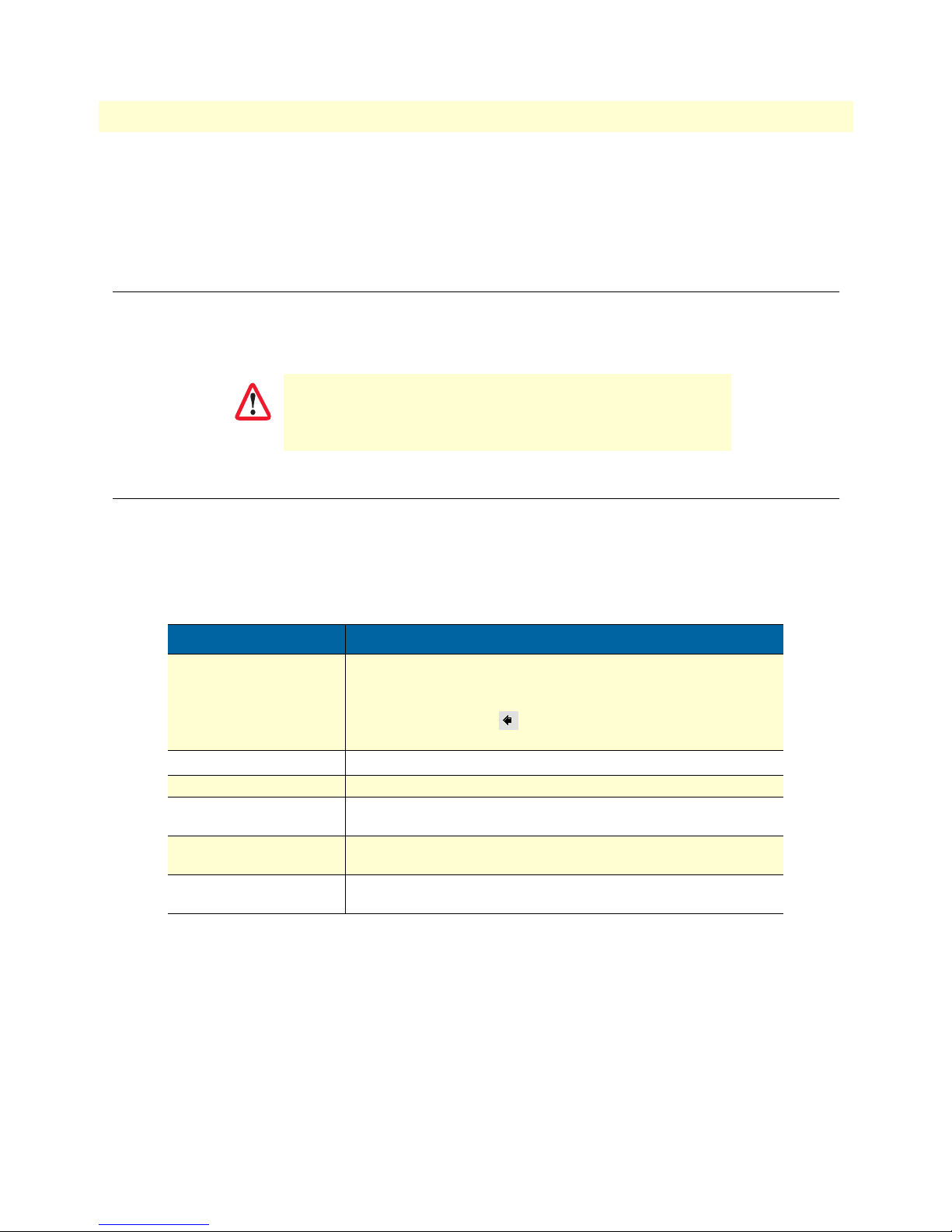
Indicates a cross-reference hyperlink that points to a figure, graphic,
table, or section heading. Clicking on the hyperlink jumps you to the reference. When you finish reviewing the reference, click on the Go to
Previous View button in the Adobe
return to your starting point.
Indicates the names of items.
<CTRL>, <C>, and so on.
system would display them.
Bold Courier font indicates where the operator must type a response
or command
®
Acrobat
®
Reader toolbar to
4
Page 15

5
Model 6511RC Matrix Switch Administrators’ Reference Guide
Mouse conventions
Table 2 lists conventions this guide uses to describe mouse actions.
Table 2. Mouse conventions
Convention Meaning
Left mouse button
Right mouse button This button refers the secondary or rightmost mouse button (unless you
Point This word means to move the mouse in such a way that the tip of the
Click Means to quickly press and release the left or right mouse button (as
Drag This word means to point the arrow and then hold down the left or right
This button refers to the primary or leftmost mouse button (unless you
have changed the default configuration).
have changed the default configuration)
pointing arrow on the screen ends up resting at the desired location.
instructed in the procedure). Make sure you do not move the mouse
pointer while clicking a mouse button. Double-click means to press and
release the same mouse button two times quickly
mouse button (as instructed in the procedure) as you move the mouse to
a new location. When you have moved the mouse pointer to the
desired location, you can release the mouse button.
About this guide
Page 16

About this guide
Model 6511RC Matrix Switch Administrators’ Reference Guide
6
Page 17

Chapter 1
Chapter contents
Introduction............................................................................................................................................................8
Logging into the HTTP/HTML Web Management windows.................................................................................8
HTTP/HTML and SNMP Object Format .............................................................................................................9
Saving HTTP/HTML Object Changes ...................................................................................................................9
Introduction
7
Page 18
8
1 • Introduction
Model 6511RC Matrix Switch Administrators’ Reference Guide
Introduction
You may manage the Model 6511RC Matrix Switch by using its internal HTTP/HTML Web Management
windows. However, to access the HTTP/HTML windows, you must first define:
• The 6511RC system’s LAN IP method to obtain address
• LAN IP address
• LAN IP subnet mask for the 6511RC
If you have not defined the above parameters, refer to the procedures in the Getting Started Guide that came
with your 6511RC
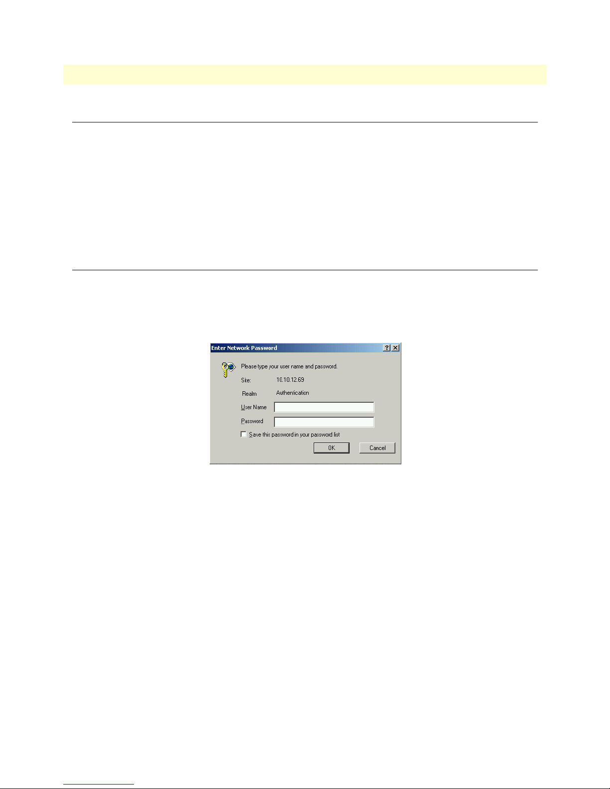
Logging into the HTTP/HTML Web Management windows
To log into the HTTP/HTML Web Management windows, you must enter the 4-octet Internet Protocol (IP)
address (for example, http://your.server.ip.address ) as the Universal Resource Locator (URL) into a World-Wide
Web (WWW) browser. After you enter the IP address, the 6511RC will ask for your user name and password
as shown in figure 1.
Figure 1. 6511RC login window
Your 6511RC will accept the following default administrative username: superuser
Your 6511RC will accept the following default administrative passwords:
• superuser —this password carries full permission to change and view any parameters in the 6511RC
• monitor —this password allows full viewing of any non-password oriented variables.
Note
For security reasons, we recommend that you change these passwords
immediately after initial configuration.
Introduction
Page 19
9
Model 6511RC Matrix Switch Administrators’ Reference Guide
1 • Introduction
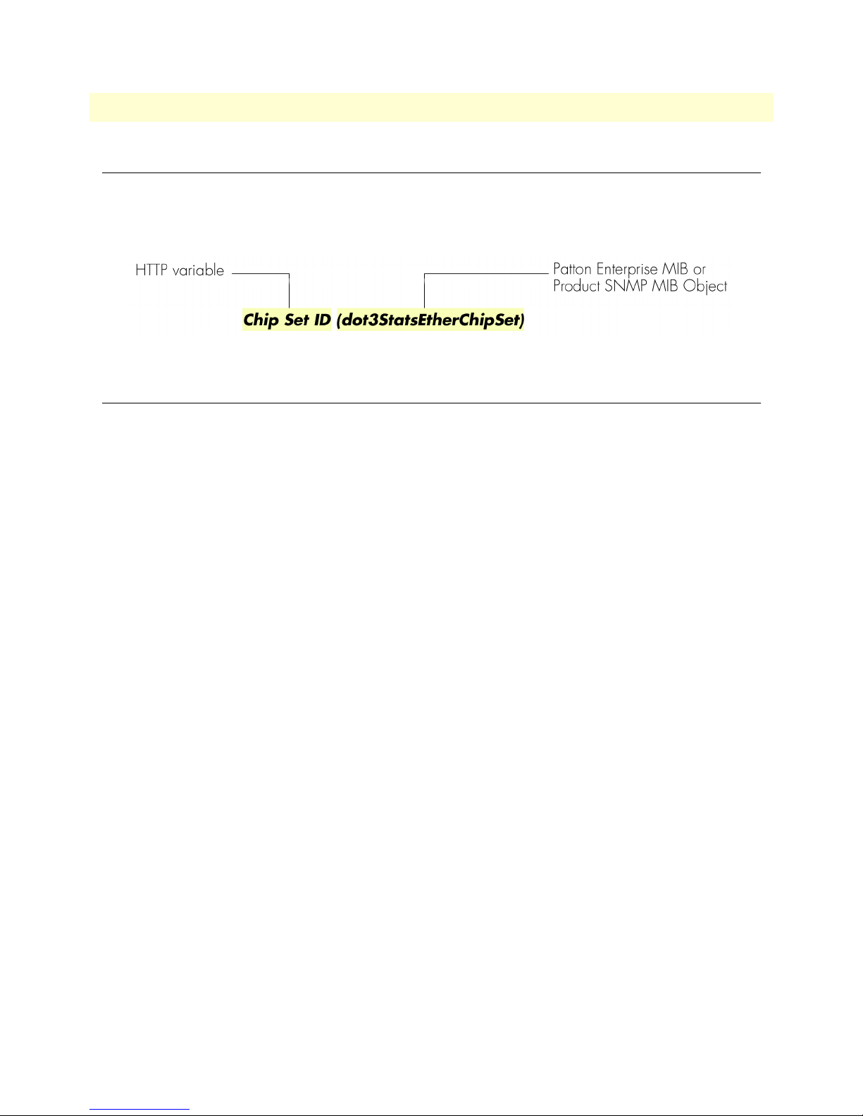
HTTP/HTML and SNMP Object Format
In this document, we shall describe the variables found on each of the internal HTTP/HTML windows. This
description will include brief definitions of the Patton Enterprise MIB or SNMP MIB II object identifiers
wherever applicable. The format of the variables will resemble figure 2.
Figure 2. HTTP/HTML and SNMP object format
Saving HTTP/HTML Object Changes
Sometimes you will need to save changes that you have made in the HTTP/HTML windows. Do the following to make changes to read/write variables:
1. Select the appropriate Modify screen.
2. Make changes to the desired parameter.
3. Click on the Submit button.
4. Return to the HOME screen.
5. Click on the Record Current Configuration button.
Note Make sure you follow steps 1 through 5 when modifying the
HTTP/HTML windows. Otherwise, your changes will be lost when
the 6511RC is power-cycled.
HTTP/HTML and SNMP Object Format
Page 20

1 • Introduction Model 6511RC Matrix Switch Administrators’ Reference Guide
10 Saving HTTP/HTML Object Changes
Page 21

Chapter 2 Home
Chapter contents
Introduction..........................................................................................................................................................12
Product information box .......................................................................................................................................14
Operating status variables ......................................................................................................................................14
Shelf Address (cPCIShelfAddr) .......................................................................................................................14
Slot ID (cPCISlotID) ......................................................................................................................................15
% CPU Idle (boxIdleTime) ............................................................................................................................15
Running Since Last Boot (sysUpTime) ...........................................................................................................15
Current Box State (alarmBoxState) .................................................................................................................15
Total System Alarms (alarmTotal) ..................................................................................................................15
Operator Actions...................................................................................................................................................15
Record Current Configuration (storeConfig(1)) .............................................................................................15
Hard Reset (hardReset(2)) ..............................................................................................................................16
Set Factory Default Configuration (forceDefaultConfig(3)) ............................................................................16
11
Page 22
2 • Home Model 6511RC Matrix Switch Administrators’ Reference Guide
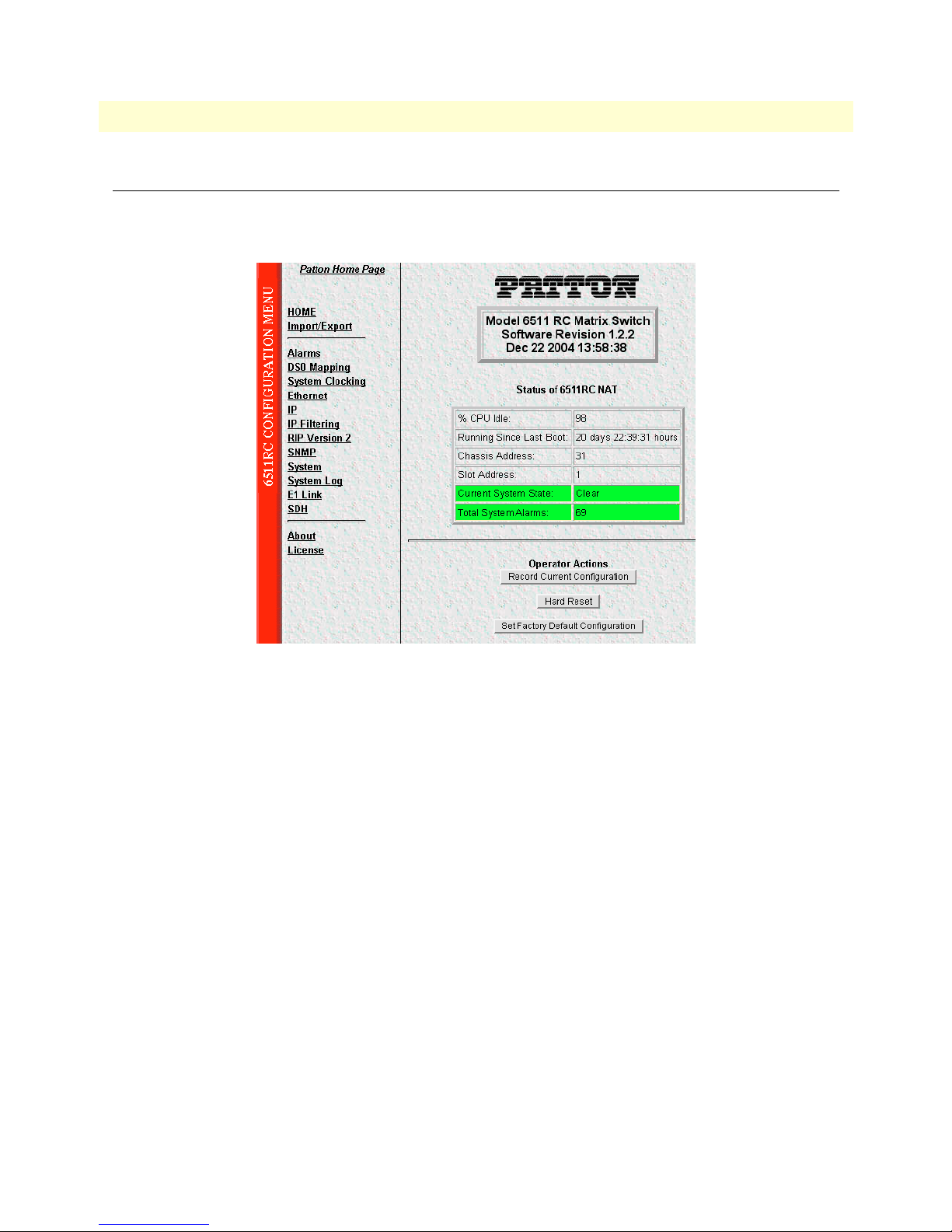
Introduction
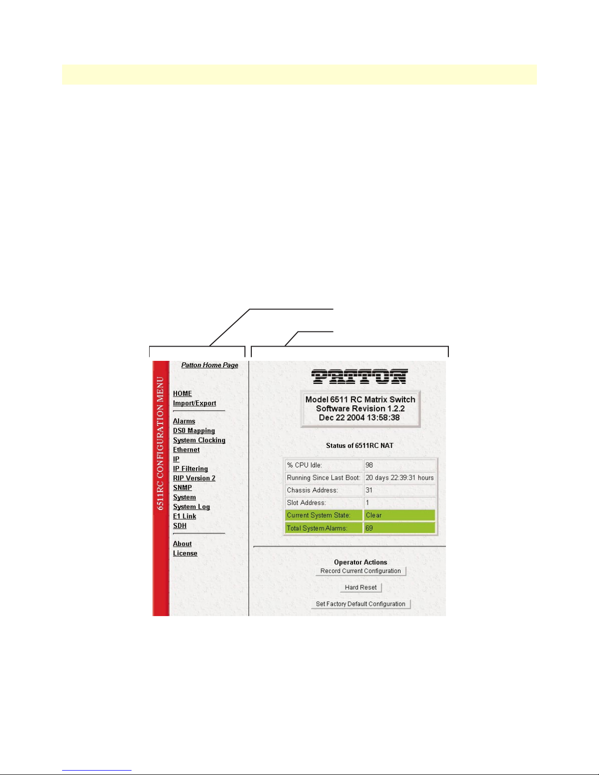
The 6511RC Web Management HOME window is the first management window that you see after logging
into the 6511RC (see figure 3).
Figure 3. HOME window
The HOME window consists of sections that enable you to:
• View general product information about the 6511RC, such as the current software version (see section
“Product information box” on page 14)
• View a summary of the system’s operating status that includes the following information:
– Number of egress ports on the rear blade
– Shelf address
– Slot ID
– Percent of idle CPU time
– Amount of time since the last time the system software was restarted (also referred to as booting)
– Current 6511RC (front blade/rear blade) alarm status, which displays the highest-level alarm currently
detected in the 6511RC—listed as Major, Minor, or Clear (for none)
– Total alarms active in the 6511RC
See section “Operating status variables” on page 14 for more information.
• Initiate the following immediate actions:
– Save any changes you have made to the 6511RC’s system configuration
12 Introduction
Page 23
Model 6511RC Matrix Switch Administrators’ Reference Guide 2 • Home
– Perform a hard reset (cold restart) of the system without power-cycling the 6511RC.
– Set factory default configuation. Reset all the 6511RC’s configurable parameters to their factory-
default values.
See section “Operator Actions” on page 15 for more information.
The HOME window is divided into two panes: the Configuration Menu pane and the configuration/information pane (see figure 4). The Configuration Menu contains the links to the various 6511RC subsystem windows, while the configuration/information pane is where you can view status and other information, or make
changes to the system configuration. Unlike the Configuration Menu pane, which looks the same no matter
which subsystem window you may move to, the configuration/information pane contents will change as you
move from one subsystem window to another.
Note Clicking on the HOME link in the Configuration Menu pane returns you to
the HOME window from any other window.
Configuration Menu pane
Configuration/information pane
Introduction 13
Figure 4. HOME window panes
Page 24
2 • Home Model 6511RC Matrix Switch Administrators’ Reference Guide
5
Patton Electronics Company DSL Cross Connect
Product Name
Software Revision 1.0.14a JUL 10 2003 17:08:4
Software Release Identifier
Figure 5. Product information section of HOME window
Software Release Timestamp
Product information box
The product information box (see figure 5) displays the following:
• Product name: Matrix Switch
• Software release identifier: The current software version running on the 6511RC. The identifier is in the
form X.Y.Z(n) where:
– X denotes a major release involving an extensive system revision.
– Y indicates a revision within Release X adding one or more new features.
– Z denotes a revision within Release X.Y correcting problems that were found in the previous release.
– n (optional) is a lowercase alpha character. The value b for beta may indicate software made available to
certain parties for before the official formal release to the general public, often for early access trials or
field testing.
• Software release timestamp: The date and time the software version was created.
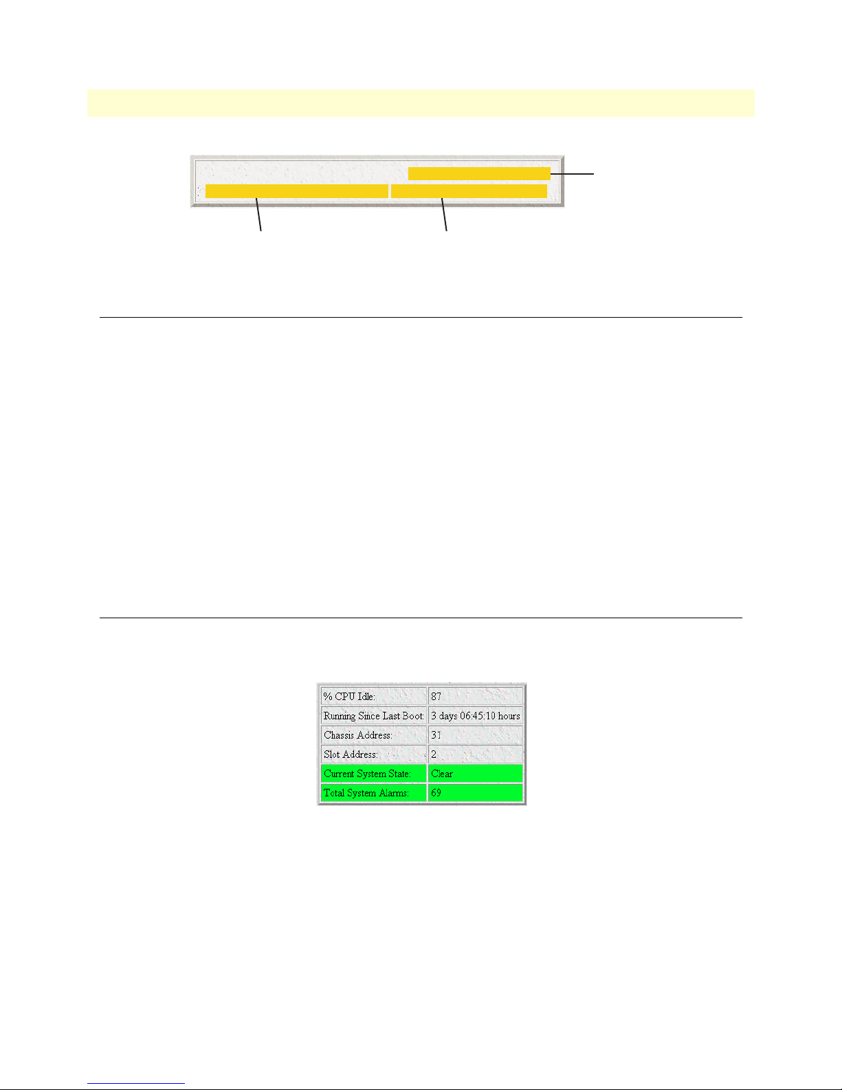
Operating status variables
The system variables that describe the operating status of the 6511RC are shown in figure 6 and described in
the following sections.
Figure 6. Status menu
Shelf Address (cPCIShelfAddr)
Indicates the address of the ForeFront chassis in which the 6511RC resides. The address is set via DIP switches
located on the ForeFront chassis midplane. Using various On/Off combinations up to 33 (0–32) binary shelf
addresses can be defined. See ForeFront chassis User Guide for more information
14 Product information box
Page 25

Model 6511RC Matrix Switch Administrators’ Reference Guide 2 • Home
Slot ID (cPCISlotID)
Indicates the ForeFront chassis slot number occupied by the 6511RC. On the ForeFront chassis models 6276
and 6476, slot numbering sequence starts from the bottom with slot number 1. Numbering sequence for the
ForeFront model 6676 starts from the left of the chassis with slot number 3.
% CPU Idle (boxIdleTime)
Indicates the percent of system CPU capacity currently available to the Model 6511RC.
Running Since Last Boot (sysUpTime)
The time (in hundredths of a second) since the 6511RC was last power-cycled.
Current Box State (alarmBoxState)
The highest level alarm currently active in the 6511RC system—listed as Critical (red), Major (orange), Minor
(yellow), or Clear (green)—no alarms present.
Total System Alarms (alarmTotal)
Total number of alarms currently active in the system.
Operator Actions
In superuser mode you can initiate several operator actions (see figure 7) which will cause the 6511RC to operate according to the descriptions in the following sections.
Figure 7. Operator Actions buttons
Record Current Configuration (storeConfig(1))
Clicking the button labeled Record Current Configuration causes the 6511RC to save the current configuration in permanent Flash memory. In other words, configuration changes made in the subsystem web windows
become permanent when you click Record Current Configuration and the current configuration of the
6511RC will be saved when the 6511RC is powered down.
Configuration changes in the 6511RC are made by clicking a button labeled Submit Query on any of the subsystem window. When you click Submit Query, the 6511RC stores the parameter values in volatile DRAM
(dynamic RAM) only. Since the Submit Query changes take immediate effect, the administrator can test different configuration parameters without needing to change the Flash configuration each time.
Note The most important step after completing the configuration is to save it in
permanent memory by clicking on Record Current Configuration.
Operator Actions 15
Page 26

2 • Home Model 6511RC Matrix Switch Administrators’ Reference Guide
Hard Reset (hardReset(2))
The Hard Reset button causes the 6511RC to perform a cold restart. When you click Hard Reset, the
6511RC requests confirmation before executing the command, after which, the 6511RC will disconnect all
current sessions, re-initialize the interfaces, and re-load configuration parameters from Flash memory.
Set Factory Default Configuration (forceDefaultConfig(3))
The Set Factory Default Configuration button deletes the current configuration from Flash memory and loads
the factory default parameters into Flash. The factory default settings will not take effect in the 6511RC until it has
been re-booted, for example by doing a Hard Reset.
Note Set Factory Default Configuration will delete the 6511RC’s Ethernet IP
address, reset the password to the default administrative passwords (see section “Logging into the HTTP/HTML Web Management windows” on
page 8), and any other site specific-settings made for your particular installation. In order to use the HTTP/HTML Management windows you will
have to re-enter the 6511RC’s Ethernet IP address and netmask using the
6511RC’s front panel control port. Refer to the Getting Started guide for
information on configuring the IP address.
16 Operator Actions
Page 27

Chapter 3 Import/Export
Chapter contents
Introduction..........................................................................................................................................................18
Export current Flash configuration ........................................................................................................................18
Import Flash Configuration From File ..................................................................................................................20
17
Page 28
3 • Import/Export Model 6511RC Matrix Switch Administrators’ Reference Guide
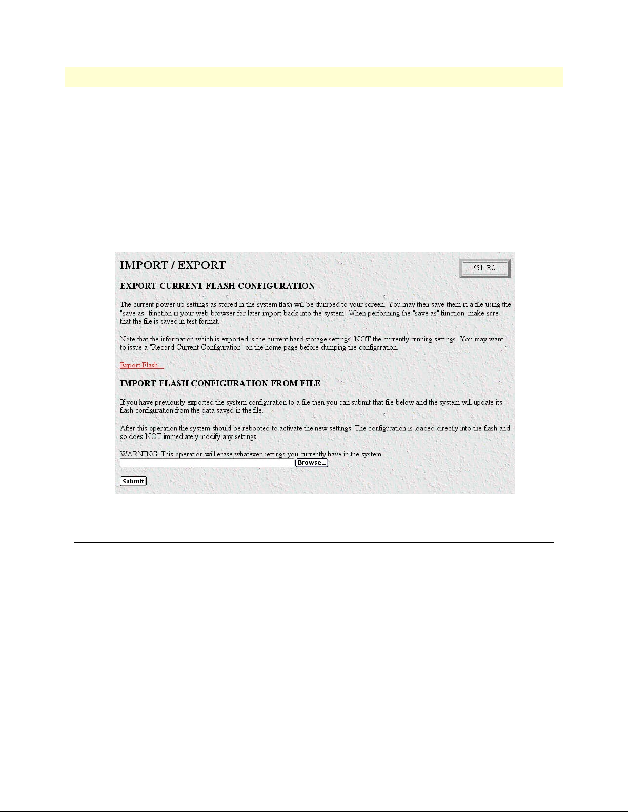
Introduction
The import/export function enables you to make a backup (or exported) copy of your 6511RC’s configuration
parameters. By exporting the configurations, the saved files can quickly be loaded, or imported, into a replacement 6511RC—greatly speeding up the installation process should a 6511RC need replacing.
Note All actions for import/export require superuser access privileges.
To import or export a configuration, click on Import/Export under the Configuration Menu to display the
IMPORT/EXPORT main window (see figure 8).
Figure 8. IMPORT/EXPORT main window
Export current Flash configuration
Note The exported configuration file is a text-format file. Do not try, however to
edit the operating characteristics contained in the file.
Note The parameters that will be exported are the power-up settings as they are
stored in Flash memory and may not be the current operating parameters. To
ensure that you export the most current parameters, go to HOME, then click
on the Record Current Configuration button under Operator Actions.
18 Introduction
Page 29
Model 6511RC Matrix Switch Administrators’ Reference Guide 3 • Import/Export
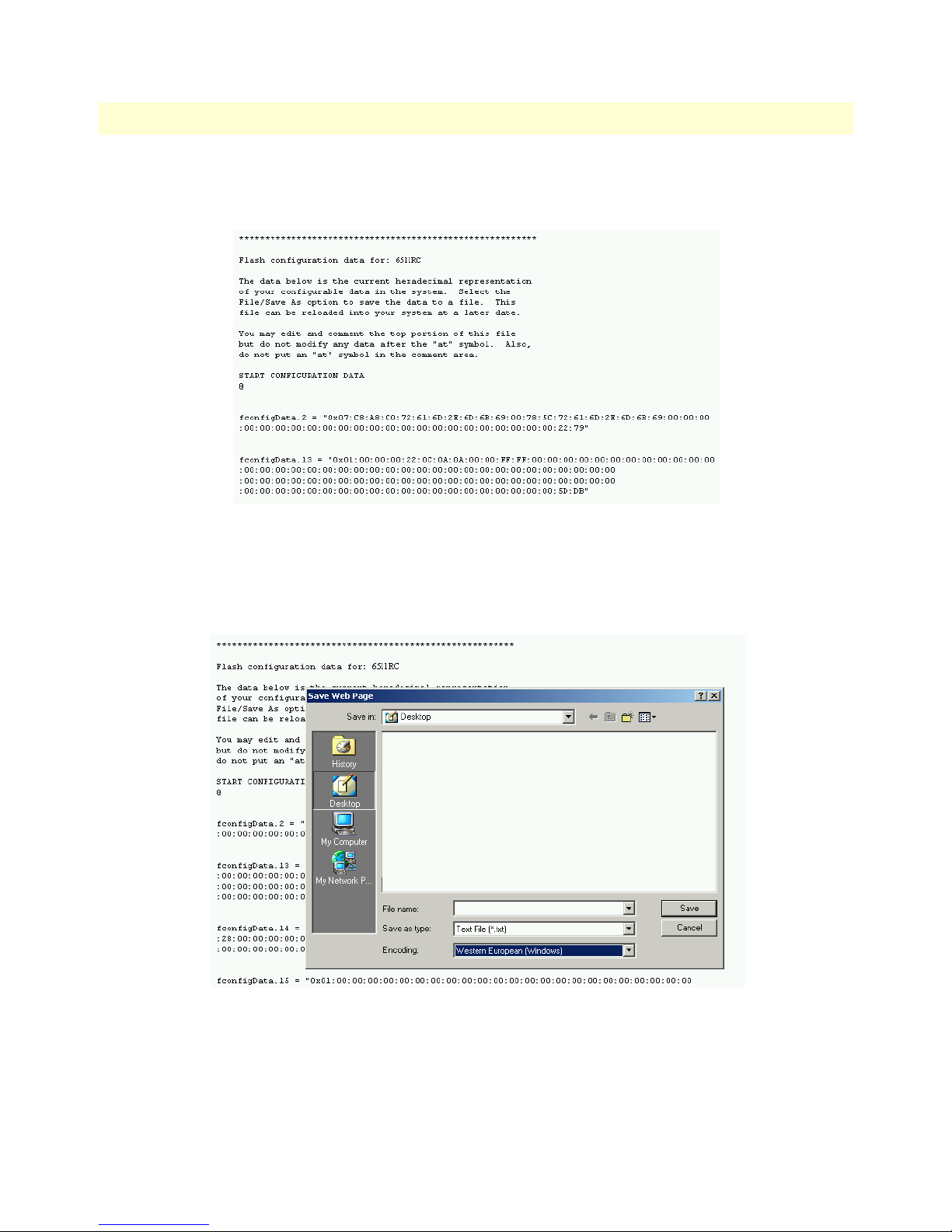
To export the Flash configuration, click on the Export Flash link on the IMPORT/EXPORT main window. The
6511RC will display text configuration information resembling that shown in figure 9.
Figure 9. Typical 6511RC flash memory configuration data
To save the displayed data as a text file, select the Save option on your browser (see figure 10). For example,
under Netscape, select File > Save As. A dialog box will display enabling you to save the contents of the export
parameters to a text file. Select the location where you want the file stored, type a file name, and click Save.
Figure 10. Saving the 6511RC flash memory configuration data as a text file
Export current Flash configuration 19
Page 30

3 • Import/Export Model 6511RC Matrix Switch Administrators’ Reference Guide
Import Flash Configuration From File
To import a configuration file into the 6511RC, type the complete path and filename for the configuration file
you wish to load or click on the Browse…
button (see figure 8 on page 18).
Upon successfully importing the file, the 6511RC will display Configuration Load Complete, indicating that the
new operating parameters have been loaded into Flash memory.
Click on HOME under the Configuration Menu, then click on the Hard Reset button under Operator Actions.
button to select the desired file, then click on the Submit Query
20 Import Flash Configuration From File
Page 31

Chapter 4 Alarms
Chapter contents
Introduction..........................................................................................................................................................22
Alarm System Overview window ...........................................................................................................................22
Alarms management windows ...............................................................................................................................24
Alarm System Configurations window ............................................................................................................25
Alarm Syslog Priority (syslogAlarmPriority) ..............................................................................................25
Alarm Trap IP 1 through 4 (alarmTrapIp0–alarmTrapIp3) ......................................................................26
Temperature Threshold (boxAlarmTemperature) ......................................................................................26
Alarm Severity Configuration .........................................................................................................................26
21
Page 32

4 • Alarms Model 6511RC Matrix Switch Administrators’ Reference Guide
Introduction
The 6511RC provides alarm facilities that monitor the operating status of the 6511RC’s SDH port, path,
H.110 WAN ports, clock synchronization and fallback, and ambient temperature. The 6511RC provides three
alarm signaling methods to indicate that an alarm condition has been detected:
• Visual indication via the 6511RC front panel ALARM and rear blade ALARM status LED indicators
• Operator console indication via the 6511RC management windows
• External alarms management host indication delivered via SNMP traps or Syslog messages that the
6511RC can send to an external alarms management host
By default, all 6511RC alarms are set to display as major (orange-colored) severity events, but you can use the
alarm systems management windows to customize them, assigning a higher or lower level of severity to each item
as desired. Your choices are critical (red), major (orange), minor (yellow), informational (blue), or ignore (no color).
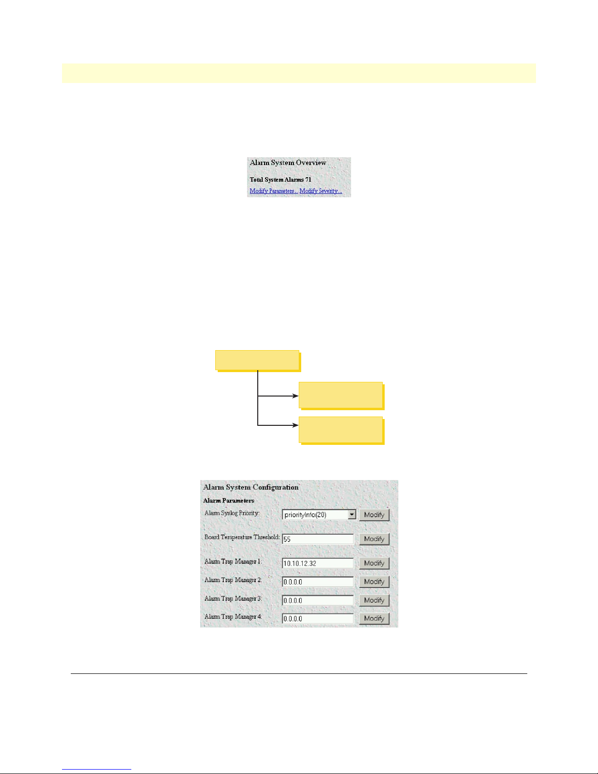
Alarm System Overview window
The Alarm System Overview window (see figure 11) and related windows enable you to manage the 6511RC’s
alarm system. Click on the Alarms hyperlink in the 6511RC’s Configuration Menu to display the Alarm System
Overview window.
Note From the Alarm System Overview window, the system administrator can
force the 6511RC to generate alarms for testing purposes as well as clear
selected alarms.
22 Introduction
Figure 11. Alarm System Overview window
Page 33

Model 6511RC Matrix Switch Administrators’ Reference Guide 4 • Alarms
The 6511RC uses three methods to indicate an alarm condition:
• Front panel LED and rear blade indications—The front panel ALARM LED and rear blade ALARM LED
uses the following three states to indicate the presence and severity of an alarm:
- Off—No alarm is active
- Solid—Minor alarm
- Flashing—Major alarm
Note The 6511RC’s factory-default configuration is to consider all alarms to be
major (orange) ones, so unless you customize the alarms severity levels (see section “Alarm Severity Configuration” on page 26), any alarm that occurs will
cause the ALARM LED to flash, indicating a major alarm—the LED will
never indicate a minor alarm.
Note If both power supplies are functioning normally, the
a solid light, but if one or more power supplies fail, the
POWER
POWER
LED will display
LED will
flash.
Figure 12. Sample alarm indications
• Management web page indication—The Alarms section (see figure 12) of the Alarm System Overview win-
dow (see figure 11 on page 22) uses color-coded highlighting to indicate which alarms are active and the
severity levels of active alarms.
- Red: indicates that one or more critical (severity 4) alarms are active. When active, critical alarm notifica-
tions also appear as red highlighting on the Home window (see figure 6 on page 14) and as a flashing red
star (see figure 49 on page 98) on the System Status window (see figure 48 on page 98).
- Orange: indicates that one or more major (severity 5) alarms are active. When active, major alarm notifications
also appear as orange highlighting on the Home window (see figure 6 on page 14) and as an orange exclamation
mark (see figure 49 on page 98) on the System Status window (see figure 48 on page 98).
- Yellow: indicates that one or more minor (severity 6) alarms are active. When active, minor alarm notifi-
cations also appear as yellow highlighting on the Home window (see figure 6 on page 14) and as a yellow
triangle (see figure 49 on page 98) on the System Status window (see figure 48 on page 98).
Alarm System Overview window 23
Page 34
4 • Alarms Model 6511RC Matrix Switch Administrators’ Reference Guide
- Blue: indicates that one or more informational (severity 7) alarms are active. Being informational in
nature, these alarms only appear on the Alarm System main window to indicate that an event has
occurred, they do not generate alarm indications anywhere else.
Figure 13. Modify Parameters and Modify Severity hyperlinks
• External host indication—For external notification, the 6511RC can be configured to send a Syslog event
notification or an SNMP trap message (or both) to an external alarms management host. To configure the
6511RC to send SNMP traps or Syslog messages in response to alarm conditions, click on the Modify
Parameters hyperlink (see figure 13) to open the Alarm System Configurations—Alarm Response Outputs win-
dow (refer to section “Alarm System Configurations window” on page 25).
In addition to viewing current alarm status, you can force the 6511RC to generate an alarm as a test by clicking
on the Generate Alarm button (see figure 12 on page 23) for the desired alarm. Click on the Clear Alarm button (see figure 12 on page 23) to clear the alarm when the test is concluded.
Alarm System Overview
Modify Alarm
System Parameters
Modify Alarm
Severity
Figure 14. Alarms management diagram
Figure 15. Alarm System Configurations window
Alarms management windows
As shown in figure 11 on page 22 and figure 14, the Alarms System Overview window provides links to the following alarm system management windows:
24 Alarms management windows
Page 35

Model 6511RC Matrix Switch Administrators’ Reference Guide 4 • Alarms
• Modify Parameters—links to the Alarm System Configurations window (see figure 15) for configuring the
alarm response system with the IP addresses of one or more administrators who should be notified in case of
an alarm (refer to section “Alarm System Configurations window”)
• Modify Severity—links to the Alarm Severity Configuration window (see figure 16 on page 26) where you can
configure the severity (importance) of each alarm. For each alarm, you can defined the value of Alarm Severity as critical, major, minor, informational, or ignore. Defining an alarm’s severity as ignore disables that alarm.
(refer to section “Alarm Severity Configuration” on page 26)
Alarm System Configurations window
When an alarm condition occurs, by default the 6511RC does the following to notify administrators of the alarm:
• Activates the front and rear panel Alarm LEDs
• Activates the alarm indications on the 6511RC web management windows (as color-coded highlighting on
the Home window and as a color-coded symbol on the System Status window).
If it has been configured to do so, the 6511RC can also send Syslog and SNMP trap messages to an external alarm
management host. This section describes how to configure the Syslog and/or SNMP trap alarm response outputs.
Click on Modify Parameters (see figure 11 on page 22) to open the Alarm System Configurations window (see
figure 15). Choose the alarm response output that you wish to configure. After defining the value for a desired
alarm response output parameter, click the Submit Query button to the right of the parameter you just modified.
Note You must click Submit Query for each parameter you modify in order to save
your changes. Each submit query button on this page only affects the single
parameter on the same line. Clicking a Submit Query button will not save
changes made to parameter values on other lines.
The following sections describe the Alarm Response Output parameters.
Alarm Syslog Priority (syslogAlarmPriority)
Syslog is a protocol that enables the 6511RC to send event notification messages across IP networks to event message collectors (also known as Syslog Servers or Syslog Daemons). The Alarm Syslog Priority parameter defines what
priority level an event must be at before the 6511RC sends a message to the Syslog daemon. The levels are:
• priorityDisable(1000)
• prioritySystem(80)
• priorityService(60)
• priorityOddity(40)
• priorityInfo(20)
• priorityDebug(10)
• priorityVerbose(5)
Note Unless instructed to do otherwise by Patton Technical Support, you should
leave the Alarm Syslog priority set for prioritySystem(80) (which will only
generate a Syslog message for incidents greater than the System priority level)
or priorityDisable(1000) (which deactivates Syslog message sending).
Alarms management windows 25
Page 36

4 • Alarms Model 6511RC Matrix Switch Administrators’ Reference Guide
For more information on Syslog messages, refer to chapter 13, “System Log” on page 111.
Alarm Trap IP 1 through 4 (alarmTrapIp0–alarmTrapIp3)
Simple Network Management Protocol (SNMP) trap daemons are a tool for managing TCP/IP networks, they are
a simple method of alerting a management host of a problem with a device or application. The Alarm Trap IP
parameter is the IP address of a host running the SNMP trap daemon that will be receiving messages sent from the
6511RC. Upon the occurrence of an alarm, the 6511RC sends an SNMP trap message to the host system (or a
management station) defined by this parameter.
Note The Alarm Trap IP requires that an IP address be entered. If you do not want
the 6511RC to send SNMP trap messages, entering an address of 0.0.0.0
disables SNMP trap message sending.
Temperature Threshold (boxAlarmTemperature)
An alarm message is generated when the internal box temperature exceeds this value in degrees Celsius. You can
change the threshold temperature, but we recommend using the factory default of 55° C.
Alarm Severity Configuration
This section describes configuring alarm severity levels. Clicking on Modify Severity (see figure 11 on page 22)
displays the Alarm Severity Configuration window (see figure 16) listing of 6511RC alarms. From this window
you can assign the severity for each alarm (critical, major, minor, informational, or ignore).
Figure 16. Alarm Severity Configuration window
The alarms can be independently configured to generate alarm messages. Each alarm item can be set for one of
the following severity levels:
• critical(4)—When active, critical alarm notifications appear as red highlighting on the Home window (see
figure 6 on page 14) and as a flashing red star (see figure 49 on page 98) on the System Status window (see
figure 48 on page 98).
• major(5)—When active, major alarm notifications appear as orange highlighting on the Home window (see
figure 6 on page 14) and as an orange exclamation mark (see figure 49 on page 98) on the System Status window
(see figure 48 on page 98).
26 Alarms management windows
Page 37

Model 6511RC Matrix Switch Administrators’ Reference Guide 4 • Alarms
• minor(6)—When active, minor alarm notifications appear as yellow highlighting on the Home window (see
figure 6 on page 14) and as a yellow triangle (see figure 49 on page 98) on the System Status window (see
figure 48 on page 98).
• informational(7)—Being informational in nature, these alarms only appear as blue highlighting on the
Alarm System main window to indicate that an event has occurred, they do not generate alarm indications
anywhere else.
• ignore(0)—The 6511RC will not generate an alarm.
Note You can disable an alarm (as appropriate for your application) by defining its
severity as ignore.
Note The 6511RC’s factory-default configuration is to consider all alarms to be
major (orange) ones, unless you customize the alarm’s severity levels.
To configure the severity for a selected alarm, click on the drop-down menu for the that alarm, select the
desired severity value, then click on Submit Query to implement the change.
Alarms management windows 27
Page 38

4 • Alarms Model 6511RC Matrix Switch Administrators’ Reference Guide
28 Alarms management windows
Page 39

Chapter 5 DS0 Mapping
Chapter contents
Introduction..........................................................................................................................................................30
DS0 Mapping Overview main window..................................................................................................................30
DACS Display Type parameter .............................................................................................................................31
Mapping Help.......................................................................................................................................................32
Defining a DS0 map using the Long Form............................................................................................................32
TuFormat static connections ...........................................................................................................................33
TUG-3 (Tributary Unit Group 3) (tug3) ..................................................................................................33
TUG-2 (Tributary Unit 2) (tug2) .............................................................................................................33
TU-12 (Tributary Unit 12) (tu12) ............................................................................................................34
E1 Slots .....................................................................................................................................................34
H.110 Direction .......................................................................................................................................34
H.110 Port Number .................................................................................................................................34
H.110 Slot ................................................................................................................................................34
E1 port format static connections ....................................................................................................................35
Port Type ..................................................................................................................................................35
E1 Number ...............................................................................................................................................35
Slots ..........................................................................................................................................................35
H.110 Port Number .................................................................................................................................35
H.110 Slot ................................................................................................................................................35
Defining DS0 mappings using the command line interface (CLI) .........................................................................36
Saving a DS0 mapping definition..........................................................................................................................37
Defined Mappings table (static connections) .........................................................................................................38
ID (daxConnectionID) ...................................................................................................................................38
Tug-3 ..............................................................................................................................................................38
Tug-2 ..............................................................................................................................................................38
Tu-12 .............................................................................................................................................................38
E1 # ................................................................................................................................................................38
E1 Slots ...........................................................................................................................................................38
H.110 Type ....................................................................................................................................................38
H.110 Number ...............................................................................................................................................38
H.110 Timeslots .............................................................................................................................................39
DS0 Connection ID (DAX Connection ID) window............................................................................................39
Viewing the DS0 Connection ID window ......................................................................................................39
Deleting a DS0 Mapping ................................................................................................................................39
29
Page 40

5 • DS0 Mapping Model 6511RC Matrix Switch Administrators’ Reference Guide
Introduction
The Model 6511RC Matrix Switch concentrates the traffic capacity of up to 63 E1 lines for delivery over a
155.52 Mbps optical or electrical STM-1interface. The Matrix Switch provides an interface to the TDM midplane bus within the ForeFront chassis. The total capacity of the TDM midplane bus is 4096 simplex DS0s,
the equivalent of 64 E1s. Each DS0 channel can be mapped in either direction, transmitting to the TDM midplane bus or receiving from the TDM midplane bus. The 6511RC places the DS0 traffic into the STM-1 multiplexer for transport over the SDH network. To place DS0 traffic from the TDM midplane bus to the STM-1
you must define a DS0 mapping (also called an internal connection or cross-connection). The source is DS0 traffic
on the H.110 side, and the destination are STM-1 virtual containers. The 6511RC’s DS0 Mapping Overview
window (see figure 17) provides the means for managing (mapping) internal connections.
Devices connect to the 6511RC via the STM-1 optical or electrical interface, and H.110 ports. (A device will
connect to an H.110 port via the 6511RC’s interface to the TDM midplane bus in the cPCI chassis midplane). Each DS0 mapping defines a one-to-one connection between a selected number of timeslots on one
H.110 port and an E1 port or a TU-12. Use the DS0 Mapping management web page to define these DS0
mappings (internal connections) and to view previously defined mappings.
DS0 Mapping Overview main window
The DS0 Mapping Configuration window and related windows provide the means for you to manage the
6511RC DS0 mapping subsystem. To display the DS0 Mapping Configuration window (see figure 17), on the
6511RC Configuration Menu, click the DS0 Mapping link.
30 Introduction
Figure 17. DS0 Mapping Overview window
Page 41

Model 6511RC Matrix Switch Administrators’ Reference Guide 5 • DS0 Mapping
DS0 Mapping
Mapping
Help
DS0
Connection
Figure 18. DS0 Mapping diagram
The DS0 mapping window contains the following:
• DACS Display Type menu you can use to select the Long Form or the Command Line Form methods for con-
figuring the cross-connection mapping (see section “DACS Display Type parameter”)
• Mapping Help button that displays the online help window (see section “Mapping Help” on page 32)
• E1 input format menu used to select Tug format (tuFormat) or the E1 Format (E1PortFormat)
• Configure Static Connections section in Tu or E1 format where you can create the cross-connections (see sec-
tion “Defining a DS0 map using the Long Form” on page 32 or section “Defining DS0 mappings using the
command line interface (CLI)” on page 36)
• Static Connection section where you can view the previously defined DS0 mappings (cross-connections) in
the 6511RC (see section “Defined Mappings table (static connections)” on page 38)
DACS Display Type parameter
To define DS0 mappings (connections), you can use either the Long Form or the Command Line Form. To
choose the method you prefer, use the DACS Display Type drop-down box to select one of the following param-
eter values:
• displayLongForm(0)—(Factory Default). Most people consider Long Form the easier method for defining
DS0 mappings.The Long Form displays the DS0 Mapping page in the standard management window format with drop-down boxes and text box fields. Use this format to define the DS0 Mapping parameters by
selecting values from drop-down boxes and typing values in the text box fields. (Refer to section “Defining
a DS0 map using the Long Form” on page 32 for information on using the Long Form to configure static
connections.)
• displayCliForm(1)—Advanced users of the command line interface (CLI) method may consider CLI a faster
and more convenient method than the Long Form. To use CLI to define DS0 mappings, select
displayCliForm(1) and click on the Submit Query button. The DS0 Mapping page will refresh, displaying
a single text box (in place of the drop-down boxes and text box parameter fields) into which you may enter
CLI commands. (Refer to section “Defining DS0 mappings using the command line interface (CLI)” on
page 36 for information on using the CLI to configure static connections.)
DACS Display Type parameter 31
Page 42

5 • DS0 Mapping Model 6511RC Matrix Switch Administrators’ Reference Guide
Mapping Help
Clicking on the Mapping Help button displays the DS0 Mapping Help window (see figure 18). The DS0 Mapping Help page provides a convenient online tutorial on how to use the 6511RC’s web management pages to
define DS0 mappings (cross-connections). The tutorial includes definitions for all configurable parameters on
the DS0 Mapping web page. If you are using command line format to define DS0 connections, scroll down to
the Command Line Format heading.
Figure 19. DACS Help Information window
Defining a DS0 map using the Long Form
DS0 connections can be entered using one of two E1 input formats:
• TU (Tributary Unit) format—DS0s from the TDM midplane bus are mapped into E1 timeslots which in
turn are placed into TU-12 containers with a max capacity for 32 E1 DS0s each (see figure 20).
• E1 port format—DS0s from the H.110 are placed into E1 timeslots corresponding to one of 63 E1 ports.
STM-1
STM-0
x1
AUG-1
x1
x1
AU-4
x3
AU-3 VC-3
Pointer processing
Multiplexing
Aligning
Mapping
VC-4
x3
TUG-3
x7
x7
TUG-2
Figure 20. SDH multiplexing diagram
x3
C-12VC-12TU-12
32 Mapping Help
Page 43

Model 6511RC Matrix Switch Administrators’ Reference Guide 5 • DS0 Mapping
TuFormat static connections
To create a DS0 map (cross-connection) between the DS0s from the H.110 and the STM-1 containers using
the TuFormat follow the instructions below.
Figure 21. Configure Static Connections section of DS0 Mapping Configuration window
The drop-down menus in the Defining a Mapping section of the DS0 Mapping Configuration window (see
figure 21) are organized into tug-3, tug-2, Tu12 and H.110 fields, the Tu designators follow standard SDH/
STM-1 terminology. In displayLongForm mode, you will use drop-down menus and text boxes to define the
DS0 mapping parameters. The following parameters define each channel mapped connection (see figure 21).
• TUG level 3 (tug3)
• TUG Level 2 (tug2)
• TU-12 Level (tu12)
• E1 Slots (Slots)
• H.110 Direction (toH110, fromH110)
• H.110 port number
• H.110 Slots
TUG-3 (Tributary Unit Group 3) (tug3)
There are three TUG-3 multiplexers in a STM-1. Each TUG-3 accepts up to 7 TUG-2 (21 E1 capacity). The
options are:
• tug3-1(1)
• tug3-2(2)
• tug3-3(3)
TUG-2 (Tributary Unit 2) (tug2)
Each TUG-2 container carries up to 3 E1s. Up to 7 TUG-2 are carried in a TUG-3 container. The options are:
• tug2-1(1)
• tug2-2(2)
• tug2-3(3)
• tug2-4(4)
• tug2-5(5)
• tug2-6(6)
Defining a DS0 map using the Long Form 33
Page 44

5 • DS0 Mapping Model 6511RC Matrix Switch Administrators’ Reference Guide
• tug2-7(7)
TU-12 (Tributary Unit 12) (tu12)
Each TU-12 container takes one E1 (32 DS0 Slots). Groups of 3 TU-12s are placed into TUG2 containers.
The options are:
• tu12-1(1)
• tu12-2(2)
• tu12-3(3)
E1 Slots
The field labeled E1 Slots accepts values from 1 to 32, these correspond to DS0s mapped from and two the
H.110 bus.
H.110 Direction
Display indicating the direction of traffic to and from the TDM midplane bus.
H.110 Port Number
The DS0 Mapping page provides two rows of parameter fields for defining H.110 connections. When defining
an H.110 connection, you must define values for all parameters in both rows. The parameters in the first row
define the transmit port (to the TDM midplane bus) and parameters in the second row define the receive port
(from the TDM midplane bus). There are up to 32 configurable H.110 ports.
H.110 Slot
H.110 ports can support up to 128 slots (DS0s).
Note You must define the same number of time slots for each side of the connec-
tion. In other words, the number of time slots defined for the H.110 ports in
either direction must be the same.
To configure the time slots parameter, enter a text string specifying which time slot numbers will be used for
the channel. You must enter a text string that comprises the following elements:
• Numerals—Use numerals (0, 1, 2, 3, 4, 5, 6, 7, 8, 9) to represent time slot numbers
• Comma—Use the comma (,) to separate non-contiguous timeslots. For example, the string 1,7,15 repre-
sents three timeslots numbered 1, 7, and 15.
Slot numbering examples:
For example, to define a channel comprising timeslots 1, 2, 5, 6, 7, and 15, either of the following entries
would be valid:
• 1,2,5,6,7,15
• 1,2,5-7,15
34 Defining a DS0 map using the Long Form
Page 45

Model 6511RC Matrix Switch Administrators’ Reference Guide 5 • DS0 Mapping
Although the first string above is valid syntax, the second string is easier to read, and more clearly shows what is
going on. The following strings are also valid syntax:
• 1-2,5,6,7,15
• 1-2,5,6-7,15
• 1-2,5-6,7,15
E1 port format static connections
The E1 port long format allows an STM-1 multiplexer to be defined in E1 Port terms. Instead of representing
STM-1 multiplexing in terms of TUG-2 or TUG-3, the E1 Port format simply shows all 63 E1 ports carried
by the STM-1 interfaces, enabling direct DS0 mapping from the TDM midplane bus onto any of the 63 E1s.
The drop-down menus for the E1 format screens are organized as follows:
• Port Type
• E1 Number
• E1 Slots
• H.110 Direction (toH110, fromH110)
• H.110 port number
• H.110 Slots
Port Type
This is a fixed E1 port.
E1 Number
Selects the E1 number. Options are from 1 to 63.
Slots
The field labeled Slots accepts values anywhere from 1–32, these correspond to DS0s within any of the 63 E1s.
H.110 Port Number
The DS0 Mapping page provides two rows of parameter fields for defining H.110 connections. When defining
an H.110 connection, you must define values for all parameters in both rows. The parameters in the first row
define the transmit port (to the TDM midplane bus) and parameters in the second row define the receive port
(from the TDM midplane bus). There are up to 32 configurable H.110 ports.
H.110 Slot
Each H.110 port can support up to 128 slots (DS0s).
Note You must define the same number of time slots for each side of the connec-
tion. In other words, the number of time slots defined for the H.110 ports in
either direction must be the same.
Defining a DS0 map using the Long Form 35
Page 46

5 • DS0 Mapping Model 6511RC Matrix Switch Administrators’ Reference Guide
To configure the time slots parameter, enter a text string specifying which time slot numbers will be used for
the channel. You must enter a text string that comprises the following elements:
• Numerals—Use numerals (0, 1, 2, 3, 4, 5, 6, 7, 8, 9) to represent time slot numbers
• Comma—Use the comma (,) to separate non-contiguous timeslots. For example, the string 1,7,15 repre-
sents three timeslots numbered 1, 7 and 15.
Defining DS0 mappings using the command line interface (CLI)
To define a new connection using CLI, you must enter text strings in the following format:
t1-e1:Port#:Slots/toH110:Port#:Slots/fromH110:Port#:Slots
• t1-e1—The fixed format for E1 ports in the STM-1 hierarchy.
• Port# (1–63)—Any of the 63 E1s available.
• Slots (1–32)—E1 timeslots range from 1 through 32.
• to H110:Port#—Indicates the H.110 port number and transmission from 6511RC to TDM midplane bus
Note There are a maximum of 32 ports available for the TDM midplane bus. If
the port number selected is not within the range supported an error will be
generated.
• Slots:—Number of H.110 slots (1–128). The range should have a maximum of 32 slots, this corresponds to
the maximum capacity of 32 slots per E1.
• FromH.110: Port #–Indicates the H.110 port number and transmission from TDM midplane bus to
6511RC.
• Slots—Number of H.110 slots (1–128). The range should have a maximum of 32 slots, this corresponds to
the maximum capacity of 32 slots per E1.
Note You must define the same number of time slots for each side of the connec-
tion.In other words, the number of time slots defined for toH.110 must be the
same as the number of time slots defined for fromH.110.
To configure the time slots parameter, enter a text string specifying which time slot numbers will be used for
the channel. You must enter a text string that comprises the following elements:
• Numerals—Use numerals (0, 1, 2, 3, 4, 5, 6, 7, 8, 9) to represent time slot numbers
• Comma—Use the comma (,) to separate non-contiguous timeslots. For example, the string 1,7,15 repre-
sents three timeslots numbered 1, 7 and 15.
• Dash (-)—Use the dash (-) to represent a series of contiguous timeslots. For example, the string 1-31 repre-
sents all timeslots between 1 and 31 inclusive (that is, time slot 1, time slot 31 and all time slots in between).
36 Defining DS0 mappings using the command line interface (CLI)
Page 47

Model 6511RC Matrix Switch Administrators’ Reference Guide 5 • DS0 Mapping
Slot numbering examples:
For example, to define a channel comprising timeslots 1, 2, 5, 6, 7, and 15, either of the following entries
would be valid:
• 1,2,5,6,7,15
• 1,2,5-7,15
Although the first string above is valid syntax, the second string is easier to read, and more clearly shows what is
going on. The following strings are also valid syntax:
• 1-2,5,6,7,15
• 1-2,5,6-7,15
• 1-2,5-6,7,15
While the entries above would work, they are harder to grasp quickly than the first two examples. Beyond the
cluttered appearance of these last three strings, they tend to obscure the part of reality they represent: the contiguous block of timeslots from 5-7.
CLI example:
To define a DS0 mapping between a E1 line, Port 1, timeslots 1–32, sent to H.110 port 1, timeslots 1–32 and
from H.110 port 2, timeslots 1–32 type the following text:
t1-e1:1:1-32/H.110:1:1-32/H.110:2:1-32
Saving a DS0 mapping definition
Now that you have entered the parameters required to define the DS0 mapping you must save your crossconnection map to the 6511RC’s random access memory (RAM) in order to activate the connection. To save
the DS0 mapping, click the Submit Query button to save the static connection.
Saving a DS0 mapping definition 37
Page 48

5 • DS0 Mapping Model 6511RC Matrix Switch Administrators’ Reference Guide
Defined Mappings table (static connections)
The Define a Mapping (static connections) section of the DS0 Mapping Configuration window (see figure 22)
displays all previously defined DS0 mappings (cross-connections) in the 6511RC. The parameter details are
described in the following paragraphs.
Figure 22. Configure Static Connections section of DS0 Mapping Configuration window
ID (daxConnectionID)
The connection ID is a number (a positive non-zero integer) that uniquely identifies each DS0 mapping. Connection IDs start with the number one (1), and are incremented sequentially. As DS0 mappings (connections)
are defined, the 6511RC assigns connection IDs automatically. When the user enters DS0 mapping parameters
and clicks the Submit Query button, the 6511RC automatically assigns the next available ID number in
sequence to that connection.
Tug-3
Displays the type of STM-1 multiplexed TUG-3 group.
Tug-2
Displays the type of STM-1 multiplexed TUG-2 group.
Tu-12
Displays the type of STM-1 multiplexed TU-12 group.
E1 #
Displays the E1 port number.
E1 Slots
Displays which 64-kbps time slots (also referred to as the DS0 data communications channels) are used for the
corresponding E1 port.
H.110 Type
Displays the direction of timeslots in reference to the TDM midplane bus.
H.110 Number
Displays the H.110 port number.
38 Defined Mappings table (static connections)
Page 49

Model 6511RC Matrix Switch Administrators’ Reference Guide 5 • DS0 Mapping
H.110 Timeslots
Displays the H.110 timeslots.
DS0 Connection ID (DAX Connection ID) window
The DS0 Connection ID window provides the capability to delete an existing DS0 mapping (connection). The
page also displays all the mapping parameters which define the connection.
Viewing the DS0 Connection ID window
To view the DS0 Connection ID window for a certain DS0 mapping (connection):
1. On the DSO Mapping page, under Static Connections, find the Connection ID number for the DS0 map-
ping you wish to view.
2. Click the Connection ID number hyperlink to display the DS0 Connection ID window for the selected
connection ID.
Deleting a DS0 Mapping
To delete the DS0 Mapping displayed on the DS0 Connection ID window:
1. In the drop-down menu for the Connection Status parameter, ensure that the value delete(1) is selected.
2. Click the Submit Query button to delete the connection (DS0 mapping).
DS0 Connection ID (DAX Connection ID) window 39
Page 50

5 • DS0 Mapping Model 6511RC Matrix Switch Administrators’ Reference Guide
40 DS0 Connection ID (DAX Connection ID) window
Page 51

Chapter 6 System Clocking
Chapter contents
Introduction..........................................................................................................................................................42
System Clocking Overview window.......................................................................................................................42
Clocking Parameters section ...........................................................................................................................43
Module Clocking Fallback (sysGSClockMode) .........................................................................................43
Module Clocking Source (daxClockMainRef and daxClockFallbackRef) ..................................................44
Module Clocking Fallback ........................................................................................................................44
Operator Actions buttons ................................................................................................................................44
Clocking Status section ...................................................................................................................................45
Clock Source .............................................................................................................................................45
Fallback Indication ....................................................................................................................................45
Clock Status ..............................................................................................................................................45
Saving your work ............................................................................................................................................46
41
Page 52

6 • System Clocking Model 6511RC Switch Matrix Administrators’ Reference Guide
Introduction
During operation, the T-DAC synchronizes data transmission on all DS0 channels with a clock pulse, called the
reference clock. This reference clock synchronizes all the cards in the ForeFront chassis, or all the cards in a chassis
segment in the Model 6676 ForeFront chassis. The configuration of the system clocking parameters select the
source for that clock pulse. (The T-DAC generates the synchronizing clock from this source). In the following discussion, the clock sources are called Main Reference and Fallback Reference on the web management pages.
The clocking subsystem includes a fallback auto-recovery mechanism by which the T-DAC monitors a Main
clock Reference (source) and switches to a Fallback Reference (source) if the main reference becomes unavailable. Once the main reference clock is re-established, the auto-recover feature switches the clocking back to the
main reference. By default, the clocking fallback mechanism is disabled at the factory prior to the T-DAC’s
shipment. To activate the T-DAC’s fallback system, you must enable it.
The following parameters control the T-DAC’s clocking subsystem: Module Clocking Mode, Module Clocking
Source, and Module Clocking Fallback.
Figure 23. System Clocking Overview window
System Clocking Overview window
The System Clocking Overview window enables you to define the system clocking parameters and view certain
clocking status information. To display the System Clocking Overview window (see figure 23), click the System
Clocking link on the Configuration Menu pane.
42 Introduction
Page 53

Model 6511RC Switch Matrix Administrators’ Reference Guide 6 • System Clocking
The System Clocking Overview window includes the following items:
• Clocking Parameters section—Displays the configurable system clocking parameters and non-configurable
(display-only) parameters (see section “Clocking Parameters section” on page 43).
• Operator Actions buttons section—Provides buttons for clearing the system fallback state, forcing the
6511RC into fallback clocking state, clearing error conditions, and displaying the clocking help window
(see section “Operator Actions buttons” on page 44).
• Clocking Status Information table—Displays a set of display-only parameters intended for use by software
engineers during field debugging. Therefore, most 6511RC end-users will not use this information. (See
section “” on page 45.)
Clocking Parameters section
The following sections describe the system clocking parameters.
Note When you are finished configuring the system clocking parameters, make
sure you save the changes (see section “Saving your work” on page 46).
Module Clocking Fallback (sysGSClockMode)
The Fallback Feature Desired State and the Auto Recovery Feature Desired State parameters define the 6511RC’s
clocking fallback and fallback auto recovery mechanism as enabled or disabled.
The fallback feature, when enabled, allows the 6511RC to switch to a secondary clock as follows:
• Master or secondary mode—The 6511RC, upon failure of the primary reference clock source, will switch
to the selected fallback reference clock source.
• Slave Mode—The 6511RC defaults (fallback feature options are not accessible to user) to system for both
main reference and fallback reference—since the slave cards do not provide clock to the chassis, they receive
clock from the system clocking bus provided by a master or secondary card.
By default, the clocking fallback mechanism is disabled at the factory before the 6511RC is shipped. To activate the 6511RC’s fallback system you must enable it. When disabled, the 6511RC will not use the fallback
reference clocking source, even if the primary reference becomes unavailable. To define the enable or disable
the fallback system parameter, select one of the following values from the drop-down menu.
• disable(0)
• enable(1)
Once you have defined the desired value for the Enable/Disable Fallback System parameter, you must click the
Modify button below the auto recovery feature menu to save your selection into volatile DRAM.
The Auto Recovery Feature Desired State, when enabled, will cause a 6511RC (in master or secondary mode),
which is operating on fallback reference clock due to a failure of the primary reference clock, to switch back to
primary reference clock when it becomes available.
By default, Auto Recovery Feature Desired State is disabled at the factory before the 6511RC is shipped. To acti-
vate the 6511RC’s clock auto recovery system you must enable it. When disabled, the 6511RC, operating on
fallback reference clock, will not switch back to primary reference clock, even if the primary reference becomes
available. To define the enable or disable the fallback system parameter, select one of the following values from
the drop-down menu.
System Clocking Overview window 43
Page 54

6 • System Clocking Model 6511RC Switch Matrix Administrators’ Reference Guide
• disable(0)
• enable(1)
Once you have defined the desired value for the Enable/Disable Auto Recovery System parameter, you must click
the Modify button below the auto recovery feature menu to save your selection into volatile DRAM.
Module Clocking Source (daxClockMainRef and daxClockFallbackRef)
The Primary Reference and Fallback Reference parameters define a primary and secondary (fallback) reference for
the 6511RC system clock source (and for all blades in the chassis when the 6511RC’s clocking mode is defined as
master). The 6511RC will use the fallback reference if and only if the primary reference becomes unavailable. By
default, the clocking fallback mechanism is disabled at the factory before the 6511RC is shipped. To activate the
6511RC’s fallback system you must enable it (see section “Module Clocking Fallback”).
When defining the main and fallback clocking sources, you can select the STM-1 WAN port, the 6511RC
internal clock pulse oscillator, or a system clock provided by another blade in the same chassis. The 6511RC
will use the main reference as its system clocking source unless the main reference fails or is disconnected.
When the primary reference becomes unavailable 6511RC will switch to the fallback reference as its system
clocking source.
Both parameters will be defined from the same set of possible values. For the fallback reference to serve its purpose, however, you must define it by selecting a value different from the main reference. You must also enable
the 6511RC’s fallback mechanism (see Enable/Disable Fallback System). For the 6511RC’s primary and secondary clocking references, you can choose:
• WAN(602)—Clocking derived from the SDH network clock received at the STM-1 interface.
• internal(200)—Uses the 6511RC internal free-running oscillator for the clock source.
• system(500)—Uses the system clock reference provided by another blade in the chassis for the clock source.
Automatically selected when the card is operating in slave mode.
Module Clocking Fallback
This parameter defines the 6511RC’s clocking fallback mechanism as enabled or disabled. By default, the
clocking fallback mechanism is disabled at the factory before the 6511RC is shipped. To activate the 6511RC’s
fallback system you must enable it. When disabled, the 6511RC will not use the fallback reference clocking
source, even if the primary reference becomes unavailable. To define the enable or disable the fallback system
parameter, select one of the following values from the drop-down menu.
• disable(0)
• enable(1)
Once you have defined the desired value for the Enable/Disable Fallback System parameter, you must click the
adjacent Modify button to save your selection into volatile DRAM.
Operator Actions buttons
The immediate actions buttons with their respective functions are described below:
• Clear Fallback—Clicking the Clear Fallback button clears the system clocking fallback state by setting the
value of fallback state to primary(0). The 6511RC will stop using the fallback reference and return to using
the defined primary reference as its clocking source
44 System Clocking Overview window
Page 55

Model 6511RC Switch Matrix Administrators’ Reference Guide 6 • System Clocking
• Force Fallback—Clicking the Force Fallback button forces the 6511RC into the fallback clocking state by
setting the value of FallBack State to fallback(1). The 6511RC will switch to the defined fallback reference
as its clocking source.
• Clear Errors—Clicking the Clear Errors button clears the 6511RC’s error condition for all clock signals.
For all clock signals, the 6511RC will reset the dynamic error variables to a value of noError(0).
• Help—Clicking the Help button displays the DACS Clocking Help window (see figure 24).
Figure 24. System Clocking help window
Clocking Status section
The Clocking Status displays status information for Clock Source, Fallback Indication, and Clock Status.
Clock Source
Indicates the clock source in use, possible values are:
• unknown(0)
• mainRef(1)
• fallbackRef(2),
• masterClk(3),
• secondaryClk(4),
• internal(5)
Fallback Indication
Displays status of fallback system:
• Inactive—The 6511RC clock is derived from the main reference clock.
• Active—The 6511RC has switched its clocking source to the fallback reference clock.
Clock Status
Displays the presence of clock alarms since last time unit was rebooted or last time alarms were cleared.
• No Alarm
• Alarms
System Clocking Overview window 45
Page 56

6 • System Clocking Model 6511RC Switch Matrix Administrators’ Reference Guide
Saving your work
Once you have defined your desired values for the system clocking parameters, you must click the Submit
Query button to save your settings into volatile DRAM.
46 System Clocking Overview window
Page 57

Chapter 7 Ethernet
Chapter contents
Introduction..........................................................................................................................................................48
Ethernet main window ..........................................................................................................................................48
State (boxEtherAState) ....................................................................................................................................48
PrimaryIPAddress (boxEtherAPrimaryIpAddress) ...........................................................................................49
PrimaryIpMask (boxEtherAPrimaryIpMask) ...................................................................................................49
PrimaryIpFilters (boxEtherAPrimaryIpFilters) ................................................................................................49
SecondaryIpAddress (boxEtherASecondaryIpAddress) ....................................................................................49
SecondaryIpMask (boxEtherASecondaryIpMask) ............................................................................................49
SecondaryIpFilters (boxEtherASecondaryIpFilters) .........................................................................................49
Technique (boxEtherATechnique) ..................................................................................................................49
Ethernet Configuration window............................................................................................................................50
State (boxEtherAState) ....................................................................................................................................50
PrimaryIPAddress (boxEtherAPrimaryIpAddress) ...........................................................................................50
PrimaryIpMask (boxEtherAPrimaryIpMask) ...................................................................................................50
PrimaryIpFilters (boxEtherAPrimaryIpFilters) ................................................................................................50
SecondaryIpAddress (boxEtherASecondaryIpAddress) ....................................................................................51
SecondaryIpMask (boxEtherASecondaryIpMask) ............................................................................................51
SecondaryIpFilters (boxEtherASecondaryIpFilters) .........................................................................................51
Technique (boxEtherATechnique) ..................................................................................................................51
Ethernet Statistics window.....................................................................................................................................51
Alignment Errors (dot3StatsAlignmentErrors) ................................................................................................51
FCS Errors (dot3StatsFCSErrors) ...................................................................................................................51
Single Collision Frames (dot3StatsSingleCollision Frames) .............................................................................52
Multiple Collision Frames (dot3StatsMultipleCollisionFrames) ......................................................................52
SQE Test Errors (dot3StatsSQETestErrors) ....................................................................................................52
Deferred Transmissions (dot3StatsDeferredTransmissions) .............................................................................52
Late Collisions (dot3StatsLateCollisions) ........................................................................................................52
Excessive Collisions (dot3StatsExcessiveCollisions) .........................................................................................52
Other Errors (dot3StatsInternalMacTransmitErrors) ......................................................................................52
Carrier Sense Errors (dot3StatsCarrierSenseErrors) .........................................................................................52
Received Frames Too Long (dot3StatsFrameTooLongs) .................................................................................52
Other Received Errors (dot3StatsInternalMacReceiveErrors) ..........................................................................52
Chip Set ID (dot3StatsEtherChipSet) .............................................................................................................52
47
Page 58

7 • Ethernet Model 6511RC Matrix Switch Administrators’ Reference Guide
Introduction
The access server provides management and statistical information in the Ethernet Overview window (see
figure 25). Detailed information regarding the SNMP MIB II variables may be downloaded from RFC 1643,
Definitions of Managed Objects for the Ethernet-like Interface Types.
Click on Ethernet under the Configuration Menu to display the Ethernet Overview main window.
The Ethernet Overview main window displays information about the configuration of the Ethernet interface
including IP addresses, subnet masks, and state of the Ethernet link.
The Ethernet interface contains the following links:
• Ethernet Statistics link—Clicking on the Statistics link takes you to the page where you can see the statistics
on the ethernet interface. For more information about the Statistics page, refer to “Ethernet Statistics win-
dow” on page 51.
• Modify Parameters… link—Clicking on the Modify link takes you to the page where you can change the
configuration of your ethernet interface. For more information about modifying Ethernet settings, refer to
“Ethernet Configuration window” on page 50.
Figure 25. Ethernet Overview main window
Ethernet main window
The Ethernet main window shows the current configuration of the Ethernet interface. The following sections
describe each parameter.
State (boxEtherAState)
Indicates the state of the ethernet interface. The following states are valid:
• notInstalled(0)—Ethernet interface is not physically present
• noLinkIndication(1)—no cable is connected to the Ethernet interface. Hub is not seen.
• adminOff(2)—Ethernet interface has been turned off by setting technique to disable
• linkIndication10M(3)—Ethernet is 10M
• linkIndication10Duplex(4)—Ethernet is 10M full duplex
48 Introduction
Page 59

Model 6511RC Matrix Switch Administrators’ Reference Guide 7 • Ethernet
• linkIndication100M(5)—Ethernet is 100M
• linkIndication100Duplex(6)—Ethernet is 100M full duplex
PrimaryIPAddress (boxEtherAPrimaryIpAddress)
The primary Ethernet IP address.
PrimaryIpMask (boxEtherAPrimaryIpMask)
The primary Ethernet IP subnet mask.
PrimaryIpFilters (boxEtherAPrimaryIpFilters)
Filters packets based on the filters assigned to the Primary IP address of the Ethernet port. Enter the filter ID of
a filter configured under Filter IP. Use a comma (,) to separate multiple filters.
SecondaryIpAddress (boxEtherASecondaryIpAddress)
The secondary Ethernet IP address.
Note This address is not propagated via RIP.
SecondaryIpMask (boxEtherASecondaryIpMask)
The secondary IP Ethernet IP subnet mask.
SecondaryIpFilters (boxEtherASecondaryIpFilters)
Filters packets based on the filters assigned to the secondary IP address of the Ethernet port. Enter the filter ID
of a filter configured under Filter IP. Use a comma (,) to separate multiple filters.
Note Only outbound filters can be applied to the secondary Ethernet. Inbound fil-
ters for the secondary Ethernet must be entered in the Primary IP Filter field.
Technique (boxEtherATechnique)
Turns ethernet port off and on. The remote access server must be reset for this setting to take effect.
• disable(0)—Ethernet port is disabled
• static(1)—Ethernet port is turned on. IP address(es) and mask(s) are obtained from data entered under the
Ethernet link.
Ethernet main window 49
Page 60

7 • Ethernet Model 6511RC Matrix Switch Administrators’ Reference Guide
Ethernet Configuration window
The Ethernet Configuration window (see figure 26) allows you to make changes to the Ethernet configuration.
To reach this window, select Modify Parameters… from the Ethernet Overview main window.
Figure 26. Ethernet Configuration window
State (boxEtherAState)
Indicates the state of the Ethernet interface. The following states are valid:
• notInstalled(0)—Ethernet interface is not physically present
• noLinkIndication(1)—no cable is connected to Ethernet interface. Hub is not seen.
• adminOff(2)—Ethernet interface has been turned off by setting technique to disable
• linkIndication10M(3)—Ethernet is 10M
• linkIndication10Duplex(4)—Ethernet is 10M full duplex
• linkIndication100M(5)—Ethernet is 100M
• linkIndication100Duplex(6)—Ethernet is 100M full duplex
PrimaryIPAddress (boxEtherAPrimaryIpAddress)
The primary Ethernet IP address.
PrimaryIpMask (boxEtherAPrimaryIpMask)
The primary Ethernet IP subnet mask.
PrimaryIpFilters (boxEtherAPrimaryIpFilters)
Filters packets based on the filters assigned to the Primary IP address of the Ethernet port. Enter the Filter ID
of a filter configured under Filter IP. Use a comma (,) to separate multiple filters.
50 Ethernet Configuration window
Page 61

Model 6511RC Matrix Switch Administrators’ Reference Guide 7 • Ethernet
SecondaryIpAddress (boxEtherASecondaryIpAddress)
The secondary Ethernet IP address.
Note This address is not propagated via RIP.
SecondaryIpMask (boxEtherASecondaryIpMask)
The secondary IP Ethernet IP subnet mask.
SecondaryIpFilters (boxEtherASecondaryIpFilters)
Filters packets based on the filters assigned to the Secondary IP address of the Ethernet port. Enter the Filter
ID of a filter configured under Filter IP. Use a comma (,) to separate multiple filters.
Technique (boxEtherATechnique)
Turns Ethernet port off and on. The remote access server must be reset for this setting to take effect.
• disable(0)—Ethernet port is disabled
• static(1)—Ethernet port is turned on. IP address(es) and mask(s) are obtained from data entered under the
Ethernet link.
Ethernet Statistics window
The Ethernet Statistics window (see figure 27) shows statistics about the Ethernet interface. To reach this win-
dow select Ethernet Statistics… from the Ethernet Overview main window.
Alignment Errors (dot3StatsAlignmentErrors)
The number of frames received that are not an integral number of octets in length and do not pass the FCS check.
Figure 27. Ethernet Statistics window
FCS Errors (dot3StatsFCSErrors)
The number of frames received that are an integral number of octets in length but do not pass the FCS check.
Ethernet Statistics window 51
Page 62

7 • Ethernet Model 6511RC Matrix Switch Administrators’ Reference Guide
Single Collision Frames (dot3StatsSingleCollision Frames)
The number of successfully transmitted frames in which there was exactly one collision.
Multiple Collision Frames (dot3StatsMultipleCollisionFrames)
The number of successfully transmitted frames in which there was more than one collision.
SQE Test Errors (dot3StatsSQETestErrors)
The number of times that the SQE TEST ERROR message is generated by the PLS sublayer.
Deferred Transmissions (dot3StatsDeferredTransmissions)
The number of times in which the first transmission attempt is delayed because the medium is busy. This number does not include frames involved in collisions.
Late Collisions (dot3StatsLateCollisions)
The number of times that a collision is detected later than 512 bit-times into the transmission of a packet. Five
hundred and twelve bit-times corresponds to 51.2 microseconds on a 10 Mbps system.
Excessive Collisions (dot3StatsExcessiveCollisions)
The number of frames in which transmission failed due to excessive collisions.
Other Errors (dot3StatsInternalMacTransmitErrors)
The number of frames transmission on a fails due to an internal MAC sublayer transmit error.
Carrier Sense Errors (dot3StatsCarrierSenseErrors)
The number of times that the carrier sense condition was lost or never asserted when attempting to transmit a
frame on a particular interface.
Received Frames Too Long (dot3StatsFrameTooLongs)
The number of frames received that exceed the maximum permitted frame size.
Other Received Errors (dot3StatsInternalMacReceiveErrors)
The number of frames in which reception fails due to an internal MAC sublayer receive error.
Chip Set ID (dot3StatsEtherChipSet)
Ethernet-like interfaces are typically built out of several different chips. This value identifies the chip set that
gathers the transmit and receive statistics and error indications.
52 Ethernet Statistics window
Page 63

Chapter 8 IP
Chapter contents
Introduction..........................................................................................................................................................55
IP main window ....................................................................................................................................................56
Hyperlinks ......................................................................................................................................................57
IP parameters and statistics....................................................................................................................................57
Forwarding .....................................................................................................................................................57
Default Time-To-Live ....................................................................................................................................57
Total Datagrams Received ..............................................................................................................................58
Discarded for Header Errors ...........................................................................................................................58
Discarded for Address Errors ...........................................................................................................................58
Forwarded Datagrams .....................................................................................................................................58
Discarded for Unknown Protos .......................................................................................................................58
Discarded with No Errors ...............................................................................................................................58
Total Deliveries ...............................................................................................................................................58
Out Requests ..................................................................................................................................................58
Out Discards ...................................................................................................................................................58
Discarded for No Routes ................................................................................................................................59
Reassembly Timeout .......................................................................................................................................59
# of Reassembled Fragments ...........................................................................................................................59
# Successfully Reassembled .............................................................................................................................59
Reassembly Failures ........................................................................................................................................59
# Fragmented OK ...........................................................................................................................................59
# Fragmented Failed .......................................................................................................................................59
# Fragments Created .......................................................................................................................................59
# Valid but Discarded .....................................................................................................................................59
Modify IP Configuration window .........................................................................................................................59
Forwarding (ipForwarding) .............................................................................................................................60
Default Time-To-Live (ipDefaultTTL) ...........................................................................................................60
Saving Your Work ..........................................................................................................................................60
IP Addressing Information window.......................................................................................................................61
Address window ..............................................................................................................................................61
Entry Interface Index (ipAdEntIfIndex) ....................................................................................................61
Entry Subnet Mask (ipAdEntNetMask) ....................................................................................................61
Entry Broadcast Address (ipAdEntBcastAddr) ...........................................................................................61
Entry Reassembly Maximum Size (ipAdEntReasmMaxSize) .....................................................................61
IP Routing Information window ...........................................................................................................................62
Destination (genRouteDest) ...........................................................................................................................62
Mask (genRouteMask) ....................................................................................................................................62
Gateway (genRouteGateway) ..........................................................................................................................63
Cost (genRouteCost) ......................................................................................................................................63
53
Page 64

8 • IP 6511RC Matrix Switch Administrators’ Reference Guide
Interface (genRouteIfIndex) ............................................................................................................................63
Protocol (genRouteProto) ...............................................................................................................................63
State (RouteState) ...........................................................................................................................................63
Add a route: ....................................................................................................................................................64
Destination (ipRouteDest) ........................................................................................................................64
Mask (ipRouteMask) .................................................................................................................................64
Gateway (genRouteGateway) ....................................................................................................................64
Advanced… ....................................................................................................................................................64
Destination (ipRouteDest) ........................................................................................................................64
Mask (ipRouteMask) .................................................................................................................................64
Gateway (genRouteGateway) ....................................................................................................................64
Route Destination window....................................................................................................................................64
Route Destination (genRouteDest) .................................................................................................................65
Mask (genRouteMask) ....................................................................................................................................65
Interface (genRouteIfIndex) ............................................................................................................................65
Protocol (genRouteProto) ...............................................................................................................................65
Seconds Since Updated (genRouteAge) ...........................................................................................................65
Tag (genRouteTag) .........................................................................................................................................66
Gateway (genRouteGateway) ..........................................................................................................................66
Cost (genRouteCost) ......................................................................................................................................66
State (genRouteState) ......................................................................................................................................66
Forwarding Table ..................................................................................................................................................66
Destination (ipRouteDest) ..............................................................................................................................66
Mask (ipRouteMask) ......................................................................................................................................66
Next Hop (ipRouteNextHop) .........................................................................................................................67
Interface (ipRouteIfIndex) ..............................................................................................................................67
Type (ipRouteType) .......................................................................................................................................67
Protocol (ipRouteProto) ..................................................................................................................................67
Info (ipRouteInfo) ..........................................................................................................................................67
Address Translation Information window..............................................................................................................68
Interface (ipNetToMediaIfIndex) ...................................................................................................................68
Net Address (ipNetToMediaNetAddress) .......................................................................................................68
Physical (ipNetToMediaPhysAddress) ............................................................................................................68
Type (ipNetToMediaType) ............................................................................................................................68
54
Page 65

6511RC Matrix Switch Administrators’ Reference Guide 8 • IP
Introduction
The 6511RC’s IP subsystem manages addressing and routing parameters and statistics pertaining to IP protocol operation on the 6511RC. Managing the IP subsystem involves monitoring IP statistics and parameters,
and defining IP addressing and routing parameters.
Note All items described in this chapter are defined in RFC 1213: Management
Information Base for Network Management of TCP/IP-based internets: MIB-II.
Click on the IP link in the 6511RC’s configuration menu pane, to display the IP Overview main window (see
figure 28).
Introduction 55
Figure 28. IP Overview main window
Page 66

8 • IP 6511RC Matrix Switch Administrators’ Reference Guide
IP main window
The IP Overview main window provides hyperlinks to the windows shown in figure 29.
IP
Overview
IP
Configuration
IP Addressing
Overview
IP Address
Details
IP Routing
Overview
IP Route
Destination
IP Forwarding
Table
IP Address
Translation
TCP
TCP
Details
UDP
Datagrams
ICMP
Figure 29.
IP Overview
main window and related windows
The IP Overview main window displays certain IP statistics as well as the status of the IP forwarding mechanism (forwarding or not forwarding). The following sections describe the contents of the IP main window.
56 IP main window
Page 67

6511RC Matrix Switch Administrators’ Reference Guide 8 • IP
Hyperlinks
The IP window provides the following hyperlinks to the windows shown in figure 29. You can use these subpages to view and modify the values of certain IP parameters:
• TCP—Clicking the TCP hyperlink displays the TCP window (see section “TCP Overview main window”
on page 114).
• Modify—Clicking the Modify hyperlink displays the IP Forwarding sub-window where you can modify
the values of the IP forwarding and time-to-live parameters (see “Modify IP Configuration window” on
page 59).
• Addressing Info—Clicking the Addressing hyperlink displays the IP Addressing Overview sub-window.
This window (see “IP Addressing Information window” on page 61) displays each IP address and its associ-
ated 6511RC interface ID number, and a Details…. for each IP address. The Details hyperlink displays the
IP address Details sub-window for that IP address.
• Routing Info—Clicking the Routing Info hyperlink displays IP Routing Overview sub-window. This win-
dow displays the defined IP Routes table that the 6511RC uses to routing IP datagrams. For each route, the
table shows the IP address, subnet mask, next hop router, and interface) You can use this window to add IP
routes to the 6511RC’s routing table by defining IP routing parameters (see “IP Routing Information win-
dow” on page 62).
• Address Translation Info—Clicking the Address Translation hyperlink displays the IP address translation
sub-window where you can view and define the 6511RCs physical to logical (MAC to IP) address correlations (mappings) (see “Address Translation Information window” on page 68).
IP parameters and statistics
The following sections describe the IP parameters and statistics displayed on the IP Overview main window.
Forwarding
The Forwarding parameter defines whether the 6511RC acts as an IP gateway in respect to the forwarding of
datagrams received by, but not addressed to the 6511RC. IP gateways forward datagrams. IP hosts do not forward datagrams, except in the case when the host is the source of the datagram.
Note For some managed nodes, this object may take on only a subset of the values
possible. Accordingly, it is appropriate for an agent to return a “badValue”
response if a management station attempts to change this object to an inappropriate value.
One of the following values may be defined for ipForwarding:
• forwarding(1)—acting as a gateway and will forward IP datagrams to other gateways
• not-forwarding(2)—not acting as a gateway so it will discard IP datagrams destined for other gateways
Default Time-To-Live
The default value inserted into the time-to-live field of the IP header of datagrams originated at the 6511RC,
whenever a TTL value is not supplied by the transport layer protocol.
IP parameters and statistics 57
Page 68

8 • IP 6511RC Matrix Switch Administrators’ Reference Guide
Total Datagrams Received
The total number of input datagrams received from interfaces, including those received in error.
Discarded for Header Errors
The number of input datagrams discarded due to errors in their IP headers, including bad checksums, version
number mismatch, other format errors, time-to-live exceeded, errors discovered in processing their IP options,
and so on.
Discarded for Address Errors
The number of input datagrams discarded because the IP address in their IP header’s destination field was not
a valid address to be received at the 6511RC. This count includes invalid addresses (e.g., 0.0.0.0) and addresses
of unsupported Classes (e.g., Class E). For entities which are not IP Gateways and therefore do not forward
datagrams, this counter includes datagrams discarded because the destination address was not a local address.
Forwarded Datagrams
The number of input datagrams for which the 6511RC was not their final IP destination, as a result of which
an attempt was made to find a route to forward them to that final destination. In entities which do not act as
IP Gateways, this counter will include only those packets which were source-routed via the 6511RC, and the
source-route option processing was successful.
Discarded for Unknown Protos
The number of locally-addressed datagrams received successfully but discarded because of an unknown or
unsupported protocol.
Discarded with No Errors
The number of input IP datagrams for which no problems were encountered to prevent their continued processing, but which were discarded (for example, due to lack of buffer space).
Note The Discarded w/No Errors counter does not include any datagrams dis-
carded while awaiting re-assembly.
Total Deliveries
The total number of input datagrams successfully delivered to IP user-protocols (including ICMP).
Out Requests
The total number of IP datagrams which local IP user-protocols (including ICMP) supplied to IP in requests
for transmission.
Note The Out Requests counter does not include any datagrams counted in
ipForwDatagrams.
Out Discards
The number of output IP datagrams for which no problem was encountered to prevent their transmission to
their destination, but which were discarded (e.g., for lack of buffer space).
58 IP parameters and statistics
Page 69

6511RC Matrix Switch Administrators’ Reference Guide 8 • IP
Note The Out Discards counter would include datagrams counted in ipForwDat-
agrams if any such packets met this (discretionary) discard criterion.
Discarded for No Routes
The number of IP datagrams discarded because no route could be found to transmit them to their destination.
Note The Discarded for No Routes counter includes any packets counted in
ipForwDatagrams which meet this “no-route” criterion. This includes any
datagrams which a host cannot route because all of its default gateways are
down.
Reassembly Timeout
The maximum number of seconds which received fragments are held while they are awaiting reassembly at the
6511RC.
# of Reassembled Fragments
The number of IP fragments received which needed to be reassembled at the 6511RC.
# Successfully Reassembled
The number of IP datagrams successfully reassembled.
Reassembly Failures
The number of failures detected by the IP reassembly algorithm (for whatever reason: timed out, errors, etc.).
Note The Reassembly Failures value is not necessarily a count of discarded IP frag-
ments since some algorithms (notably the algorithm in RFC 815) can lose
track of the number of fragments by combining them as they are received.
# Fragmented OK
The number of IP datagrams that have been successfully fragmented at the 6511RC.
# Fragmented Failed
The number of IP datagrams that have been discarded because they required fragmenting at the 6511RC, but
were not fragmented because their Don’t Fragment option was set.
# Fragments Created
The number of IP datagram fragments that have been generated at the 6511RC.
# Valid but Discarded
The number of routing entries which were chosen to be discarded even though they are valid. One possible
reason for discarding such an entry could be to make more buffer space available for other routing entries.
Modify IP Configuration window
The IP Configuration window (see figure 30) provides the means for you to view and modify the values of the
IP Forwarding and Default Time-to-Live parameters for the 6511RC.
Modify IP Configuration window 59
Page 70

8 • IP 6511RC Matrix Switch Administrators’ Reference Guide
Figure 30. IP Configuration window
To display the IP Configuration window, on the IP management web page, click the Modify… link.
Forwarding (ipForwarding)
Determines whether the 6511RC is acting as an IP gateway that will forward datagrams received by-but not
addressed to-the 6511RC. IP gateways forward datagrams, IP hosts do not (except those source-routed via the
host).
Note For some managed nodes, this object may take on only a subset of the values
possible. Accordingly, it is appropriate for an agent to return a “badValue”
response if a management station attempts to change this object to an inappropriate value.
The following options are available:
• forwarding(1)—acting as a gateway
• not-forwarding(2)—not acting as a gateway
Default Time-To-Live (ipDefaultTTL)
The default value inserted into the Time-To-Live (TTL) field in the IP header of datagrams originating from
the 6511RC, whenever a TTL value is not already supplied by the transport layer protocol.
Saving Your Work
Once you have defined your desired values for the configurable parameters shown in the IP Configuration subpage, you must click the Submit Query button to save the new values into volatile DRAM. Once you click the
button, the 6511RC will implement the changes immediately.
Note To save your changes permanently, you must visit the 6511RC HOME page,
and click the Save Current Configuration button. When you click the Save
Current Configuration button, the 6511RC will copy the configuration currently stored in volatile DRAM into non-volatile Flash memory for persistent storage.
60 Modify IP Configuration window
Page 71
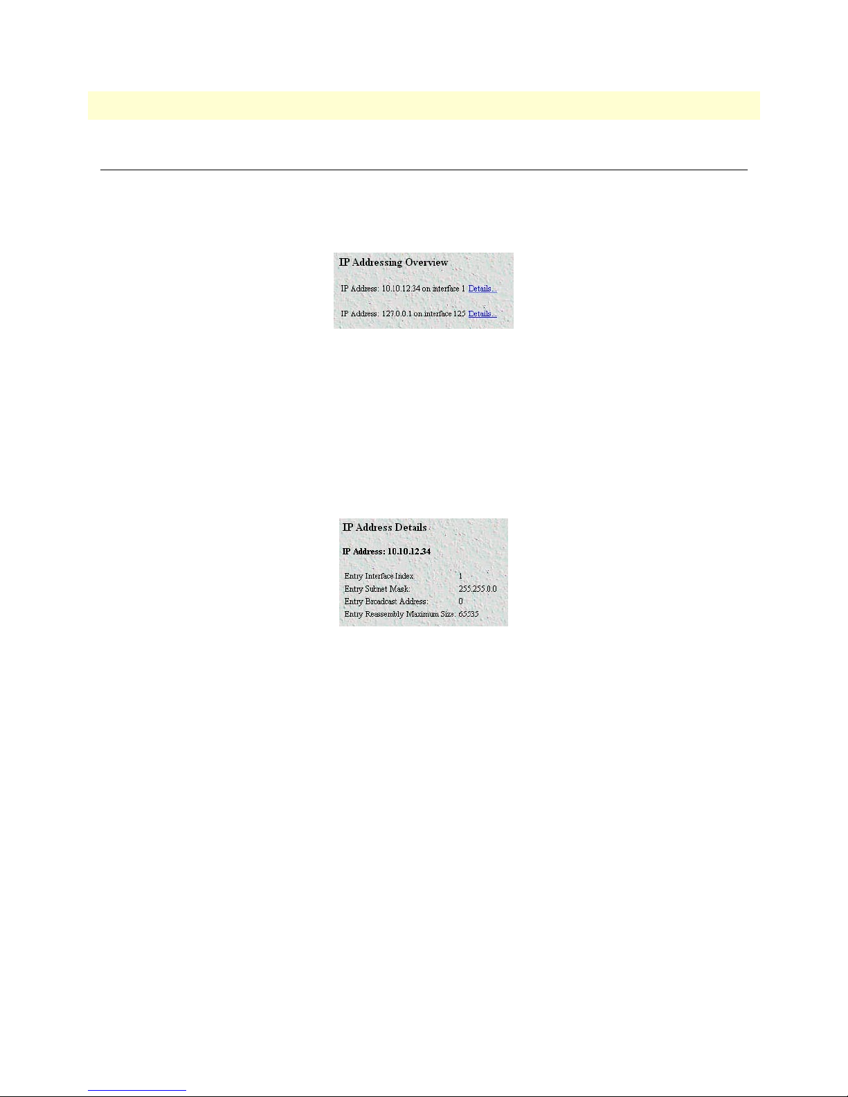
6511RC Matrix Switch Administrators’ Reference Guide 8 • IP
IP Addressing Information window
The IP addressing Information window (ipAdEntAddr) window (see figure 31) provides the means for you to
view the default address for outgoing IP datagrams, the IP addresses defined for the 6511RC and the interface
ID associated with each address.
Figure 31. IP addressing Information window
For each IP address on the page, there is a Details hyperlink. Clicking the Details hyperlink displays the
Address window.
Address window
The Address window (see figure 32) displays the contents of the 6511RC’s IP address table for each network
interface defined on the blade. To display the Address window, on the IP ADDRESSING INFORMATION
page, select the interface you wish to view, and click the Details hyperlink.
Figure 32. Address window
Entry Interface Index (ipAdEntIfIndex)
The index value that identifies the interface to which this entry applies.
Entry Subnet Mask (ipAdEntNetMask)
The subnet mask associated with the IP address of this entry. The value of the mask is an IP address with all the
network bits set to 1 and all the hosts bits set to 0.
Entry Broadcast Address (ipAdEntBcastAddr)
The value of the least-significant bit in the IP broadcast address used for sending datagrams on the interface
associated with the IP address of this entry. For example, when the Internet standard all-ones broadcast address
is used, the value will be 1. This value applies to both the subnet and network broadcast addresses used by the
entity on this interface.
Entry Reassembly Maximum Size (ipAdEntReasmMaxSize)
The size of the largest IP datagram which the 6511RC can re-assemble from incoming IP fragmented datagrams received on this interface.
IP Addressing Information window 61
Page 72
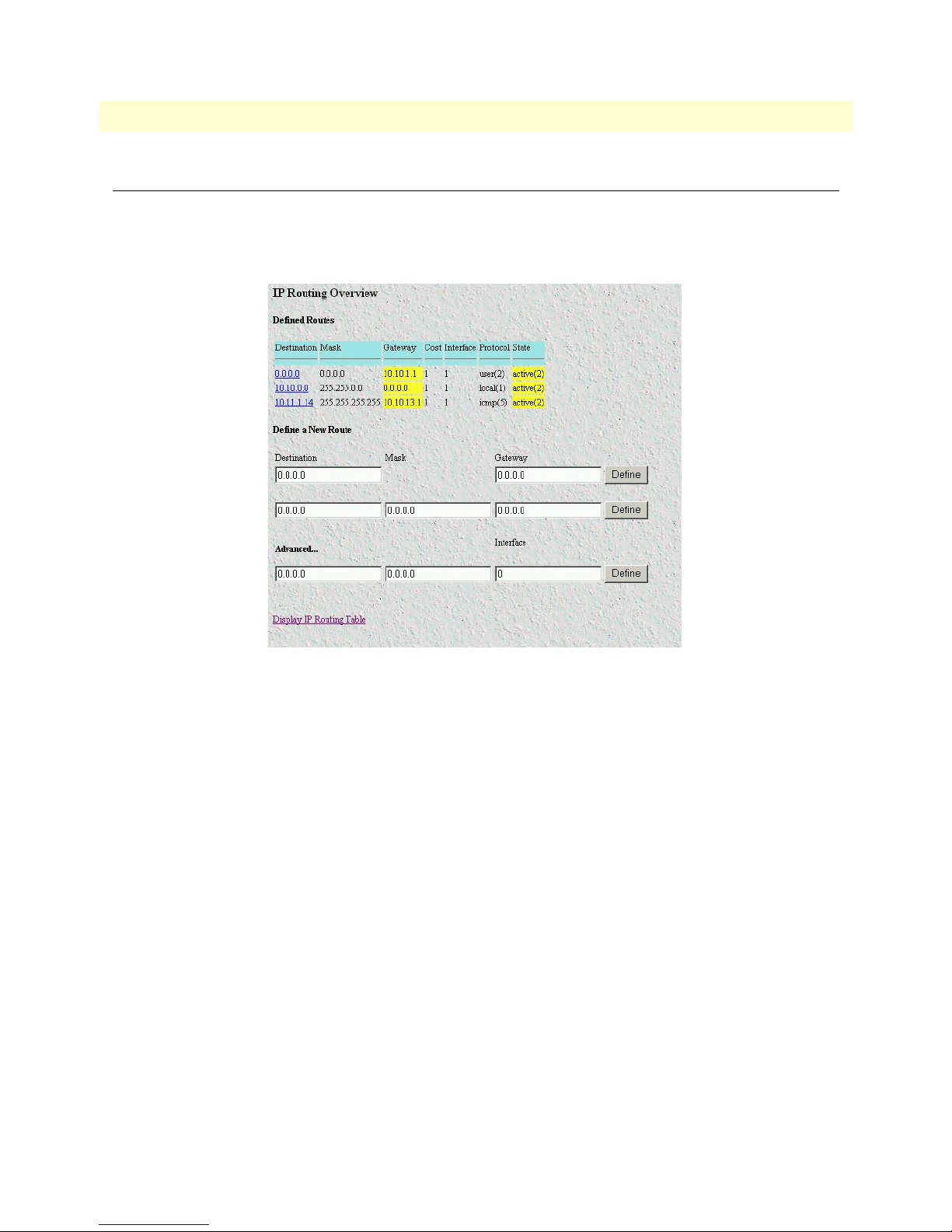
8 • IP 6511RC Matrix Switch Administrators’ Reference Guide
IP Routing Information window
The IP Routing Information window (see figure 33) displays information required to route IP datagrams,
including the IP address, subnet mask, next-hop router, and interface for each network interface defined in the
DACS.
Figure 33. IP Routing Information sub-page
The following paragraphs describe the contents of the IP Routing Information sub-page.
The IP Routing Information window also provides a link to the Forwarding Table window. The Forwarding
Table sub-page displays the IP forwarding parameters that the 6511RC’s operating system uses to make IP forwarding decisions. (see “Forwarding Table” on page 66).
Destination (genRouteDest)
The destination IP address of this route. An entry with a value of 0.0.0.0 is considered a default route. Multiple
routes to a single destination can appear in the table, but access to such multiple entries is dependent on the
table-access mechanisms defined by the network management protocol in use.
Each IP address displayed in the Destination column of the table also functions as a link to the Route Destination window. To view or modify next-hop routing information for a selected destination address, click on the
Address hyperlink in the Destination column. For more information about modifying next-hop routing information settings, refer to “Route Destination window” on page 64.
Mask (genRouteMask)
Indicates the mask to be logical-ANDed with the destination address before being compared to the value in the
ipRouteDest field. For those systems that do not support arbitrary subnet masks, an agent constructs the value
62 IP Routing Information window
Page 73

6511RC Matrix Switch Administrators’ Reference Guide 8 • IP
of the ipRouteMask by determining whether the value of the correspondent ipRouteDest field belongs to a
Class A, B, or C network, and then using the appropriate mask from table 3.
Table 3. Masks
Mask Network
255.0.0.0 class-A
255.255.0.0 class-B
255.255.255.0 class-C
Gateway (genRouteGateway)
Specifies the IP address to which the packets should be forwarded.
Cost (genRouteCost)
This is the cost of the route as defined by RIP standards. Cost is sometimes considered to be number of hops.
A cost of 16 is considered to be infinite. A cost can be given to user-entered routes so their preference in relation to learned routes can be calculated.
Interface (genRouteIfIndex)
The index value that identifies the local interface through which the next hop of this route should be reached.
The interface identified by a particular value of this index is the same interface as identified by the same value
of ifIndex. This may be zero in the case that the route is not active or no interface could be found which has
access to the gateway.
Protocol (genRouteProto)
The mechanism by which this route was learned is defined by protocol. The parameters are:
• unknown(0)
• local(1)—Added by O/S to support an interface
• user(2)—Added through row creation in this MIB
• rip(4)—Added by reception of a RIP packet
• icmp(5)—Added by reception of an ICMP packet
• radius(6)—Provided in a RADIUS response packet
State (RouteState)
• invalid(1)—This setting deletes the route.
• active(2)—A valid route is in use.
• nopath(3)—No route is available to the specified gateway. The gateway is not known to local networks.
• agedout(4)—Invalid route (soon to be removed).
• costly(5)—A valid route, but not in use because of it’s higher cost.
IP Routing Information window 63
Page 74

8 • IP 6511RC Matrix Switch Administrators’ Reference Guide
Add a route:
This portion of the IP Routing Information window is where you can add a new route to the IP Routing Information table. Fill in the Destination (genRouteDest), Mask (genRouteMask), and Gateway (genRouteGateway) information, then click Define.
Destination (ipRouteDest)
The destination IP address of this route. An entry with a value of 0.0.0.0 is considered a default route. Multiple
routes to a single destination can appear in the table, but access to such multiple entries is dependent on the
table-access mechanisms defined by the network management protocol in use.
Mask (ipRouteMask)
Indicates the mask to be logical-ANDed with the destination address before being compared to the value in the
ipRouteDest field. For those systems that do not support arbitrary subnet masks, an agent constructs the value
of the ipRouteMask by determining whether the value of the correspondent ipRouteDest field belongs to a
Class A, B, or C network, and then using the appropriate mask from table 3 on page 63.
Gateway (genRouteGateway)
Specifies the IP address to which the packets should be forwarded.
Advanced…
Enables a route to be attached to an interface. Packets to a network will be routed to that interface, allowing
the gateway IP address to be dynamic. Fill in the Destination (genRouteDest), Mask (genRouteMask), and
Inter-face (genRouteIfIndex) information, then click Define.
Destination (ipRouteDest)
The destination IP address of this route. An entry with a value of 0.0.0.0 is considered a default route. Multiple
routes to a single destination can appear in the table, but access to such multiple entries is dependent on the
table-access mechanisms defined by the network management protocol in use.
Mask (ipRouteMask)
Indicates the mask to be logical-ANDed with the destination address before being compared to the value in the
ipRouteDest field. For those systems that do not support arbitrary subnet masks, an agent constructs the value
of the ipRouteMask by determining whether the value of the correspondent ipRouteDest field belongs to a
Class A, B, or C network, and then using the appropriate mask from table 3 on page 63.
Gateway (genRouteGateway)
Specifies the IP address to which the packets should be forwarded.
Route Destination window
The Route Destination sub-page (see figure 34) displays the next-hop routing parameters for the single destination address displayed in the page title to display the Route Destination window, on the IP Routing Information page, identify the destination address you wish to view then click the address link.
64 Route Destination window
Page 75

6511RC Matrix Switch Administrators’ Reference Guide 8 • IP
Figure 34. Routing Destination window
The following paragraphs describe the parameters displayed on the The Route Destination sub-page.
Route Destination (genRouteDest)
The destination IP address of this route. An entry with a value of 0.0.0.0 is considered a default route. Multiple
routes to a single destination can appear in the table, but access to such multiple entries is dependent on the
table-access mechanisms defined by the network management protocol in use.
Mask (genRouteMask)
Indicates the mask to be logical-ANDed with the destination address before being compared to the value in the
ipRouteDest field. For those systems that do not support arbitrary subnet masks, an agent constructs the value
of the ipRouteMask by determining whether the value of the corresponding ipRouteDest field belongs to a
Class A, B, or C network, and then using the appropriate mask from table 3 on page 63.
Interface (genRouteIfIndex)
The index value which uniquely identifies the local interface through which the next hop of this route should
be reached. The interface identified by a particular value of this index is the same interface as identified by the
same value of ifIndex.
Protocol (genRouteProto)
The routing mechanism via which this route was learned. Inclusion of values for gateway routing protocols is
not intended to imply that hosts must support those protocols.
• unknown(0)
• local(1)—Added by the DACS to support an interface.
• user(2)—Added by an administrator on the IP Routing Information table or via SNMP management tools.
• dspf(3)—Not currently implemented.
• rip(4)—Learned via reception of RIP packet.
• icmp(5)—Learned via reception of ICMP packet.
Seconds Since Updated (genRouteAge)
The number of seconds since this route was last updated or otherwise determined to be correct.
Route Destination window 65
Page 76

8 • IP 6511RC Matrix Switch Administrators’ Reference Guide
Tag (genRouteTag)
An identifier associated with the route. This can have different meanings depending on the protocol. For example, this gives the tag that was passed with a learned RIP route.
Gateway (genRouteGateway)
Specifies the IP address to which the packets should be forwarded.
Cost (genRouteCost)
This is the cost of the route as defined by RIP standards. Cost is sometimes considered to be number of hops.
A cost of 16 is considered to be infinite. A cost can be given to user-entered routes so their preference in relation to learned routes can be calculated.
State (genRouteState)
Defines the state which a route may be in during its lifetime.
• invalid(1)—This setting deletes the route.
• active(2)—A valid route is in use.
• nopath(3)—No route is available to the specified gateway. The gateway is not known to local networks.
• agedout(4)—Invalid route (soon to be removed).
• costly(5)—A valid route, but not in use because of its higher cost.
Forwarding Table
The Forwarding Table window (see figure 35) displays the IP forwarding parameters for all routes in the
6511RC’s forwarding table. To display the Forwarding Table window, on the IP Routing Information subpage, click the O/S forwarding table link.
Figure 35. Forwarding Table window
Destination (ipRouteDest)
The destination IP address of this route. An entry with a value of 0.0.0.0 is considered a default route. Multiple
routes to a single destination can appear in the table, but access to such multiple entries is dependent on the
table-access mechanisms defined by the network management protocol in use.
Mask (ipRouteMask)
Indicates the mask to be logical-ANDed with the destination address before being compared to the value in the
ipRouteDest field. For those systems that do not support arbitrary subnet masks, an agent constructs the value
of the ipRouteMask by determining whether the value of the correspondent ipRouteDest field belongs to a
Class A, B, or C network, and then using the appropriate mask from table 3 on page 63.
66 Forwarding Table
Page 77

6511RC Matrix Switch Administrators’ Reference Guide 8 • IP
Next Hop (ipRouteNextHop)
The IP address of the next hop of this route. (In the case of a route bound to an interface which is realized via
a broadcast media, the value of this field is the agent's IP address on that interface.)
Interface (ipRouteIfIndex)
The index value that identifies the local interface through which the next hop of this route should be reached.
The interface identified by a particular value of this index is the same interface as identified by the same value
of ifIndex.
Type (ipRouteType)
One of the following route types:
• other(1)—none of the following
• invalid(2)—an invalidated route
• direct(3)—route to directly connected (sub-)network
• indirect(4)—route to a non-local host/network/sub-network
Note The values direct(3) and indirect(4) refer to the notion of direct and indirect
routing in the IP architecture. Setting this object to the value invalid(2) has the
effect of invalidating the corresponding entry in the ipRouteTable object. That
is, it effectively disassociates the destination identified with said entry from the
route identified with said entry. It is an implementation-specific matter as to
whether the agent removes an invalidated entry from the table. Accordingly,
management stations must be prepared to receive tabular information from
agents that corresponds to entries not currently in use. Proper interpretation of
such entries requires examination of the relevant ipRouteType object.
Protocol (ipRouteProto)
The routing mechanism via which this route was learned. Inclusion of values for gateway routing protocols is
not intended to imply that hosts must support those protocols.
• unknown(0)
• local(1)—Added by the DACS to support an interface.
• user(2)—Added by an administrator on the IP Routing Information table or via SNMP management tools.
• dspf(3)—Not currently implemented.
• rip(4)—Learned via reception of RIP packet.
• icmp(5)—Learned via reception of ICMP packet.
Info (ipRouteInfo)
A reference to MIB definitions specific to the particular routing protocol which is responsible for this route, as
determined by the value specified in the route’s ipRouteProto value. If this information is not present, its value
should be set to the OBJECT IDENTIFIER { 0 0 }, which is a syntactically valid object identifier, and any
conformant implementation of ASN.1 and BER must be able to generate and recognize this value.
Forwarding Table 67
Page 78

8 • IP 6511RC Matrix Switch Administrators’ Reference Guide
Address Translation Information window
The Address Translation Information window (see figure 36) displays the contents of the 6511RC’s logical-tophysical address translation table. The 6511RC uses the table to resolve the correspondence between a logical
IP network address and a physical Media Access Control (MAC) address.
Note Some interface types do not use translation tables to determine address
equivalences (for example, DDN-X.25 uses an algorithmic method). If the
Address Translation table is empty (there are no entries), that indicates that
none of the 6511RC’s interfaces are using an address translation table.
Figure 36. Address Translation Information window
The following sections describe the information displayed on the Address Translation Information window.
Interface (ipNetToMediaIfIndex)
Each entry contains one IP address to physical address equivalence.
Net Address (ipNetToMediaNetAddress)
The IP address corresponding to the media-dependent physical address.
Physical (ipNetToMediaPhysAddress)
The media-dependent physical address.
Type (ipNetToMediaType)
The type of mapping. Setting this object to the value invalid(2) has the effect of invalidating the corresponding
entry in the ipNetToMediaTable. That is, it effectively disassociates the interface identified with said entry
from the mapping identified with said entry. It is an implementation-specific matter as to whether the agent
removes an invalidated entry from the table. Accordingly, management stations must be prepared to receive
68 Address Translation Information window
Page 79

6511RC Matrix Switch Administrators’ Reference Guide 8 • IP
tabular information from agents that corresponds to entries not currently in use. Proper interpretation of such
entries requires examination of the relevant ipNetToMediaType object.
• other(1)—None of the following
• invalid(2)—An invalidated mapping
• dynamic(3)
• static(4)
Address Translation Information window 69
Page 80

8 • IP 6511RC Matrix Switch Administrators’ Reference Guide
70 Address Translation Information window
Page 81

Chapter 9 IP Filtering
Chapter contents
Introduction..........................................................................................................................................................72
Defining a filter .....................................................................................................................................................72
Modify Filter.........................................................................................................................................................73
Name (filterIpName) ......................................................................................................................................73
Direction (filterIpDirection) ...........................................................................................................................73
Action (filterIpAction) ....................................................................................................................................74
Source IP ........................................................................................................................................................74
Comparison (filterIpSourceAddressCmp) ..................................................................................................74
Address (filterIpSourceIp) .........................................................................................................................74
Mask (filterIpSourceMask) ........................................................................................................................74
Destination IP ................................................................................................................................................75
Comparison (filterIpDestinationAddressCmp) ..........................................................................................75
Address (filterIpDestinationIp) ..................................................................................................................75
Mask (filterIpDestinationMask) ................................................................................................................75
Source Port .....................................................................................................................................................75
Comparison (filterIpSourcePortCmp) .......................................................................................................75
Port (filterIpSourcePort) ...........................................................................................................................75
Destination Port .............................................................................................................................................75
Comparison (filterIpDestinationPortCmp) ...............................................................................................75
Port (filterIpDestinationPort) ....................................................................................................................76
Protocol (filterIpProtocol) ...............................................................................................................................76
TCP Established (filterIpTcpEstablished) .......................................................................................................76
Default for dialin (filterIpDefaultDialin) ........................................................................................................76
An example of using a filter ...................................................................................................................................76
Deleting a filter......................................................................................................................................................78
71
Page 82

9 • IP Filtering Model 6511RC Matrix Switch Administrators’ Reference Guide
Introduction
The access server software provides an IP filtering system that enables you to set up security as well as to provision services for selected customers. While IP filters are typically thought of as a security measure, many providers wish to limit some services a customer may have access to. These could include such things as limited
access only to an e-mail server or proxy server. IP filters also include the ability to encapsulate all packets
received on the specified dialup link in an extra IP header using RFC 2003. This would allow packets on a dialup link to be tunneled to a specific host.
Each filter is a defined list of parameters based upon attributes in the IP, TCP, and UDP headers. There are two
major steps to filter creation: first defining the filter, then applying it to a user connection. The same filter can
be shared by several users.
The access server enables 20 separate filters to be defined, of which up to 10 can be used on a single user connection. A single filter can be assigned to a user via the Static Users Authentication. Multiple filters can be
assigned by using the RADIUS Filter-Id attribute.
Filters can be configured with default settings that are used for all dial-in sessions. If any filters are applied
through either RADIUS or the Static User filter parameter, then all of the dial-in defaults will be disabled and
only the specified filters will be applied.
Click on Filter IP under the Configuration Menu to display the IP Filtering Overview main window (see
figure 37). The following sections describe each of the parameters found in the IP Filtering Overview main win-
dow.
Figure 37. IP Filtering Overview main window
Defining a filter
To define a new filter, select a number and a name, then click on the Define button to submit the request. The
number and name must not already exist in the IP FILTER list, and the number must be an integer between 1
and 20. To delete a filter, enter just the ID number without a name and click on the Define button.
72 Introduction
Page 83
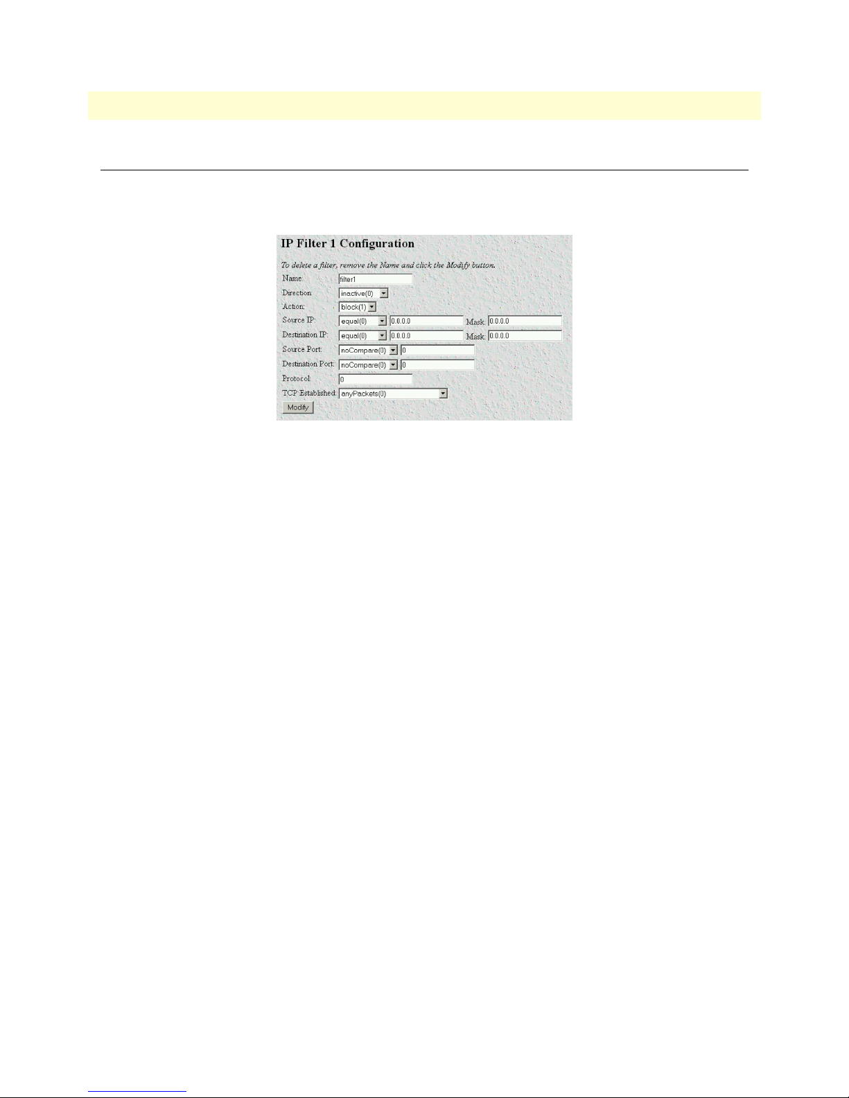
Model 6511RC Matrix Switch Administrators’ Reference Guide 9 • IP Filtering
Modify Filter
After entering a number and name, click on the name of the filter to display the filter parameters window (see
figure 38).
Figure 38. Filter IP parameters window
The following parameters can be configured for IP Filtering:
Note Any changes to a filter take place immediately. This can aid in troubleshoot-
ing a filter profile while the user is online.
Name (filterIpName)
This is the name of the filter
Direction (filterIpDirection)
Specifies the direction of the filter (that is, whether it applies to data packets inbound or outbound from the
access server). The filter only applies to dial in users, users on other interfaces (that is, Ethernet, Frame Relay,
and so on) are not affected. The following options are available:
• inactive(0)—Disables filter operation
• inbound(1)—Relates to packets coming into the access server
• outbound(2)—Relates to packets leaving the access server
• both(3)—Specifies both inbound and outbound operation
Note Enabling or disabling filters that are applied to dial-in users who are currently
online will immediately change those users’ ability to send or receive packets,
depending on the changes that are made to the filters.
Modify Filter 73
Page 84

9 • IP Filtering Model 6511RC Matrix Switch Administrators’ Reference Guide
Action (filterIpAction)
Specifies the action to take on a packet whether to block or pass the packet. The following options are available:
• pass(0)—If pass is selected, checking will continue on to other filters until either a match occurs, a block
occurs, or there are no more filters remaining to check.
Note If there are any applied PASS filters, then at least one of them must match or
the packet will be dropped.
• block(1)—If a filter has block set and the filter matches the block, the packet is discarded and no further
processing is done.
• wrap(2)—All packets received on the specified dialup link will be encapsulated in an extra IP header as
defined in RFC2003. The destination IP address of the wrapper is given by the destination IP setting in the
filter. The source IP address of the wrapper is the ethernet address of the remote access server.
All wrap filters are inbound only.
Note Block filters take priority, therefore any applied and matching block filters
will drop the packet. Next, pass filters are examined, if PASS filters have been
defined, then at least one of them must match or else the packet will be
dropped. After the block and pass filters are examined, the WRAP filter, if it
exists, will be applied.
Source IP
Applies the filter action based on the results of the stated comparison to the IP address and subnet mask.
Comparison (filterIpSourceAddressCmp)
• equal(0)—apply the action of the filter if the Source IP equals the IP address/subnet mask combination
supplied
• notEqual(1)—apply the action of the filter if the Source IP does not equal the IP address/subnet mask com-
bination supplied
Address (filterIpSourceIp)
The IP address to which the filter will compare the source IP address.
Mask (filterIpSourceMask)
The subnet mask the filter will apply to the source IP address to make the comparison.
Note These fields are ignored unless either the IP address or Mask have been
entered. Bit positions that are set to 1 will be compared and 0s will be
ignored. Thus, a setting of 0.0.0. will have the effect of disabling source IP
address comparison.
74 Modify Filter
Page 85

Model 6511RC Matrix Switch Administrators’ Reference Guide 9 • IP Filtering
Destination IP
Applies the action based on the results of the stated comparison to the IP address and subnet mask.
Comparison (filterIpDestinationAddressCmp)
• equal(0) – apply the action of the filter if the destination IP equals the IP address/subnet mask combination
supplied
• notEqual(1) – apply the action of the filter if the destination IP does not equal the IP address/subnet mask
combination supplied
Address (filterIpDestinationIp)
The IP address the filter will apply to the destination IP address to make the comparison.
Mask (filterIpDestinationMask)
The subnet mask the filter will apply to the destination IP address to make the comparison.
Note These fields are ignored unless either the IP address or Mask have been
entered. Bit positions that are set to 1 will be compared and 0s will be
ignored. Thus, a setting of 0.0.0. will have the effect of disabling destination
IP address comparison.
Source Port
Applies the filter action based on the stated comparison to the source port number (TCP or UDP)
Comparison (filterIpSourcePortCmp)
• noCompare(0) – no comparison to the source port in the IP packet
• equal(1) – the source port in the IP action must be the same for the filter to be applied
• lessThan(2) – the source port in the IP packet must be less than the source port specified for the filter to be
applied
• greaterThan(3) – the source port in the IP packet must be greater than the source port specified for the filter
to be applied
Port (filterIpSourcePort)
The port number to be compared to the source port in the IP packet
Destination Port
Applies the filter action based on the stated comparison to the destination port number
Comparison (filterIpDestinationPortCmp)
• noCompare(0) – no comparison to the destination port in the IP packet
• equal(1) – the destination port in the IP action must be the same for the filter to be applied
• lessThan(2) – the destination port in the IP packet must be less than the source port specified for the filter
to be applied
Modify Filter 75
Page 86

9 • IP Filtering Model 6511RC Matrix Switch Administrators’ Reference Guide
• greaterThan(3) – the destination port in the IP packet must be greater than the source port specified for the
filter to be applied
Port (filterIpDestinationPort)
The port number to be compared to the destination port in the IP packet
Protocol (filterIpProtocol)
Specifies the IP Protocol number to use for filtering. Some examples of protocol numbers are 1 for ICMP; 6 for
TCP; and 17 for UDP. A list of protocol numbers can be found in RFC 1340. A setting of 0 disables processing based on protocol number.
TCP Established (filterIpTcpEstablished)
Specifies whether the filter should match only those packets which indicate in the TCP header flags that the
connection is established. The following choices are available:
• anyPackets(0)—Applies the filter to all packets
• onlyEstablishedConnections(1)—Only applies the filter to established TCP connections
Default for dialin (filterIpDefaultDialin)
This option applies the filter to as a default filter for all dial-in users. If another filter is specified, either in
RADIUS or in the static user profiles, then all dial-in defaults are disabled and only the specified filters are
applied. The following choices are available:
• no(0)
• applyToDialin(1)
An example of using a filter
All customers are limited to the local mail server (mail.internal.com) and an internal website
(www.internal.com).
• The IP address for mail.internal.com is: 192.10.10.1
• for: www.internal.com is: 192.10.10.2
• DNS server for name resolution is 192.10.10.1.
The filters needed:
• ID:1
– Name: Mail Server
– Direction: inbound
– Action: pass
– Source IP and mask: not set
– Destination IP: 192.10.10.1 mask: 255.255.255.255
– Source Port: no compare
76 An example of using a filter
Page 87

Model 6511RC Matrix Switch Administrators’ Reference Guide 9 • IP Filtering
– Destination Port: equal 110 for POP3 or 25 for SMTP
– Protocol: not set
– TCP Established: anyPackets
– Default for dial-in: apply to Dial-in
• ID:2
– Name: WebSite
– Direction: inbound
– Action: pass
– Source IP and mask: not set
– Destination IP: 192.10.10.2 mask: 255.255.255.255
– Source Port: no compare
– Destination Port: equal 80
– Protocol: not set
– TCP Established: anyPackets
– Default for dial-in: apply to Dial-in
• ID:3
– Name: DNS
– Direction: inbound
– Action: pass
– Source IP and mask: not set
– Destination IP: 192.10.10.1 mask: 255.255.255.255
– Source Port: no compare
– Destination Port: equal 53
– Protocol: not set
– TCP Established anyPackets
– Default for dial-in: apply to Dial-in
Note If the DNS filter was not created, then users would have to use IP addresses
to access the web server and the mail server.
Now if you wanted to add the ability to ping to test the dial-in users connectivity to the network, the following
filter would be created:
• ID:4
• Name: PING
An example of using a filter 77
Page 88

9 • IP Filtering Model 6511RC Matrix Switch Administrators’ Reference Guide
• Direction: both
• Action: pass
• Source IP and mask: not set
• Destination IP and mask: not set
• Source Port: no compare
• Destination Port: no compare
• Protocol: 1
• TCP Established: anyPackets
• Default for dial-in: apply to Dial-in
Note This would also allow traceroute to work.
Deleting a filter
To delete a filter, do the following:
1. Type the ID number of the filter you want to delete in the ID field (see figure 37 on page 72).
2. Leaving the Name field blank, click on the Define button to delete the filter.
78 Deleting a filter
Page 89

Chapter 10 RIP Version 2
Chapter contents
Introduction..........................................................................................................................................................80
RIP Version 2 Overview main window..................................................................................................................80
RIP status table ...............................................................................................................................................81
RIP Configuration table ..................................................................................................................................81
Adding a RIP Address table .............................................................................................................................82
RIP Version 2 (Status)...........................................................................................................................................83
Subnet IP Address (rip2IfStatAddress) ............................................................................................................83
Bad Packets (rip2IfStatRcvBadPackets) ...........................................................................................................83
Bad Routes (rip2IfStatRcvBadRoutes) ............................................................................................................83
Sent Updates (rip2IfStatSentUpdates) .............................................................................................................83
Status (rip2IfStatStatus) ..................................................................................................................................83
RIP Version 2 (Configuration) window.................................................................................................................83
Address (rip2IfConfAddress) ...........................................................................................................................84
Domain (rip2IfConfDomain) .........................................................................................................................84
Authentication Type (rip2IfConfAuthType) ...................................................................................................84
Authentication Key (rip2IfConfAuthKey) .......................................................................................................84
Metric (rip2IfConfDefaultMetric) ..................................................................................................................85
Status (rip2IfConfStatus) ................................................................................................................................85
79
Page 90

10 • RIP Version 2 Model 6511RC Matrix Switch Administrators’ Reference Guide
Introduction
The 6511RC provides support for Routing Information Protocol (RIP) Version 2. The 6511RC RIP version 2
subsystem provides management information in the form of RIP Version 2 addresses, parameters, and statistics. Managing the RIP version 2 subsystem involves defining RIP Version 2 addresses and parameters, and
monitoring RIP Version 2 parameters and statistics on TCP.
All object identifiers described in this chapter comply with those contained in RFC 1724: RIP Version 2 MIB
Extension.
RIP Version 2 Overview main window
The RIP Version 2 Overview main window (see figure 39) provides the means for you to manage the 6511RC’s
RIP Version 2 subsystem. The window displays the current values of certain RIP Version 2 operating parameters and statistics, and provides the means for you to add IP addresses to the 6511RC’s RIP Version 2 table.
The window displays information in the following three tables:
• The RIP status section at the top of the window.
• The RIP Configuration section in the middle of the window.
• The Add a RIP Address section at the bottom of the window.
To display the RIP Version 2 Overview main window, on the 6511RC Configuration Menu pane, click on the
RIP Version 2 link.
80 Introduction
Figure 39. RIP Version 2 Overview window
Page 91

Model 6511RC Matrix Switch Administrators’ Reference Guide 10 • RIP Version 2
The RIP Version 2 Overview main window provides links to the RIP Version 2 Statistics and Parameters win-
dows, as shown in figure 40.
RIP Version 2 Summary
RIP Version 2
Statistics
RIP Version 2
Parameters
Figure 40. RIP Version 2 windows map
The following sections describe the contents of the tables displayed on the RIP Version 2 main window.
RIP status table
• Route Changes Made (rip2GlobalRouteChanges)—The number of route changes made to the IP Route
Database by RIP. This does not include the refresh of a route's age.
• Responses Sent (rip2GlobalQueries)—The number of responses sent to RIP queries from other systems.
RIP Configuration table
• Statistics hyperlink—Clicking on the Statistics link displays the RIP Version 2 Statistics window (see “RIP
Version 2 (Status)” on page 83). For each subnet IP address in the 6511RC’s RIP Version 2 table, the RIP
Version 2 Statistics window displays the RIP route status and statistical counts for Bad Packets, Bad Routes,
and Sent Updates.
• Address (xxx.xxx.xxx.xxx) [rip2IfConfAddress]—Each IP Address in the table defines a single routing
domain in a single subnet for the 6511RC—to use when making RIP routing decisions.
Note Each IP Address displayed in the RIP Version 2 table also functions as a
hyperlink to the RIP Version 2 Parameters window (see section “RIP Version
2 (Configuration) window” on page 83). You can use the RIP Version 2
Parameters window to view and modify the parameters for a single address.
Initially, because the 6511RC RIP Version 2 table is empty, the RIP Version 2 main window will not display
any address hyperlinks. You can use the Adding a RIP Address table to add one more IP addresses to the
6511RC RIP Version 2 table (see Adding a RIP address). Once you have defined a RIP version 2 address,
that address will appear in the table. To view the configurable parameters for an address, click on the
Address hyperlink under the Address column to display the RIP Version 2 Parameters window (see “RIP
Version 2 (Status)” on page 83).
• Send (rip2IfConfSend)—Send is what the router sends on this interface. ripVersion 1 implies sending RIP
updates compliant with RFC 1058 rip1Compatible(3), and ripVersion2(4). The following options are available:
- doNotSend(1)
RIP Version 2 Overview main window 81
Page 92

10 • RIP Version 2 Model 6511RC Matrix Switch Administrators’ Reference Guide
- ripVersion1(2)
- rip1Compatible (3)—rip1Compatible implies broadcasting RIP-2 updates using RFC 1058 route sub-
sumption rules
- ripVersion2 (4)—ripVersion2 implies multicasting RIP-2 updates
• Receive (rip2IfConfReceive)—This indicates which version of RIP updates are to be accepted.
- rip1 (1)
- rip2 (2)
- rip1OrRip2 (3)
- doNotRecieve (4)
Note rip2 and rip1OrRip2 implies reception of multicast packets.
Adding a RIP Address table
To add a RIP address to the 6511RC’s RIP Version 2 table, do the following:
1. Enter the IP network address of the interface on the 6511RC that you want to enable RIP. This will be the
LAN IP address, in other words, the IP address of the 6511RC. This is not the IP address of the device you
want to direct RIP packets to.
2. Enter the protocol version to be used for sending RIP packets. The following choices are available:
– doNotSend (1)
– ripVersion1 (2)—ripVersion 1 implies sending RIP updates compliant with RFC 1058
– rip1Compatible (3)—rip1Compatible implies broadcasting RIP-2 updates using RFC 1058 route sub-
sumption rules
– ripVersion2 (4)—ripVersion2 implies multicasting RIP-2 updates
3. Enter the protocol version to be used for receiving RIP packets. The following choices are available:
– rip1 (1)—ripVersion 1 implies sending RIP updates compliant with RFC 1058
– rip2(2)—rip1Compatible implies broadcasting RIP-2 updates using RFC 1058 route subsumption rules
– rip1OrRip2(3)
– doNotReceive(4)
Note rip2 and rip1OrRip2 implies reception of multicast packets.
4. Click on Define.
Note To delete the RIP address, click on the IP Address under the column
named Address. Select Status to be invalid(2) and click on Define.
To view and modify additional configurable parameters for the RIP address, click on the Address hyperlink to
display the RIP Version Configuration window.
82 RIP Version 2 Overview main window
Page 93

Model 6511RC Matrix Switch Administrators’ Reference Guide 10 • RIP Version 2
RIP Version 2 (Status)
For each subnet IP address defined in the 6511RC’s RIP Version 2 table, the RIP Version 2 (Status) window
(see figure 42) displays the RIP route status and the following statistical counts:
• Bad Packets
• Bad Routes
• Sent Updates
To display the RIP Version 2 (Status) window, on the RIP Version 2 main window, click the Statistics… link.
Figure 41. RIP Version 2 (Status) window
The following sections describe the information displayed on the RIP Version 2 (status) window.
Subnet IP Address (rip2IfStatAddress)
The IP Address of this system on the indicated subnet. For unnumbered interfaces, the value 0.0.0.N, where
the least significant 24 bits (N) is the ifIndex for the IP Interface in network byte order.
Bad Packets (rip2IfStatRcvBadPackets)
The number of RIP response packets received by the RIP process which were subsequently discarded for any
reason (e.g. a version 0 packet, or an unknown command type).
Bad Routes (rip2IfStatRcvBadRoutes)
The number of routes, in valid RIP packets, which were ignored for any reason (e.g. unknown address family,
or invalid metric).
Sent Updates (rip2IfStatSentUpdates)
The number of triggered RIP updates actually sent on this interface. This explicitly does NOT include full
updates sent containing new information.
Status (rip2IfStatStatus)
Displays whether the RIP status for the Subnet IP Address is valid or invalid. One of the following values will
be displayed:
• valid(1)—Data may be routed on this interface.
• invalid(2)—Effectively deletes this interface.
RIP Version 2 (Configuration) window
The RIP Version 2 (Configuration) window (see figure 42) displays the configurable parameters for the single
RIP routing domain defined by the IP Address displayed at the top of the table. You can use the RIP Version 2
RIP Version 2 (Status) 83
Page 94

10 • RIP Version 2 Model 6511RC Matrix Switch Administrators’ Reference Guide
Configuration window to view and modify the parameters for the routing domain. The configurable parameters are Domain, Authentication Type, Authentication Key, Send, Receive, Metric, and Status.
Do the following to display the RIP Version 2 Configuration -window:
1. On the RIP Version 2 main window, in the RIP Configuration table, under the Address column, identify
the RIP address you wish to view.
2. Click the Address link.
Figure 42. RIP Version 2 (Configuration) window
The following sections describe the configurable parameters displayed on the RIP Version 2 Configuration
window.
Address (rip2IfConfAddress)
The IP Address of this system on the indicated subnet. For unnumbered interfaces, the value 0.0.0.N, where
the least significant 24 bits (N) is the ifIndex for the IP Interface in network byte order.
Domain (rip2IfConfDomain)
Value inserted into the Routing Domain field of all RIP packets sent on this interface.
Authentication Type (rip2IfConfAuthType)
The type of Authentication used on this interface.
• noAuthentication (1)
• simplePassword (2)
Authentication Key (rip2IfConfAuthKey)
This value is used as the Authentication Key whenever Authentication Type (rip2IfConfAuthType) has a value
other than noAuthentication(1). A modification of Authentication Type does not change the value of Authen-
84 RIP Version 2 (Configuration) window
Page 95

Model 6511RC Matrix Switch Administrators’ Reference Guide 10 • RIP Version 2
tication Key. If the Authentication Key string is shorter than 16 octets, it will be left justified, then padded to
16 octets with nulls (0x00) on the right.
Reading this object always results in an octet string of length zero. Authentication may not be bypassed by
reading the MIB object.
Metric (rip2IfConfDefaultMetric)
This variable indicates the metric that is to be used for the default route entry in RIP updates originated on this
interface. A value of zero indicates that no default route should be originated; in this case, a default route via
another router may be propagated.
Status (rip2IfConfStatus)
Writing invalid has the effect of deleting this interface.
• valid (1)
• invalid (2)
RIP Version 2 (Configuration) window 85
Page 96

10 • RIP Version 2 Model 6511RC Matrix Switch Administrators’ Reference Guide
86 RIP Version 2 (Configuration) window
Page 97

Chapter 11 SNMP
Chapter contents
Introduction..........................................................................................................................................................88
SNMP window......................................................................................................................................................88
MIB Links ......................................................................................................................................................89
Configurable Parameter—Authentication Failure Traps (snmpEnableAuthenTraps) ......................................89
Saving your work ......................................................................................................................................89
SNMP Statistics table .....................................................................................................................................89
SNMP Statistics—In ......................................................................................................................................89
Packets (snmpInPkts) ................................................................................................................................89
Bad Version (snmpInBadVersions) ............................................................................................................89
Bad Community Names (snmpInBadCommunityNames) ........................................................................89
Bad Community Uses (snmpInBadCommunity Uses) ..............................................................................89
ASN ParseErrors (snmpInASNParseErrs) ..................................................................................................90
Error Status “Too Big” (snmpInTooBigs) .................................................................................................90
No Such Names (snmpInNoSuchNames) .................................................................................................90
Bad Values (snmpInBadValues) ................................................................................................................90
Error Status “Read Only” (snmpInReadOnlys) .........................................................................................90
Generated Errors (snmpInGenErrs) ..........................................................................................................90
Get/Get Next Variables (snmpInTotalReqVars) ........................................................................................90
Set Variables (snmpInTotalSetVars) ..........................................................................................................90
Get Requests (snmpInGetRequests) ..........................................................................................................90
Get Next Requests (snmpInGetNexts) ......................................................................................................90
Set Requests (snmpInSetRequests) ............................................................................................................90
Get Responses (snmpInGetResponses) ......................................................................................................91
Traps (snmpInTraps) ................................................................................................................................91
SNMP Statistics—Out ...................................................................................................................................91
Out Packets (snmpOutPkts) .....................................................................................................................91
Error Status “Too Big” (snmpOutTooBigs) ..............................................................................................91
No Such Names (snmpOutNoSuchNames) ..............................................................................................91
Bad Values (snmpOutBadValues) .............................................................................................................91
Generated Errors (snmpOutGenErrs) .......................................................................................................91
Get Requests (snmpOutGetRequests) .......................................................................................................91
Get Next Requests (snmpOutGetNexts) ...................................................................................................91
Set Requests (snmpOutSetRequests) .........................................................................................................91
Get Responses (snmpOutGetResponses) ...................................................................................................91
Traps (snmpOutTraps) .............................................................................................................................91
87
Page 98

11 • SNMP Model 6511RC Matrix Switch Administrators’ Reference Guide
Introduction
The 6511RC SNMP subsystem provides management and statistical information about the operation of the
SNMP protocol on the 6511RC.
RFC 3418: Management Information Base (MIB) for the Simple Network Management Protocol (SNMP) provides
detailed information about the SNMP MIB variables that the 6511RC SNMP subsystem utilizes.
SNMP window
The SNMP Overview window (see figure 43), contains three sections that provide the following functions::
• MIB Links—Three hyperlinks to the SNMP sub-windows shown in the diagram below to display the MIB
diagrams for the Corporate, Enterprise and Products MIBs. When you click one of the MIB hyperlinks,
your browser will download and display the document containing the diagram for that MIB.
• SNMP Parameters—By selecting a value for this configurable parameter, you can enable or disable sending
SNMP traps to report SNMP authentication failures.
• SNMP Statistics—displays statistics about the operation of the SNMP protocol on the 6511RC.Two col-
umns display the statistical counts for incoming and outgoing SNMP messages.
To display the SNMP Overview window on the 6511RC configuration menu pane, click the SNMP hyperlink.
88 Introduction
Figure 43. SNMP Overview window
Page 99

Model 6511RC Matrix Switch Administrators’ Reference Guide 11 • SNMP
MIB Links
Three hyperlinks provide access to the MIB diagrams for the Corporate, Enterprise and Products MIBs by
which the Matrix Switch SNMP protocol operates. When you click one of the MIB hyperlinks, the web
browser will request a location to save the MIB, then download and display the text file describing that MIB.
Configurable Parameter—Authentication Failure Traps (snmpEnableAuthenTraps)
This value indicates whether the SNMP agent process is permitted to generate authentication-failure traps.
The variable is global. This means that by being disabled, all authentication-failure traps are disabled.
The two options for this variable are:
• enabled(1)
• disabled(2)
Saving your work
Once you have modified the value of Authentication Failure Traps you must click the Modify button to save
your settings into volatile DRAM. Once you click the button, the 6511RC will implement the changes immediately.
Note To save your changes persistently, (i.e. through a 6511RC power cycle) you
must visit the 6511RC HOME page, and click the Record Current Configuration button. When you click the Record Current Configuration but-
ton, the 6511RC will copy the configuration currently stored in volatile
DRAM into non-volatile Flash memory for persistent storage.
SNMP Statistics table
The following sections describe the statistical counts displayed in the In and Out columns on the SNMP Statistics table.
SNMP Statistics—In
This section describes the statistical counts displayed in the In column on the SNMP window.
Packets (snmpInPkts)
The total number of Messages delivered to the SNMP entity from the transport service. Typically this would
be UDP since the SNMP engine sits on top of UDP
Bad Version (snmpInBadVersions)
The total number of SNMP Messages that were delivered to the SNMP protocol entity and were for an unsupported SNMP version.
Bad Community Names (snmpInBadCommunityNames)
The total number of SNMP Messages delivered to the SNMP protocol entity which used a SNMP community
name not known to said entity.
Bad Community Uses (snmpInBadCommunity Uses)
The total number of SNMP messages delivered to the SNMP protocol entity which represented an SNMP
operation which was not allowed by the SNMP community named in the message.
SNMP window 89
Page 100

11 • SNMP Model 6511RC Matrix Switch Administrators’ Reference Guide
ASN ParseErrors (snmpInASNParseErrs)
The total number of ASN.1 or BER errors encountered by the SNMP protocol entity when decoding received
SNMP messages.
Error Status “Too Big” (snmpInTooBigs)
The total number of SNMP PDUs that were delivered to the SNMP protocol entity and for which the value of
the error-status field is tooBig.
No Such Names (snmpInNoSuchNames)
The total number of SNMP PDUs that were delivered to the SNMP protocol entity and for which the value of
the error-status field is noSuchName.
Bad Values (snmpInBadValues)
The total number of SNMP PDUs that were delivered to the SNMP protocol entity and for which the value of
the error-status field is badValue.
Error Status “Read Only” (snmpInReadOnlys)
The total number of valid SNMP PDUs that were delivered to the SNMP protocol entity and for which the
value of the error-status field is readOnly. It should be noted that it is a protocol error to generate an SNMP
PDU which contains the readOnly value in the error-status field, as such this object is provided as a means of
detecting incorrect implementations of the SNMP.
Generated Errors (snmpInGenErrs)
The total number of SNMP PDUs that were delivered to the SNMP protocol entity and for which the value of
the error-status field is genErr.
Get/Get Next Variables (snmpInTotalReqVars)
The total number of MIB objects that have been retrieved successfully by the SNMP protocol entity as the
result of receiving valid SNMP Get-Request and Get-Next PDUs.
Set Variables (snmpInTotalSetVars)
The total number of MIB objects that have been altered successfully by the SNMP protocol entity as the result
of receiving valid SNMP Set-Request PDUs.
Get Requests (snmpInGetRequests)
The total number of SNMP Get-Request PDUs that have been accepted and processed by the SNMP
protocol entity.
Get Next Requests (snmpInGetNexts)
The total number of SNMP Get-Next PDUs that have been accepted and processed by the SNMP protocol
entity.
Set Requests (snmpInSetRequests)
The total number of SNMP Set-Request PDUs that have been accepted and processed by the SNMP protocol
entity.
90 SNMP window
 Loading...