

Page 1
Model 3224 Diamond Edge
G.SHDSL IpDSLAM
Model 6081RC EdgeRoute
Network Access Server
Applications Guide
Sales Office: +1 (301) 975-1000
Technical Support: +1 (301) 975-1007
E-mail: support@patton.com
WWW: www.patton.com
Document Number: 11002U5-001 Rev. B
Part Number: 07MD3224-AG
Revised: October 28, 2005
Page 2

Patton Electronics Company, Inc.
7622 Rickenbacker Drive
Gaithersburg, MD 20879 USA
tel: +1 (301) 975-1000
fax: +1 (301) 869-9293
support: +1 (301) 975-1007
web: www.patton.com
e-mail: support@patton.com
Trademarks
The term ForeFront is a registered trademark of Patton Electronics
Company in the United States and other countries.
Copyright
Copyright © 2004, Patton Electronics Company. All rights reserved.
Notice
The information in this document is subject to change without notice. Patton
Electronics assumes no liability for errors that may appear in this document.
The software described in this document is furnished under a license and may
be used or copied only in accordance with the terms of such license.
Page 3

Contents
About this guide .....................................................................................................................................................3
Audience................................................................................................................................................................. 3
Structure................................................................................................................................................................. 3
Typographical conventions used in this document.................................................................................................. 4
General conventions .........................................................................................................................................4
Mouse conventions ...........................................................................................................................................4
1 Introduction ................................................................................................................................................... 5
Overview .................................................................................................................................................................6
2 Physical layer configuration ............................................................................................................................ 9
Introduction..........................................................................................................................................................10
Physical layer characteristics...................................................................................................................................10
Configuring Model 3224 G.SHDSL parameters ...................................................................................................11
Configuring Model 6081RC H.110 parameters ....................................................................................................12
Defining H.110 channels ................................................................................................................................12
Defining H.110 ports, timeslots, and direction ...............................................................................................13
3 Bridged data application ............................................................................................................................... 17
Introduction..........................................................................................................................................................18
Basic assumptions..................................................................................................................................................20
Defaults.................................................................................................................................................................21
CPE configuration.................................................................................................................................................22
Initiating bridged Ethernet data communications..................................................................................................22
Modifying the factory default configuration ..........................................................................................................22
Logging in using the factory-default IP address ...............................................................................................23
Modifying the IP address for Ethernet interface A (optional) ..........................................................................24
Creating a bridge group.........................................................................................................................................25
PPP channel configuration ....................................................................................................................................27
Interface configuration ..........................................................................................................................................30
Alternate Interface Configuration for Model 6081RC .....................................................................................31
Verifying operation................................................................................................................................................32
Verifying bridged connection ..........................................................................................................................32
4 VLAN bridged connection............................................................................................................................. 35
Introduction..........................................................................................................................................................36
Attaching a VLAN ID to an Ethernet interface......................................................................................................36
Attaching a bridge interface to a VLAN module ....................................................................................................37
5 Routed application using RIP ....................................................................................................................... 39
Introduction..........................................................................................................................................................40
Network diagram...................................................................................................................................................40
3224/6081RC configuration .................................................................................................................................40
Ethernet port A IP address configuration ........................................................................................................41
1
Page 4

Contents
Models 3224 G.SHDSL IpDSLAM & 6081RC NAS Applications Guide
Configuring G.SHDSL parameters (3224 only) ..............................................................................................41
Configuring H.110 ports (6081RC only) .......................................................................................................41
PPP global and channel configuration .............................................................................................................41
Global configuration .................................................................................................................................41
PPP channel configuration ........................................................................................................................43
PPP options ....................................................................................................................................................43
LCP options ....................................................................................................................................................43
Multilink options ............................................................................................................................................44
IP options .......................................................................................................................................................44
IPCP options ..................................................................................................................................................44
RIP configuration ...........................................................................................................................................45
General options configuration .........................................................................................................................45
General .....................................................................................................................................................45
RIP timers .................................................................................................................................................46
6 Configuring the remote site router (Model 3201)......................................................................................... 47
Introduction..........................................................................................................................................................48
Ethernet port IP address configuration ..................................................................................................................48
G.SHDSL layer configuration ...............................................................................................................................48
PPP layer configuration .........................................................................................................................................48
RIP configuration ...........................................................................................................................................50
7 Verifying operation ....................................................................................................................................... 53
Introduction..........................................................................................................................................................54
Verifying routed connection ...........................................................................................................................55
8 Contacting Patton for assistance ................................................................................................................... 57
Introduction..........................................................................................................................................................58
Contact information..............................................................................................................................................58
Warranty Service and Returned Merchandise Authorizations (RMAs)...................................................................58
Warranty coverage ..........................................................................................................................................58
Out-of-warranty service .............................................................................................................................58
Returns for credit ......................................................................................................................................58
Return for credit policy .............................................................................................................................59
RMA numbers ................................................................................................................................................59
Shipping instructions ................................................................................................................................59
2
Page 5

About this guide
This guide describes configuring a Patton Electronics Models 3224 and 6081RC to operate in a variety of
application scenarios.
Audience
This guide is intended for the following users:
• Operators
• Installers
• Maintenance technicians
Structure
This guide contains the following chapters:
• Chapter 1 describes the IpDSLAM and Network Access Server
• Chapter 2 describes the IpDSLAM and Network Access Server’s physical layer configuration
• Chapter 3 describes configuring the IpDSLAM and Network Access Server for a bridged data application
• Chapter 4 describes configuring the IpDSLAM and Network Access Server for a VLAN bridged
connection application
• Chapter 5 describes configuring the IpDSLAM and Network Access Server for a routed application
using RIP
• Chapter 6 describes configuring the IpDSLAM and Network Access Server for a remote site router
(Model 3201)
• Chapter 7 describes how to verify that the IpDSLAM and Network Access Server is operating properly
• Chapter 8 contains information on contacting Patton technical support for assistance
For best results, read the contents of this guide before you install the IpDSLAM and Network Access Server.
3
Page 6
About this guide
Models 3224 G.SHDSL IpDSLAM & 6081RC NAS Applications Guide
Typographical conventions used in this document
This section describes the typographical conventions and terms used in this guide.
General conventions
The procedures described in this manual use the following text conventions:
Table 1. General conventions
Convention Meaning
Futura bold type
Italicized Futura type
Futura type
Garamond bold type
< >
Are you ready?
% dir *.*
Indicates the names of menu bar options.
Indicates the names of options on pull-down menus.
Indicates the names of fields or windows.
Indicates the names of command buttons that execute an
action.
Angle brackets indicate function and keyboard keys, such
as <SHIFT>, <CTRL>, <C>, and so on.
All system messages and prompts appear in the Courier
font as the system would display them.
Bold Courier font indicates where the operator must type a
response or command
Mouse conventions
The following conventions are used when describing mouse actions:
Table 2. Mouse conventions
Convention Meaning
Left mouse button
Right mouse button This button refers the secondary or rightmost mouse button (unless
Point This word means to move the mouse in such a way that the tip of
Click Means to quickly press and release the left or right mouse button
Double-click Means to press and release the same mouse button two times quickly
Drag This word means to point the arrow and then hold down the left or
This button refers to the primary or leftmost mouse button (unless
you have changed the default configuration).
you have changed the default configuration).
the pointing arrow on the screen ends up resting at the desired location.
(as instructed in the procedure). Make sure you do not move the
mouse pointer while clicking a mouse button.
right mouse button (as instructed in the procedure) as you move the
mouse to a new location. When you have moved the mouse pointer
to the desired location, you can release the mouse button.
4
Page 7

Chapter 1
Chapter contents
Overview .................................................................................................................................................................6
Introduction
5
Page 8
6
1 • Introduction
Models 3224 G.SHDSL IpDSLAM & 6081RC NAS Applications Guide
Overview
®
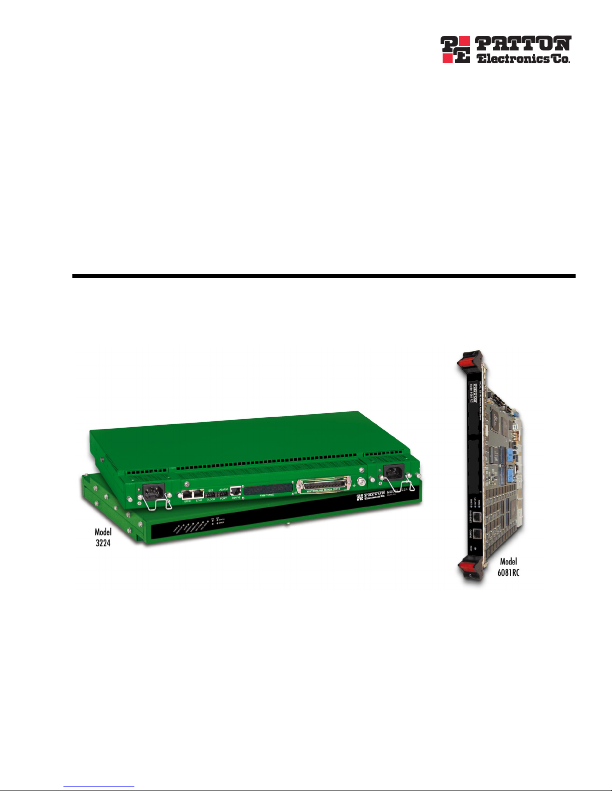
The Patton Model 3224 (see figure 1) and ForeFront
software platforms. The 3224 is a central site standalone device which connects and routes up to 24 G.SHDSL
subscribers directly. The Model 6081RC is installed in Patton’s ForeFront chassis system at a central site and
routes/bridges DSL subscribers data when used in conjunction with Patton’s model 3096RC( 16-port
G.SHDSL TDAC) and/or 3196RC (16-port iDSL T-DACS).
The Models 3224 IpDSLAM and 6081RC EdgeRoute Network Access Server powerful routing engines enable
network engineers to deploy flexible bridged or routed applications. Routed links can be configured using
Static, RIP (Routing Information Protocol), or OSPF (Open Shortest Path First) protocols. This guide
addresses configuration steps needed for bridged data and routed applications.
Model
6081RC (see figure 2) share routing and bridging
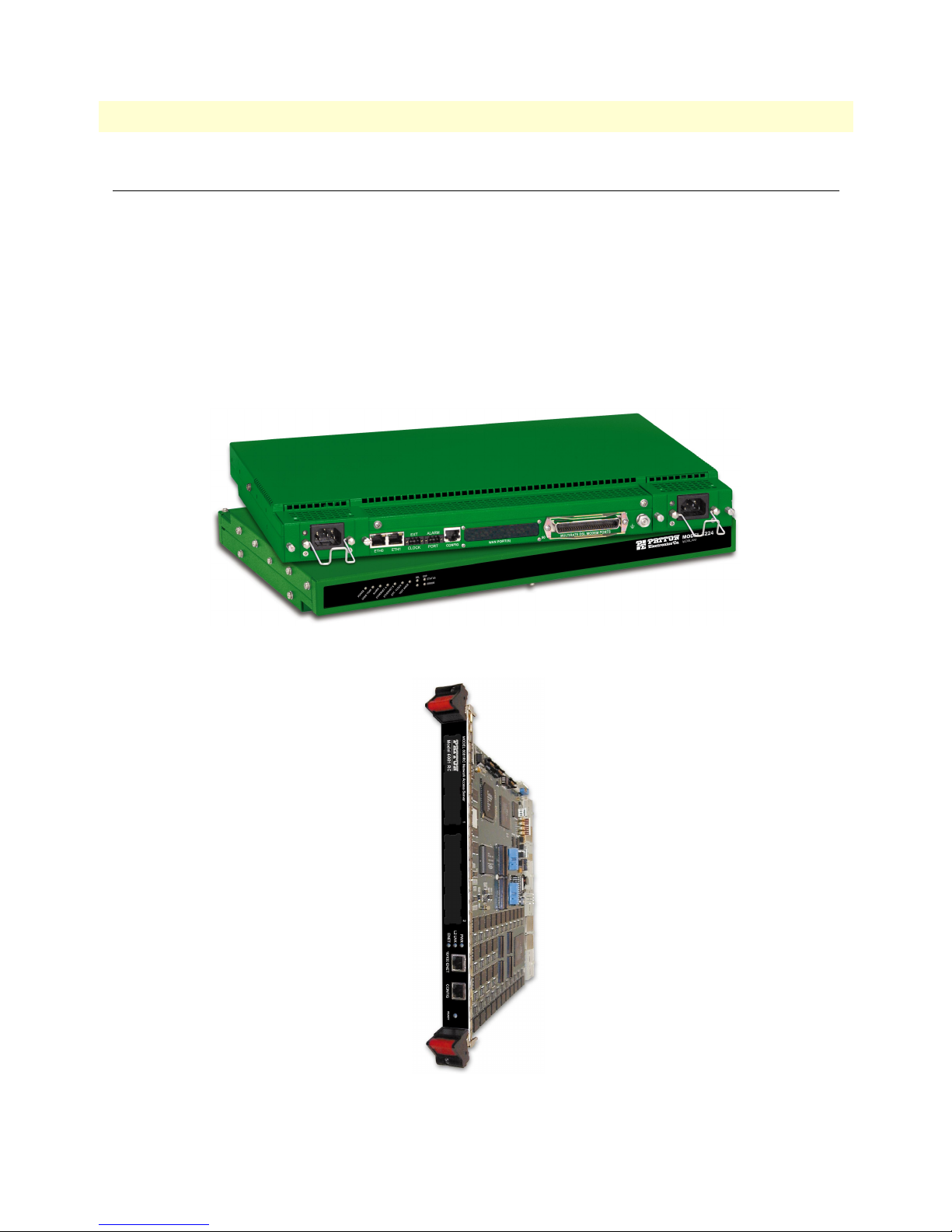
Figure 1. Model 3224 IpDSLAM (
Forest Green
version shown)
Figure 2. Model 6081RC
Overview
Page 9
7
Models 3224 G.SHDSL IpDSLAM & 6081RC NAS Applications Guide
1 • Introduction
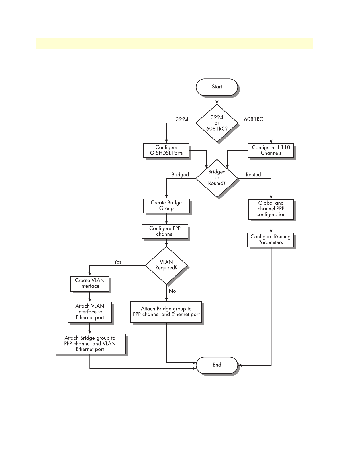
Figure 3 shows the factors that should be considered when configuring bridged or routed operation.
Figure 3. Bridged and routed configuration flow chart
Overview
Page 10

8
1 • Introduction
Models 3224 G.SHDSL IpDSLAM & 6081RC NAS Applications Guide
Overview
Page 11

Chapter 2
Chapter contents
Introduction..........................................................................................................................................................10
Physical layer characteristics...................................................................................................................................10
Configuring Model 3224 G.SHDSL parameters ...................................................................................................11
Configuring Model 6081RC H.110 parameters ....................................................................................................12
Defining H.110 channels ................................................................................................................................13
Defining H.110 ports, timeslots, and direction ...............................................................................................13
Physical layer configuration
9
Page 12

10
2 • Physical layer configuration
Models 3224 G.SHDSL IpDSLAM & 6081RC NAS Applications Guide
Introduction
The Models 3224 and 6081RC share routing and bridging software platforms, and both are central
site devices.
The 3224 is equipped with 24 G.SHDSL ports running at speeds from 192kbps to 4.6Mbps. The G.SHDSL
ports connect to customer premise G.SHDSL modem/routers such as the Patton Model 3201.
The Model 6081RC is mounted on a Patton Electronics ForeFront chassis (Models 6276, 6476, or 6676). The
6081RC connects to ForeFront function cards such as the 3096RC, 3196RC, 2616RC, or 6511RC via a midplane H.110 bus. In G.SHDSL applications, DSL frames carrying data from customer sites are terminated at
the ForeFront chassis by a Model 3096RC; data is then passed to the model 6081RC via H.110 ports.
Physical layer characteristics
The Model 3224 has 24 G.SHDSL ports structured in nx64kbps timeslots from 192kbps to 4.6Mbps, and
two 10/100base-T Ethernet ports.
The Model 6081RC has 32 H.110 ports (each port structured in 128 unidirectional 64kbps slots), and three
10/100base-T Ethernet ports.
This chapter contains the following sections that describe configuring the Model 3224 G.SHDSL ports and
Model 6081RC H.110 ports:
• “Configuring Model 3224 G.SHDSL parameters” on page 11
• “Configuring Model 6081RC H.110 parameters” on page 12
Introduction
Page 13
11
1.
2.
Models 3224 G.SHDSL IpDSLAM & 6081RC NAS Applications Guide
Figure 4. 3224 Web Management home page
2 • Physical layer configuration
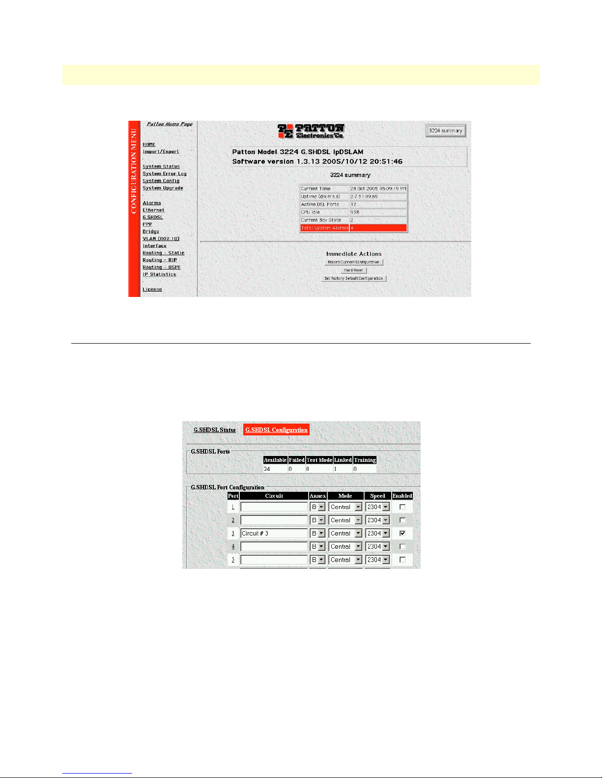
Configuring Model 3224 G.SHDSL parameters
To modify the values of the G.SHDSL configurable parameters, do the following:
On the left side of the web management home page, in the configuration menu pane, click the G.SHDSL
-> G.SHDSL Configuration hyperlink. The G.SHDSL status and configuration pages (see figure 5) will
appear on your screen.
Figure 5. G.SHDSL Configuration page
Use the drop-down menus to select your desired values for the annex and/or speed parameters for each
G.SHDSL port (enter configuration for port 3).
– Circuit # - Use alphanumeric characters to enter a circuit description.
– Annex – Select Annex B for this application
– Mode – Select Central mode of operation
– Speed – Select required speeds for this port.
Configuring Model 3224 G.SHDSL parameters
Page 14
12
–
3.
2 • Physical layer configuration
Models 3224 G.SHDSL IpDSLAM & 6081RC NAS Applications Guide
Enabled – Click on the check box to enable this port (port 3)
If you wish to disable any G.SHDSL ports that you don’t intend to use, click the
Enable check-box corre-
sponding to the ports you wish to disable in order to remove the check-mark and disable that port.
4. Scroll to the bottom of the page and click the Submit button to implement and save your changes. This
completes the instructions for configuring Ethernet bridging applications.
Configuring Model 6081RC H.110 parameters
The Model 6081RC card routes/bridges data from H.110 and Ethernet ports. The 6081RC connect to the
ForeFront chassis H.110 bus via mating mid-plane connectors.
There are 32 H.110 ports available on the ForeFront chassis H.110 bus, Each of the function cards (i.e.,
6081RC, 3096RC, 6511RC, etc.) have access to all 32 ports on the bus.
Characteristics of the H.110 bus:
• The H.110 bus is partitioned into 32 ports.
• Each H.110 port can handle up to 128 timeslots, each timeslot is 64 kbps.
• H.110 timeslots are unidirectional, for a full duplex link timeslots need to be defined for each direction of
transmission.
• H.110 port numbers between two cards must match.
• Direction of transmission between two cards must complement each other.
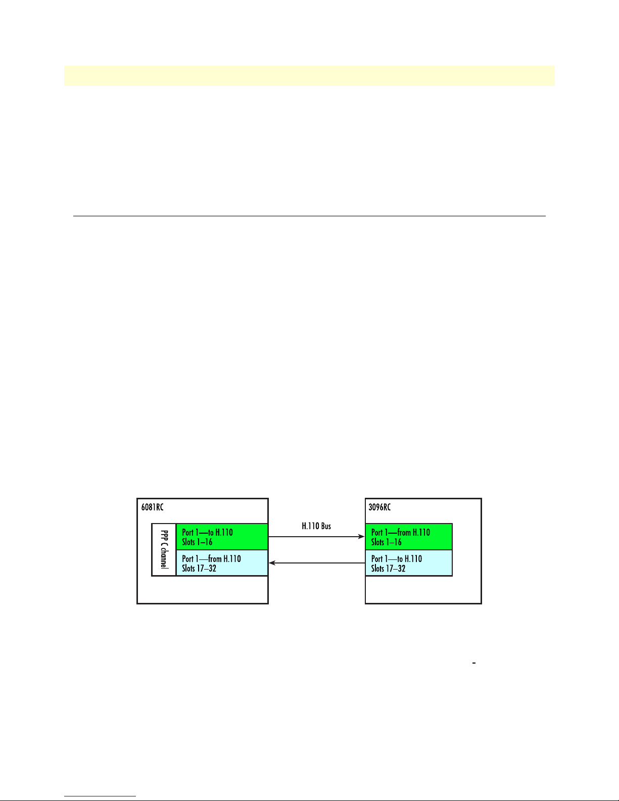
Figure 6 shows an H.110 bus interconnection connection between a 6081RC and a 3096RC. Two maps are
necessary for a full duplex link; both maps must have the same number of timeslots in each direction. In addition, the 6081RC H.110 port should connect to a corresponding 3096RC H.110 port. Similarly, the H.110
directions between the 6081RC and the 3096RC maps should complement each other, for example timeslots
in a “to H.110” port on the 6081RC, should go to timeslots in a “from H.110” port on the 3096RC.
Figure 6. H.110 port correspondence and direction
Defining H.110 channels
From the standpoint of the 6081RC, H.110 ports and timeslot are assigned to PPP channels. To configure
H.110 channels, do the following:
1. Click on the H.110 link in the Configuration Menu pane (see figure 4 on page 11) to display the
Channel Configuration page (see figure 7).
H.110
Configuring Model 6081RC H.110 parameters
Page 15

Models 3224 G.SHDSL IpDSLAM & 6081RC NAS Applications Guide 2 • Physical layer configuration
Figure 7. H110 Channel Configuration page
2. Type a description for the channel (in figure 7, the description would be Location1). This description will
be associated with a PPP channel defined later in this procedure).
3. Click on the
Add Channel button to create the new channel.
Figure 8. H.110 Channel Configuration window
4. Click on the channel number hyperlink in the Channel column (in figure 8, you would click on
channel 1) to refresh the page and cause information about the newly created channel to appear. Channels
will be numbered (starting with 1) in the order they are entered.
Note If you want to delete a channel configuration from the listing, click
the
Delete check box for the channel you want removed, then click
the Delete Channel(s) button.
Note If a bridged or routed PPP link is active on this channel, deactivate
the PPP link before deleting the H.110 channel.
Defining H.110 ports, timeslots, and direction
1. Click on the channel number hyperlink in the H.110 Channel Configuration page to go to the H.110 Set-
tings channel timeslot mapping page (see figure 9). The page displays the channel number, description,
and places to add a timeslot map. This page provides several buttons for navigating through stored bridge
configuration:
– The Refresh Page button forces the 6081RC to display changes made since the previous refresh cycle
– The First Channel button displays the configuration for the first channel in the H110 Channel Config-
uration page listing of channels (see figure 9).
Configuring Model 6081RC H.110 parameters 13
Page 16

2 • Physical layer configuration Models 3224 G.SHDSL IpDSLAM & 6081RC NAS Applications Guide
Figure 9. Channel timeslot mapping page
– The Previous Channel button displays the configuration for the channel previous to the one
currently displayed
– The Next Channel button displays the configuration for the channel following the one
currently displayed
– The Last Channel button displays the configuration for the last channel in the H110 Channel Configu-
ration page listing of channel (see figure 9 on page 14).
– The Reset button cancels changes made to a channel configuration.
– The Submit button saves changes made to a channel configuration.
Enter configuration parameters for a channel as follows:
1. Enter a port number (H.110 bus port numbers range from 1 to 32) in the
2. Enter the
Starting Timeslot—each H.110 port can handle up to 128 slots (for example, if timeslots 1–16
Port text box.
will be used, enter 1 in this text box).
3. Enter the length of the channel in number of timeslots (for example, if the range of timeslots is from 1–16,
enter 16 timeslots in this text box).
4. Select to H.110 from the
Direction pop-up menu. Each link in the H.110 bus should be duplex, define the
direction of transmission “to H.110” or “from H.110”.
5. Click the Add Map button to enter the H.110 map. This will be the map that will connect port 1 in the
6081RC to the “From H.110” direction.
6. Enter 1 in the
Port text box (port 1).
Note Any other available port (from 1-32) could be selected as long as it
matches a 3096RC port.
7. Enter the
8. Enter the length in number of timeslots in the
Starting Timeslot—for example if using timeslots 17–32, enters 17 in this text box).
Length text box.
9. Select To H.110 from the
Direction pop-up menu.
10. Click the Add Map button to save changes.
14 Configuring Model 6081RC H.110 parameters
Page 17

Models 3224 G.SHDSL IpDSLAM & 6081RC NAS Applications Guide 2 • Physical layer configuration
Note If you want to delete a map configuration from the listing, click the
Delete check box for the map you want removed, then click the
Delete Map(s) button.
Once both maps for a channel have been entered, the
tion as shown in figure 10.
Figure 10. H.110 Settings page showing map information for new channel
H.110 Settings page will display the map informa-
Configuring Model 6081RC H.110 parameters 15
Page 18

2 • Physical layer configuration Models 3224 G.SHDSL IpDSLAM & 6081RC NAS Applications Guide
16 Configuring Model 6081RC H.110 parameters
Page 19

Chapter 3 Bridged data application
Chapter contents
Introduction..........................................................................................................................................................18
Basic assumptions..................................................................................................................................................20
Defaults.................................................................................................................................................................21
CPE configuration.................................................................................................................................................22
Initiating bridged Ethernet data communications..................................................................................................22
Modifying the factory default configuration ..........................................................................................................22
Logging in using the factory-default IP address ...............................................................................................23
Modifying the IP address for Ethernet interface A (optional) ..........................................................................25
Creating a bridge group.........................................................................................................................................26
PPP channel configuration ....................................................................................................................................28
Interface configuration ..........................................................................................................................................31
Alternate Interface Configuration for Model 6081RC .....................................................................................32
Verifying operation................................................................................................................................................33
Verifying bridged connection ..........................................................................................................................33
17
Page 20

3 • Bridged data application Models 3224 G.SHDSL IpDSLAM & 6081RC NAS Applications Guide
Introduction
In bridged Ethernet applications, the IpDSLAM, and EdgeRoute Network Access Server incorporated in Patton ForeFront system, function as an Ethernet hub for interconnecting G.SHDSL access lines and an Ethernet
LAN. Functioning as a hub, they deliver data traffic to and from all interfaces (Subscriber ports and one Ethernet LAN interface) by means of Ethernet bridging at the data link layer—layer 2 of the Open Systems Interconnection (OSI) model. The IpDSLAM and EdgeRoute Network Access Server use bridging control protocol
(BCP) to provide the bridging function. The IpDSLAM and EdgeRoute Network Access Server use point-topoint protocol (PPP) for data delivery across the G.SHDSL links, by encapsulating each BCP datagram in a
PPP frame.
Figure 11. Model 3324 bridged data application diagram
In general, network engineers may find the Ethernet bridging configuration useful for any data communication system requiring long-range connections between remote devices and an Ethernet LAN at a central location. (See figure 11 for Model 3224 bridged data application diagram and figure 12 on page 19 for the Model
6081RC diagram.) As a more specific example, a bridged Ethernet solution may be used when implementing
such a real-world application as Internet Service for small and home based businesses. In such a scenario, mini
LANs supporting from 1 to 50 users would be connected via a G.SHDSL line to the IpDSLAM, and EdgeRoute Network Access Server (using 3096RC cards), which would then provide bridged communications with
servers and Internet gateways connected to the main LAN.
18 Introduction
Page 21

Models 3224 G.SHDSL IpDSLAM & 6081RC NAS Applications Guide 3 • Bridged data application
Figure 12. Model 6081RC bridged data application diagram
Introduction 19
Page 22

3 • Bridged data application Models 3224 G.SHDSL IpDSLAM & 6081RC NAS Applications Guide
Basic assumptions
The bridged Ethernet network is based on the following basic assumptions:
• Ethernet Interface A (Rear panel 3224, front panel 6081RC)
- You will connect a management workstation (such as a PC) to the IpDSLAM or EdgeRoute Network
Access Server Ethernet Interface A.
- You will use the management workstation on Interface A to configure the IpDSLAM or EdgeRoute Net-
work Access Server using a web browser.
Figure 13. Port connectors
Note Your workstation must reside within the same IP subnetwork as
Ethernet Interface A in order to connect to the IpDSLAM or EdgeRoute Network Access Server management interface via the factorydefault IP address, which is 198.168.200.98. In other words, the first
three octets of your workstation’s IP address must be 198.168.200.
20 Basic assumptions
Page 23

Models 3224 G.SHDSL IpDSLAM & 6081RC NAS Applications Guide 3 • Bridged data application
Note Once the IpDSLAM or EdgeRoute Network Access Server have been
configured for operation, you may wish to connect Ethernet Port A to
the LAN. Doing so offers the following advantages:
• Remote management—you can log in to the IpDSLAM and Edg-
eRoute Network Access Server management interface remotely using
any workstation connected to the LAN and standard http browser.
• Multiple operators—two or more operators can manage the IpD-
SLAM and EdgeRoute Network Access Server, at the same time or
at different times, using multiple workstations on the LAN.
Before moving Ethernet Port A to the LAN, you must first assign an
IP address to Ethernet Port A that has the same network number as
the LAN. For further instructions, see section“Modifying the IP
address for Ethernet interface A (optional)” on page 24.
• Ethernet Interface B (front Panel, Model 3224, front panel PMC module 6081RC)
- You will connect the IpDSLAM or EdgeRoute Network Access Server Ethernet Port B to an
Ethernet LAN.
Note This procedure assumes that the Model 6081RC is equipped with a
PMC card which presents Ethernet port B on the front panel of the
unit. Units not equipped with a PMC card have both Ethernet ports
B and C internally connected to the ForeFront Chassis midplane.
It’s possible to use the model 6081RC Ethernet port A simultaneously for bridging and management (see section “Alternate Inter-
face Configuration for Model 6081RC” on page 31 for details.)
- All traffic on Ethernet Port B will be delivered via Ethernet bridging at layer 2 of the OSI model.
- No IP address will be needed by or assigned to Ethernet Port B.
Defaults
The bridged Ethernet configuration described in section “Basic assumptions” operates using the 3224 default
values. For the Model 6081RC, the operator must configure H.110 port parameters and create PPP transport
and bridge groups.
• Ethernet Interface A—By factory default the IP address assigned to Ethernet interface A for both model
3224 and 6081RC is 192.168.200.98/24 ( the designation /24 indicates the IP address has a netmask of
255.255.255.0)
• Ethernet Interface B—By factory default Ethernet interface B for both 3224 and 6081RC is not assigned
an IP address. In bridged data application, because this Ethernet interface is intended to handle bridged
traffic only, no IP address is needed
• Ethernet Interface C (6081RC only)—By factory default Ethernet interface C in the 6081RC is not
assigned an IP address. This Ethernet interface is not used in this particular application
Transport Defaults 3224:
Defaults 21
Page 24

3 • Bridged data application Models 3224 G.SHDSL IpDSLAM & 6081RC NAS Applications Guide
• 3224 G.SHDSL ports 1-24—All 24 G.SHDSL ports are factory configured with the following defaults:
- PPP Mode = BCP (bridging control protocol)
- G.SHDSL Annex = B—Annex B is typically used in most countries, while Annex A is used in
North America
- G.SHDSL speed = 2.034—This setting corresponds to a speed of 2.304 Mbps
- Enable = checked—This value enables the Ethernet bridging function on the port
Transport Defaults 6081RC:
• 6081RC H.110 ports 1-32 - Factory default un-configured – operator must define H.110 ports and PPP
channels.
- PPP Mode (BCP, IPCP) = un-configured—Operator must define PPP/H.110 channels.
- Bridge group = un-configured—Operator must first define bridge group, and then attach all ports (Ether-
net, H.110) for bridging.
- H.110 ports = un-configured
- H.110 port speed = un-configured
- Defined
CPE configuration
The Patton Model 3201 Router Modems used in the Bridged Ethernet network described above must be factory-configured in CP mode (as opposed to CO mode). If any Model 3201 used in this network is factory-configured in CO mode, you must re-configure the device for CP mode. For more information on configuring the
Model 3201, refer to the Model 3201 Getting Started Guide or Administrator’s Reference Guide that shipped
with the device.
Initiating bridged Ethernet data communications
Once you have made the connections shown in figure 1 on page 3, you need only power up the IpDSLAM and
the connected Model 3201 CPE devices for the bridged Ethernet network to begin operation and start carrying data traffic. The rest of this section describes the procedures for modifying the IpDSLAM’s factory default
configuration for bridged data application.
Modifying the factory default configuration
Modifying the IpDSLAM’s factory-default configuration comprises the following major tasks:
• Modifying the IP Address for Ethernet Interface A (if desired) (see section “Modifying the IP address for
Ethernet interface A (optional)” on page 24)
• Configuring the G.SHDSL port(s) (Model 3224) (see section “Configuring Model 3224 G.SHDSL param-
eters” on page 11)
• Configuring H.110 parameters (Model 6081RC) (see section “Configuring Model 6081RC H.110 param-
eters” on page 12)
• Creating a bridge group (see section “Creating a bridge group” on page 25)
22 CPE configuration
Page 25

Models 3224 G.SHDSL IpDSLAM & 6081RC NAS Applications Guide 3 • Bridged data application
• Configuring the PPP/BCP channel (see section “PPP channel configuration” on page 27)
• Testing bridged data operation (see section “Verifying operation” on page 32)
Logging in using the factory-default IP address
Your workstation must reside within the same IP subnetwork as Ethernet Interface A in order to connect to the
IpDSLAMs management interface via the factory-default IP address, which is 198.168.200.98. That is, the
first three octets or your workstation’s IP address must be 198.168.200. Using a workstation connected to the
IpDSLAM’s Ethernet Interface A, do the following:
1. Power up the workstation and open a standard HTTP browser (such as Microsoft Internet Explorer or
Netscape Navigator).
2. In your browser’s address field, enter 192.168.200.98 (the default IP address for the IpDSLAM’s Ethernet
Interface A), then press the <enter> key. The login popup window (see figure 14) will appear on your
screen.
Figure 14. Logging window
3. In the login popup window, enter superuser for user name and superuser for password, then click the OK
button. The IpDSLAM’s Web management home page (see figure 15) displays.
Figure 15. 3224 Web Management home page
Modifying the factory default configuration 23
Page 26

3 • Bridged data application Models 3224 G.SHDSL IpDSLAM & 6081RC NAS Applications Guide
Figure 16. 6081RC Web Management home page
Modifying the IP address for Ethernet interface A (optional)
You may wish to connect Ethernet Port A to the LAN in order to enable remote management and multiple
operator capabilities described below:
• Remote management—You can log in to Ethernet port A remotely using any workstation connected to the
LAN and standard HTTP browser.
• Multiple operators—Two or more operators can manage the Model 3224 or Model 6081RC, at the same
time or at different times, using multiple workstations on the LAN.
Before connecting Ethernet Port A to the LAN, you must first assign an IP address to Ethernet Port A that has
the same network number as the LAN. To modify the IP address, do the following:
1. On the menu pane at the left side of the web management home page (see figure 15), click the Interface
hyperlink. The
Interface Configuration window will appear (see figure 17).
Figure 17. Interface configuration window
2. Use the drop down menu to select Ethernet A. Enter the new IP address for Ethernet A in the IP Address
field for Interface A. The new IP address must have the same network number as the Ethernet LAN to
which you intend to connect Interface A.
3. In the
NetMask field for Interface A, enter the netmask for the new IP address you have chosen.
24 Modifying the factory default configuration
Page 27

Models 3224 G.SHDSL IpDSLAM & 6081RC NAS Applications Guide 3 • Bridged data application
Figure 18. Interface configuration window
4. In the Interface Configuration table, place a checkmark in the box next to Ethernet A (see figure 18).
5. Click the
Submit button (see figure 18).
6. To save the new values, click the configure button corresponding to Interface A (to the right of the Net-
Mask field).
Note After re-defining the IP address for Ethernet Interface A for connec-
tion to an Ethernet LAN, your workstation will lose connection to
the Ethernet port A. Disconnect your workstation and connect Interface A to the Ethernet LAN, you can then log in to the management
interface from a workstation connected to the LAN using a web
browser and the new IP address just assigned to Interface A.
Creating a bridge group
In order for the 3224 or the 6081RC to bridge data from and to several ports is necessary to create a
bridge group.
Do the following to configure bridge groups:
1. Click the Bridge link in the
uration page (see figure 11).
Configuration Menu pane (see figure 3 on page 6) to display the Bridge Config-
2. Type the name of the bridge group (Site 1 in the example shown in figure 19) to create a new bridge that
will link DSL or H.110 ports and Ethernet port B.
Creating a bridge group 25
Figure 19. Bridge Configuration page
Page 28

3 • Bridged data application Models 3224 G.SHDSL IpDSLAM & 6081RC NAS Applications Guide
Figure 20. Bridge Configuration window showing new bridge
3. Click the Add Bridge button (see figure 19), to display the new bridge as shown in figure 20.
Note If you want to delete a bridge configuration from the listing, click the
Delete check box for the bridge you want removed, then click the
Delete Bridge(s) button.
4. Now that the bridge group has been created, click on Bridge 1 group ID hyperlink, this action will take
you to the
Bridge 1 Configuration page (see figure 21). This page provides several buttons for navigating
through stored bridge configuration:
– The Refresh Page button forces the 3224 or 6081RC to display changes made since the previous
refresh cycle
– The First Bridge button displays the configuration for the first bridge in the
listing of bridges (see figure 19 on page 25).
– The Previous Bridge button displays the configuration for the bridge previous to the one
currently displayed
– The Next Bridge button displays the configuration for the bridge following the one currently displayed
– The Last Bridge button displays the configuration for the last bridge in the
listing of bridges (see figure 19 on page 25)
– The Reset button cancels changes made to a bridge configuration.
26 Creating a bridge group
Figure 21. Bridge Configuration Options
Bridge Configuration page
Bridge Configuration page
Page 29

Models 3224 G.SHDSL IpDSLAM & 6081RC NAS Applications Guide 3 • Bridged data application
– The Submit button saves changes made to a bridge configuration.
5. Type a short description for Bridge 1 in the
Description text box.
6. Aging time is the number of seconds a MAC-address will be held in the forwarding database after receiving
a packet from this MAC address. The entries in the forwarding database are periodically timed out to
ensure they won’t stay around forever. If desired, type a value (in seconds) for the forwarding table aging
time in the
Aging Time box. The default value for this setting is 300 seconds (5 minutes).
7. The 3224 and 6081RC periodically check the forwarding database for timed-out entries which are then
deleted. The
Garbage Collection Interval is the time (in seconds) that between each checks of the forward-
ing database.
8. Spanning tree is a link management protocol that provides path redundancy while preventing undesirable
loops in the network. For a Layer 2 Ethernet or Token Ring network to function properly, only one active
path must exist between two stations. Spanning-tree operation is transparent to end stations, which cannot
detect whether they are connected to a single LAN segment or a switched LAN of multiple segments.
If you will not be enabling Spanning Tree options, go to step 9. Otherwise, click the
Enable Spanning Tree
box to activate Spanning Tree Options. The following options are available for configuration:
– Priority: The switch with the highest bridge priority (the lowest numerical priority value) is elected as
the spanning-tree root switch, which is the logical center of the spanning-tree topology in a switched
network. If all switches are configured with the default priority (32768), the switch with the lowest
MAC address in the Layer 2 network becomes the root switch. Under some circumstances, traffic patterns may require that a different switch be assigned as the root switch than that which was chosen by
default. Increasing the priority by typing a number in the Priority box that is less than the default 32768
value forces the switch to become the root switch.
– Forward Delay: This value is the time a port will remain in the listening and learning states before enter-
ing the forwarding state.
– Hello Time: The amount of time a port will remain in the listening and learning states before entering
the forwarding state.
– Max Message Age: The length of time the switch will store protocol information received on a port.
9. Once all options have been entered, click the Submit button to save changes.
PPP channel configuration
The Models 3224 and 6081RC generate PPP channels to transport bridged (BCP) or routed (IPCP) data to
and from subscriber’s premises.
In the case of the Model 3224, PPP channels are created automatically and each channel is assigned to a
G.SHDSL port. For example PPP channel 1 is assigned to G.SHDSL port 1, PPP channel 2 is assigned to
G.SHDSL port 2, etc.
In the case of the 6081RC, a PPP channel is generated automatically only when the operator creates a H.110
channel. When an H.110 channel is created, it automatically receives a sequential ID number starting at 1.
Consequently, the corresponding PPP channel is also assigned the same ID number. For example, PPP Channel 3 is attached to H.110 channel 3.
PPP channel configuration 27
Page 30

3 • Bridged data application Models 3224 G.SHDSL IpDSLAM & 6081RC NAS Applications Guide
Additionally, if a PPP channel is to transport bridged data a BCP interface is created (see section “Interface
configuration” on page 30), the BCP interface also takes the PPP channel number, for example BCP3 interface
corresponds to PPP channel 3, which in turn is attached to H.110 channel 3 (6081RC) or to the G.SHDSL
port 3. The same is true for routed connections (IPCP).
Figure 22. Model 3224 bridged PPP channel and interfaces
Figure 23. Model 6081RC bridged PPP channel and interfaces
The PPP channel configuration page allows assignment of bridged or routed sessions to DSL or H.110 ports,
as well as definition of PPP link parameters such as MRU, retry times, authentication, etc.
1. The PPP page displays PPP channel status information, in addition it offer links for global, multilink, and
radius configuration pages.
There are two ways to access a PPP channel configuration page: by clicking on the channel number in the
status window, and the other way is by clicking on the Configuration option at the top of the main PPP
page. In this application, we will access the PPP channel configuration page by clicking on the channel
number in the status window.
Click on the PPP link in the
Configuration Menu pane (see figure 15 on page 23) to display the PPP Con-
figuration page (see figure 24).
Figure 24. PPP Configuration page
2. Click on one of the hyperlinks in the Channel column to display the PPP Options page for the selected chan-
nel. The
PPP Channel Options page allows the operator to configure BCP or IPCP options for the channel.
This page also provides several buttons for navigating through all PPP channels.
– The Refresh Page button forces the 3224 or 6081RC to display changes made since the previous
refresh cycle
28 PPP channel configuration
Page 31

Models 3224 G.SHDSL IpDSLAM & 6081RC NAS Applications Guide 3 • Bridged data application
– The First Port button displays the configuration for the first port in the H.110 Channel Configuration
page listing of channels (see figure 24).
– The Previous Port button displays the configuration for the port previous to the one currently displayed
– The Next Port button displays the configuration for the port following the one currently displayed
– The Last Port button displays the configuration for the last port in the
page listing of channels (see figure 24)
– The Reset button cancels changes made to a port configuration.
– The Submit button saves changes made to a port configuration.
H.110 Channel Configuration
3. Under the heading PPP Options, select one of the following network-control protocols (NCP) from the
Mode menu:
– BCP (bridge control protocol)
– IPCP (Internet protocol control protocol)
Note Since this section is about configuring for bridged PPP, you would
select the BCP option.
4. Click on the Enable button below the
5. Click on the Passive checkbox if you want the particular PPP channel to wait for the remote PPP device
linked to this channel to initiate PPP channel negotiation. If box is unchecked, this PPP channel will initiate negotiation to establish a PPP session with remote device. Normally this box should be checked.
6. Under
BCP Options, select the bridge group that the PPP channel will be attached to (for this example
select Bridge 1) and check the
PPP channel configuration 29
Figure 25. PPP Options page
Mode menu to enable the NCP.
Bridged box located just above the drop-down menu.
Page 32

3 • Bridged data application Models 3224 G.SHDSL IpDSLAM & 6081RC NAS Applications Guide
7. Configure LCP options as needed or accept the default settings. Do not configure IP and IPCP options.
8. Click on the Submit button to save changes.
9. Repeat the PPP channel configuration steps 1 through 7 for other channels as needed.
Once all parameters have been configured, the PPP Status page should display the information shown in
figure 26.
Figure 26. PPP Status page
At this point the 3224 or 6081RC will start negotiating PPP/BCP connections with a remote peer. The
Status window will turn yellow, indicating that negotiation is in progress.
10. Attach a defined bridge to an Ethernet port, so that traffic bridged from the remote CPEs is forwarded to
the LAN attached to the 3224 or 6081RC.
Note Bridge 1 can be attached to any physical interface including back-
plane Ethernet ports or other H.110 ports.
Interface configuration
The Interface Configuration page (see figure 27) displays all interfaces (physical and logical) previously defined.
In this example, PPP interface BCP 3 (channel 3) and corresponding bridge Bridge 1 - site1, Ethernet A, Ethernet B, and a Loopback interface (default) are shown.
Figure 27. Interface Configuration Page
To activate a bridged link from customer sites (BCP) between the remote CPEs and the 3224 or 6081RC
bridge, do the following:
30 Interface configuration
Page 33

Models 3224 G.SHDSL IpDSLAM & 6081RC NAS Applications Guide 3 • Bridged data application
1. Click the check boxes in the Enable column to add a check to the BCP 3 and Bridge entries in the Inter-
face column (see figure 27).
2. In the
BCP 3 row (see figure 27), use the drop down menu under the Bridge Group column to select the
Bridge 1 – Site 1 option. Under the
Bridged column, place a checkmark on the box corresponding to BCP3.
3. Click on the Submit button to save changes.
At this time, a PPP/BCP connection between the 3224 or 6081RC and the remote CPEs may have been established (check this by clicking on the PPP main menu option), each PPP connection will be displayed in color
code, the color green meaning that a connection has been established. However, there is not yet a connection
between the PPP/BCP modules and the Ethernet port (that is, the bridge module does not have a path to the
Ethernet port and therefore no bridged data can be sent to the LAN). To activate a connection between the
bridge module and the front panel Ethernet interface (Ethernet B), do the following:
1. In the
Ethernet B row (see figure 27 on page 30), click to add a checkmark on the box under the Enabled
column.
2. In the
Ethernet B row, locate the drop down menu under Bridge Group (see figure 27 on page 30), select
Bridge 1-Site1
3. Place a checkmark under the bridged column to enable bridged data to Ethernet B.
4. Click on the Submit button at the bottom of the screen.
Alternate Interface Configuration for Model 6081RC
If your Model 6081RC is not equipped with a PMC card presenting Ethernet port B on the front panel of the
unit, Ethernet port A can be simultaneously used for bridging and management.
To activate a connection between the bridge module and the front panel Ethernet interface (Ethernet A), do
the following:
1. In the
IP Address Configuration section of the Interface Configuration page (see figure 28), select Bridge 1
from the
Interface menu.
Figure 28. IP Address Configuration section of the Interface Configuration page
2. Type an IP address of 192.168.200.20 and a Netmask of 255.255.255.0 (this will be the new manage-
ment address for the 6081RC). Click on the
3. In the
Ethernet A row, under the Bridge Group column, select Bridge 1 – Location1&2 from the menu,
then click to add a checkmark to the box under the
Configure button.
Bridged column. This action attaches Ethernet Port A
to the bridge group.
4. In the BCP 3 row, use the drop down menu under the
option. Under the
5. Click the
Submit button to activate changes on this page.
Bridged column, place a checkmark in the box corresponding to BCP3.
Bridge Group column to select Bridge 1 – Site 1
Interface configuration 31
Page 34

3 • Bridged data application Models 3224 G.SHDSL IpDSLAM & 6081RC NAS Applications Guide
Note At this time, the 6081RC management web server can only be
accessed via Bridge 1 IP addresses 192.168.200.20. It may take a several minutes for the card to respond to management commands after
this change.
Verifying operation
Before any testing can be performed verify operation of the DSL, PPP, and bridging modules. To verify the
operation of the 3201 and 3224/6081RC in this application go to the 3224 configuration pages:
• To view the G.SHDSL ports on the Model 3224, click on the G.SHDSL link on the Configuration menu
pane. Verify that the DSL port 3 is up and linked to the remote unit.
Figure 29. G.SHDSL Status page
• Click on the PPP link and verify that the PPP channel 3 is up an running
Figure 30. PPP status page
Verifying bridged connection
To verify the bridged connection between the 3224/6081RC and the remote device (3201) use a PC or terminal at the customer site to ping a PC or terminal attached to the LAN port (Ethernet B) of the Model 3224
or 6081RC.
32 Verifying operation
Page 35

Models 3224 G.SHDSL IpDSLAM & 6081RC NAS Applications Guide 3 • Bridged data application
For example, if a PC or terminal at the remote site uses IP address 192.168.200.20, enter the following command at the PC attached to the model 3201: ping 192.168.200.20, the remote computer should respond with
a ping reply.
Figure 31. Testing the bridged connection
You can also use visual PPP connection on status pages at the 3224/6081.
Verifying operation 33
Page 36

3 • Bridged data application Models 3224 G.SHDSL IpDSLAM & 6081RC NAS Applications Guide
34 Verifying operation
Page 37

Chapter 4 VLAN bridged connection
Chapter contents
Introduction..........................................................................................................................................................36
Attaching a VLAN ID to an Ethernet interface......................................................................................................36
Attaching a bridge interface to a VLAN module ....................................................................................................37
35
Page 38

4 • VLAN bridged connection Models 3224 G.SHDSL IpDSLAM & 6081RC NAS Applications Guide
Introduction
The Models 3224 and 6081RC support vLAN (802.1Q) connections between remote users and a central location. To create a VLAN connection for bridged PPP connections, each PPP connection is attached to a bridge
connected to a separate virtual Ethernet interface. Finally, each virtual interface is attached to a physical Ethernet port as shown in figure 32).
Figure 32. VLAN connection diagram
Packets arriving from the remote CPE will be tagged with VLAN information and sent to the Ethernet port.
VLAN packets received from the LAN by the Ethernet port of the 3224 or 6081RC and corresponding to the
remote CPE, will be stripped of VLAN information and passed to the bridge module for transmission to the
remote CPE.
To create VLAN connections, do the following:
1. On the model 3224, Configure G.SHDSL Channels (see section “Configuring Model 3224 G.SHDSL
parameters” on page 11 for details). On the Model 6081RC, configure H.110 channels (see section “Con-
figuring Model 6081RC H.110 parameters” on page 12” for details)
2. Create a bridge group (see section “Creating a bridge group” on page 25).
3. Configure PPP channel parameters (see section “PPP channel configuration” on page 27).
4. Attach a VLAN ID to an Ethernet interface (see section “Attaching a VLAN ID to an Ethernet interface”
on page 36).
5. Attach the bridge/PPP to the VLAN module (see section “Attaching a bridge interface to a VLAN mod-
ule” on page 37).
Attaching a VLAN ID to an Ethernet interface
Once a bridge group and PPP channel has been configured, do the following:
1. Click the VLAN(8021Q) link in the
VLAN (802.1Q) Configuration page (see figure 33).
Figure 33. VLAN (802.1Q) Configuration page
Configuration Menu pane (see figure 3 on page 6) to display the
36 Introduction
Page 39

Models 3224 G.SHDSL IpDSLAM & 6081RC NAS Applications Guide 4 • VLAN bridged connection
2. In the Add VLAN section (see figure 33 on page 36), select the interface that will process VLAN packets
from the
Parent Interface menu.
3. In the
VLAN ID text box, type the desired number for this VLAN (up to 4096 with no reserved VLAN
numbers).
4. Click the Add VLAN button. Configured VLANs are displayed as shown in figure 34.
Figure 34. Configured VLAN Interfaces section of VLAN (802.1Q) Configuration page
Attaching a bridge interface to a VLAN module
Once the desired VLAN has been created, it is necessary to attach it to a bridge group as follows:
1. Click the Interface link in the
page (see figure 35).
Configuration Menu pane (see figure 3 on page 6) to display the Interface
Figure 35. Interface page
2. Locate the Ethernet port that has the VLAN ID created in section “Attaching a VLAN ID to an Ethernet
interface” on page 36 and click to place a checkmark on the box in the
bridge group from the menu in
Bridge Group column (this bridge group should correspond to the remote
CPE for which a VLAN is required), then click to place a checkmark on the box in the
3. Click the
Submit button at the bottom of the screen.
Enabled column. Select the desired
Bridged column.
Attaching a bridge interface to a VLAN module 37
Page 40

4 • VLAN bridged connection Models 3224 G.SHDSL IpDSLAM & 6081RC NAS Applications Guide
38 Attaching a bridge interface to a VLAN module
Page 41

Chapter 5 Routed application using RIP
Chapter contents
Introduction..........................................................................................................................................................40
Network diagram...................................................................................................................................................40
3224/6081RC configuration .................................................................................................................................40
Ethernet port A IP address configuration ........................................................................................................41
Configuring G.SHDSL parameters (3224 only) ..............................................................................................41
Configuring H.110 ports (6081RC only) .......................................................................................................41
PPP global and channel configuration .............................................................................................................41
Global configuration .................................................................................................................................41
PPP channel configuration ........................................................................................................................43
PPP options ....................................................................................................................................................43
LCP options ....................................................................................................................................................43
Multilink options ............................................................................................................................................44
IP options .......................................................................................................................................................44
IPCP options ..................................................................................................................................................44
RIP configuration ...........................................................................................................................................45
General options configuration .........................................................................................................................45
General .....................................................................................................................................................45
RIP timers .................................................................................................................................................46
39
Page 42

5 • Routed application using RIP Models 3224 G.SHDSL IpDSLAM & 6081RC NAS Applications Guide
Introduction
The 3224 and 6081RC include powerful routing engines which enable network engineers to implement flexible bridged or routed applications. Routed links can be configured using Static, RIP (Routing Information
Protocol), or OSPF (Open Shortest Path First) protocols. This applications document addresses configuration
steps needed for routed links using RIP.
Network diagram
The RIP Application can be implemented using either a Model 3224 or 6081RC, at a central location (Central
Office or ISP location), while remote locations use Patton’s Model 3201.
Up to 24 remote sites can be connected via DSL lines when using the Model 3224, and up to 128 customer
connections are possible using one 6081RC in combination with 3096RC cards. For the purpose of this application it is assumed that the 3224 or 6081RC reside in a different network than the 3201s at remote locations.
Customer data at remote locations is routed by the corresponding 3201 and sent via the DSL link to the central location. The central site model 3224/6081RC routes received data from incoming DSL (3224) or H.110
ports (6081RC) and route to Ethernet port A (IP address 192.168.200.98). Remote users reaching the central
LAN via DSL links can now access e-mail servers, web hosting servers, or an Internet gateway.
3224/6081RC configuration
Configuring the 3224 or 6081RC for this application includes the following steps:
1. Ethernet port A IP address configuration (see section “Ethernet port A IP address configuration” on
page 41)
2. Configuring G.SHDSL Parameters (3224 only) see section “Configuring G.SHDSL parameters (3224
only)” on page 41)
3. Configuring H.110 ports (6081RC only) see section “Configuring H.110 ports (6081RC only)” on
page 41)
4. Configure PPP global and channel configuration (see section “PPP global and channel configuration” on
page 41)
5. Configure RIP (see section “RIP configuration” on page 45)
6. Testing the link (see chapter 7, “Verifying operation” on page 53)
40 Introduction
Figure 36. Routed connection diagram
Page 43

Models 3224 G.SHDSL IpDSLAM & 6081RC NAS Applications Guide 5 • Routed application using RIP
Ethernet port A IP address configuration
Follow the Model 3224 Installation Guide or Model 6081RC Installation Guide to change IP address (if needed)
via CLI or use the web browser as follows:
1. Click on the Interface link in the
play the
Interface Configuration page (see figure 20).
Configuration Menu pane (see figure 15 or figure 16 on page 24) to dis-
2. At the interface configuration page, use the drop down menu and select Ethernet A. Enter the new IP
address and corresponding netmask, and click on the Configure button.
Figure 37. Ethernet A configuration window
Configuring G.SHDSL parameters (3224 only)
See section “Configuring Model 3224 G.SHDSL parameters” on page 11.
Configuring H.110 ports (6081RC only)
See section “Configuring Model 6081RC H.110 parameters” on page 12.
PPP
global and channel
configuration
The Model 3224 and 6081RC PPP Configuration page is accessed from the main menu. Click on the PPP link
in the
Configuration Menu pane to reach the PPP page (see figure 38).
The PPP status window provides at-a-glance view of PPP channel/transport status, as well as links to Global,
Configuration, Multilink, Channel, and G.SHDSL (3224) or H.110 (6081RC) configuration pages.
Global configuration
Before configuring a PPP channel, it is necessary to create a pool of IP addresses. Addresses from this pool will
be later assigned automatically or manually by the user, to the local and remote PPP links (these are WAN IP
addresses for the PPP interfaces at each end of the link).
3224/6081RC configuration 41
Figure 38. PPP status and configuration page
Page 44

5 • Routed application using RIP Models 3224 G.SHDSL IpDSLAM & 6081RC NAS Applications Guide
To enter an IP address pool do the following:
1. Click on the Global link at the top of the page.
2. Enter the IP address pool information in
IP Options, IP Address Pool window,
3. Use IP Address 192.168.254 in this example. The 3224/6081RC will grab two consecutive addresses
beginning at 192.168.254.0 from this pool for each PPP channel connection, one for the local PPP interface and one for the remote PPP interface.
4. Leave all other settings for PPP, BCP, LCP and IPCP in this page in their default states.
5. Click on the Submit button.
Figure 39. PPP Global Configuration Page
The PPP configuration page matches PPP channels to G.SHDSL transports (ports) or H.110 ports; the Model
3224 assigns only one PPP channel per DSL connection (transport). For instance PPP Channel 1 will correspond to G.SHDSL port 1.
42 3224/6081RC configuration
Page 45

Models 3224 G.SHDSL IpDSLAM & 6081RC NAS Applications Guide 5 • Routed application using RIP
PPP channel configuration
PPP channel numbers correspond to DSL Ports (transports). To configure a PPP channel, simply click on the
channel number. Selection of a channel link will take you to the PPP channel options page. The following picture shows setting for PPP Channel 3.
Figure 40. PPP Channel Configuration Plan
The PPP Channel Options page contains five fields corresponding to PPP options, LCP (Link Control Protocol) options, Multilink options, IP Options, and IPCP (Internet Protocol Control Protocol) options.
PPP options
The PPP options section offers choices for BCP and IPCP. For routed connections select the IPCP option by
clicking on the box corresponding to the IPCP option.
Next check the box corresponding to the Enabled option.
This window also offers the option for passive or active PPP. Leave the Passive box unchecked (active PPP
mode) to allow the 3224 to immediately start sending PPP configuration frames to the device connected to
this channel. Check the Passive box only if you would like the 3224/6081RC to wait for the remote device to
start sending PPP negotiation frames.
LCP options
LCP packets establish, maintain, and tear down a PPP session.
1. LCP Echo Failure—Use default. Number of outstanding consecutive echo requests sent by this device and
not answered by the remote device before assuming the remote peer is dead and connection is terminated.
Default is 10.
2. LCP Echo Interval—Use default. Time between echo requests send to the remote device. Default is 5 sec-
onds
3. LCP Max Configure—Use default. The maximum number of Configure-Request packets sent without
receiving a valid Configure-Ack, Configure-Nak or Configure-Reject before assuming that the peer is
unable to respond. Max-Configure should use the default of ten 10 transmissions.
3224/6081RC configuration 43
Page 46

5 • Routed application using RIP Models 3224 G.SHDSL IpDSLAM & 6081RC NAS Applications Guide
4. LCP Max Terminate—Use default. Indicates the number of Terminate-Request packets sent without
receiving a Terminate-Ack before assuming that the peer is unable to respond. Max-Terminate should use
the default of two transmissions.
5. LCP Max Failure—Use default. Number of LCP configure-nak responses to send before responding with
LCP configure-reject. This is to avoid endless negotiations that are obviously not leading to an agreement.
The 3224/6081RC defaults to 10.
6. LCP Restart—Use default. The Restart timer is used to time transmissions of Configure-Request and Ter-
minate-Request packets. Expiration of the Restart timer causes a Timeout event, and retransmission of the
corresponding Configure-Request or Terminate-Request packet. LCP Restart should use the default to
three seconds.
Multilink options
Not used for this application.
IP options
IP options allow assignment of an IP address for the local PPP interface. PPP/IPCP negotiation requires IP
addresses for the local and far end link; these addresses can be entered manually or left open for negotiation by
the IPCP layer. The IP addresses have local significance only (between the local and remote ends of the PPP
link).
1. Local IP Address—Use default IP address assigned by the 3224 from the IP global pool
2. Remote IP Address—Use default IP address assigned by the 3224/6081RC from the IP global pool
3. Peer Proxy ARP—Check this option to allow the 3224/6081RC to respond to address resolution protocol
requests on behalf of all IP addresses belonging to PPP users.
IPCP options
In some instances the local and remote devices may allow to negotiate IP addresses for the PPP/IPCP session.
In most cases with the 3224/6081RC both the local and remote IP addresses will be preconfigured.
1. IPCP Accept Local IP Address—Use default. Check this box only if the 3224/6081RC will be allowed to
accept a local IP address assigned by the remote device.
2. IPCP Accept Remote IP Address—Use default. Check this box only if the 3224/6081RC will accept
address taken (or assigned manually at the remote end) by the remote device.
3. IP Max Configure—Use default. The maximum number of Configure-Request packets sent without
receiving a valid Configure-Ack, Configure-Nak or Configure-Reject before assuming that the peer is
unable to respond. Max-Configure should use the default of 10 transmissions.
4. IP Max Terminate—Use default. Number of Terminate-Request packets sent without receiving a Termi-
nate-Ack before assuming that the peer is unable to respond. The 3224/6081RC default is three transmissions.
5. IP Max Failure—Use default. Maximum number of IP configure-nak responses to send before responding
with LCP configure-reject. This is to avoid endless negotiations that are obviously not leading to an agreement. The 3224/6081RC defaults to 10.
44 3224/6081RC configuration
Page 47

Models 3224 G.SHDSL IpDSLAM & 6081RC NAS Applications Guide 5 • Routed application using RIP
6. IPCP Restart—Use default. The Restart timer is used to time transmissions of Configure-Request and Ter-
minate-Request packets. Expiration of the Restart timer causes a Timeout event, and retransmission of the
corresponding Configure-Request or Terminate-Request packet. IPCP Restart should use the default of
three seconds.
7. Click on the Submit button at the bottom of the screen once all settings have been entered.
RIP configuration
1. Click on the Routing—RIP menu option in the Configuration Menu pane to display the Routing - RIP con-
figuration page (See figure 41)
2. The RIP page allows configuring options for General (global) and Network options.
General options configuration
The General Configurations option includes the following sections (see figure 41):
• General
• RIP Timers
• Route Redistribution
Figure 41. Routing—General Configuration options
General
The General configuration window offers the following configuration options:
1. Enable RIP Routing—Check this box to enable RIP
2. RIP all Networks—Check to RIP all networks attached to the 3224 or 3081RC
3. Rip Version—Select version 2
4. Announce Default Route—Check this box to allow the 3224/6081RC to announce default route.
3224/6081RC configuration 45
Page 48

5 • Routed application using RIP Models 3224 G.SHDSL IpDSLAM & 6081RC NAS Applications Guide
RIP timers
1. Update—Use default of 30 seconds. Every 30 seconds, the output process is instructed to generate a com-
plete response to every neighboring gateway.
– Timeout—Use default of 180 seconds. The timeout is initialized when a route is established, and any
time an update message is received for the route. If 180 seconds have passed since the last time the timeout was initialized, the route is considered to have expired, and route deletion process is started.
– Garbage Collection—Use default of 120 seconds. Deleted routes (due to timeout) are retained in the
table for a short time, so that neighbors can be notified that the route has been dropped. Upon expiration of the garbage-collection timer, the route is finally removed from the tables.
– Route Redistribution: Default Metric—Use default 1. Metrics used when redistributing routes.
2. Click on the Submit button at the bottom of the screen once all settings have been entered.
46 3224/6081RC configuration
Page 49

Chapter 6 Configuring the remote site router
(Model 3201)
Chapter contents
Introduction..........................................................................................................................................................48
Ethernet port IP address configuration ..................................................................................................................48
G.SHDSL layer configuration ...............................................................................................................................48
PPP layer configuration .........................................................................................................................................48
RIP configuration ...........................................................................................................................................50
47
Page 50

6 • Configuring the remote site router (Model 3201)Models 3224 G.SHDSL IpDSLAM & 6081RC NAS Appli-
Introduction
The following example uses a Model 3201 as the remote site router. Configuring the Model 3201 for RIP
application will involve the following steps:
• Ethernet port IP address configuration
• Ethernet Port IP Address Configuration
• G.SHDSL Layer Configuration
Ethernet port IP address configuration
Since this is a routed connection, the 3201 will most likely reside in a different network than the 3224 or
6081RC. Assign IP address 192.168.254.10 for the Ethernet interface of the model 3201 either through the
console port or the web interface (refer to the Model 3201 User Guide for more information)
G.SHDSL layer configuration
The 3201 ships from the factory set to operate in Remote (slave) mode, while the 3224 and 6081RC operate
always in Central mode (master), in this arrangement, the 3201 will accept (during link negotiation phase)
G.SHDSL configuration—such as speed—from the Model 3224. The only setting that is not accepted by the
3201 during link negotiation is annex mode. Configure the annex mode manually for annex B to match annex
mode on the Model 3224, otherwise the two units will not link up.
PPP layer configuration
1. Click on the Services Configuration in the Configuration Menu pane to reach the WAN Services Connec-
tions page. In the WAN connections menu page, click on the Create a new service link.
Figure 42. 3201 WAN Connections Configuration page
2. At this page, select the PPP routed service and click on the Continue button.
48 Introduction
Page 51

Models 3224 G.SHDSL IpDSLAM & 6081RC NAS Applications Guide 6 • Configuring the remote site router
3. At the Options window (see figure 43), enter a creator name and description for the routed link.
Figure 43. WAN Connection Options page
4. Click on Edit PPP to edit the PPP link options. Some fields will be filled by values negotiated by this
router and the 3224/6081RC, while some other values will be assigned PPP default values. Leave these values in their default state, change only if you are knowledgeable on PPP.
PPP layer configuration 49
Figure 44. PPP link edit page
Page 52

6 • Configuring the remote site router (Model 3201)Models 3224 G.SHDSL IpDSLAM & 6081RC NAS Appli-
5. At this time, both the 3224/6081RC and 3201 should be negotiating a PPP/IPCP link. To view the status
of the 3201 PPP link, refresh the
Edit PPP page and look at the Connect State field.
6. Click on the Edit IP interface link to verify the 3201 has obtained a WAN IP address from the
3224/6081RC. Leave all options in their default state.
Figure 45. Edit IP interface page
RIP configuration
To configure RIP version, do the following:
1. Click on the Edit RIP Versions link.
2. Select Tr ue for Version 2 (V2) Accept and Send options.
3. Click on the Create button to make the changes effective.
Figure 46. RIP Configuration Options window
50 PPP layer configuration
Page 53

Models 3224 G.SHDSL IpDSLAM & 6081RC NAS Applications Guide 6 • Configuring the remote site router
4. Go to the main menu and click on Configuration -> IP Routes to reach the Routing Configuration page.
Figure 47. Route Configuration page
5. At the Route Configuration page, enter Destination, Gateway, and Netmask information as shown above.
6. Click on the Update button.
Note The Gateway address in the example above points to the address for
DSL port 3. In normal deployments, you will have to add a WAN
gateway address for each of the DSL links up to 24. To add routes,
click on the Create new Ip V4Route link.
This concludes RIP configuration for the Model 3201.
PPP layer configuration 51
Page 54

6 • Configuring the remote site router (Model 3201)Models 3224 G.SHDSL IpDSLAM & 6081RC NAS Appli-
52 PPP layer configuration
Page 55

Chapter 7 Verifying operation
Chapter contents
Introduction..........................................................................................................................................................54
Verifying routed connection ...........................................................................................................................55
53
Page 56

7 • Verifying operation Models 3224 G.SHDSL IpDSLAM & 6081RC NAS Applications Guide
Introduction
Before any testing can be performed, verify operation of the DSL(3224 only), PPP, and routing modules. To
verify the operation of the 3201 and 3224/6081RC in this application, go to the 3224 configuration pages.
1. For the 3224, click on the G.SHDSL link in the
Configuration Menu pane and verify that DSL port 3 is
up and linked to the remote unit (shown in green in figure 48).
Figure 48. G.SHDSL Status page
2. Click on the PPP link in the Configuration Menu pane, and verify that PPP channel 3 is up an running
(shown in green in figure 49)
Figure 49. PPP Status Page
3. Click on the 3224/6081RC Routing – Static link in the Configuration Menu pane to verify routes.
Figure 50. IP Routing table
54 Introduction
Page 57

Models 3224 G.SHDSL IpDSLAM & 6081RC NAS Applications Guide 7 • Verifying operation
Verifying routed connection
To verify the operation of the router modules use a PC or terminal at the customer site to ping a PC or terminal attached to the LAN port (Ethernet A) of the Model 3224/6081RC.
For example, if the PC or terminal at the remote site uses IP address 192.168.200.20, enter the following command at the PC attached to the model 3201: ping 192.168.200.20, the remote computer should respond with
a ping reply.
Figure 51. Testing the routed connection
Introduction 55
Page 58

7 • Verifying operation Models 3224 G.SHDSL IpDSLAM & 6081RC NAS Applications Guide
56 Introduction
Page 59

Chapter 8 Contacting Patton for assistance
Chapter contents
Introduction..........................................................................................................................................................58
Contact information..............................................................................................................................................58
Warranty Service and Returned Merchandise Authorizations (RMAs)...................................................................58
Warranty coverage ..........................................................................................................................................58
Out-of-warranty service .............................................................................................................................58
Returns for credit ......................................................................................................................................58
Return for credit policy .............................................................................................................................59
RMA numbers ................................................................................................................................................59
Shipping instructions ................................................................................................................................59
57
Page 60

8 • Contacting Patton for assistance Models 3224 G.SHDSL IpDSLAM & 6081RC NAS Applications Guide
Introduction
This chapter contains the following information:
• “Contact information”—describes how to contact PATTON technical support for assistance.
• “Warranty Service and Returned Merchandise Authorizations (RMAs)”—contains information about the
RAS warranty and obtaining a return merchandise authorization (RMA).
Contact information
Patton Electronics offers a wide array of free technical services. If you have questions about any of our other
products we recommend you begin your search for answers by using our technical knowledge base. Here, we
have gathered together many of the more commonly asked questions and compiled them into a searchable
database to help you quickly solve your problems.
• Online support—available at www.patton.com.
• E-mail support—e-mail sent to support@patton.com will be answered within 1 business day
• Telephone support—standard telephone support is available Monday through Friday, from 8:00 A.M. to
5:00 P.M. EST (8:00 to 17:00 UTC-5), Monday through Friday by calling +1 (301) 975-1007
Warranty Service and Returned Merchandise Authorizations (RMAs)
Patton Electronics is an ISO-9001 certified manufacturer and our products are carefully tested before shipment. All of our products are backed by a comprehensive warranty program.
Note If you purchased your equipment from a Patton Electronics reseller,
ask your reseller how you should proceed with warranty service. It is
often more convenient for you to work with your local reseller to
obtain a replacement. Patton services our products no matter how
you acquired them.
Warranty coverage
Our products are under warranty to be free from defects, and we will, at our option, repair or replace the product should it fail within one year from the first date of shipment. Our warranty is limited to defects in workmanship or materials, and does not cover customer damage, lightning or power surge damage, abuse, or
unauthorized modification.
Out-of-warranty service
Patton services what we sell, no matter how you acquired it, including malfunctioning products that are no
longer under warranty. Our products have a flat fee for repairs. Units damaged by lightning or other catastrophes may require replacement.
Returns for credit
Customer satisfaction is important to us, therefore any product may be returned with authorization within 30
days from the shipment date for a full credit of the purchase price. If you have ordered the wrong equipment or
you are dissatisfied in any way, please contact us to request an RMA number to accept your return. Patton is
not responsible for equipment returned without a Return Authorization.
58 Introduction
Page 61

Models 3224 G.SHDSL IpDSLAM & 6081RC NAS Applications Guide 8 • Contacting Patton for assistance
Return for credit policy
• Less than 30 days: No Charge. Your credit will be issued upon receipt and inspection of the equipment.
• 30 to 60 days: We will add a 20% restocking charge (crediting your account with 80% of the purchase
price).
• Over 60 days: Products will be accepted for repairs only.
RMA numbers
RMA numbers are required for all product returns. You can obtain an RMA by doing one of the following:
• Completing a request on the RMA Request page in the Support section at www.patton.com
• By calling +1 (301) 975-1000 and speaking to a Technical Support Engineer
• By sending an e-mail to returns@patton.com
All returned units must have the RMA number clearly visible on the outside of the shipping container. Please
use the original packing material that the device came in or pack the unit securely to avoid damage during
shipping.
Shipping instructions
The RMA number should be clearly visible on the address label. Our shipping address is as follows:
Patton Electronics Company
RMA#: xxxx
7622 Rickenbacker Dr.
Gaithersburg, MD 20879-4773 USA
Patton will ship the equipment back to you in the same manner you ship it to us. Patton will pay the return
shipping costs.
Warranty Service and Returned Merchandise Authorizations (RMAs) 59
Page 62

8 • Contacting Patton for assistance Models 3224 G.SHDSL IpDSLAM & 6081RC NAS Applications Guide
60 Warranty Service and Returned Merchandise Authorizations (RMAs)
 Loading...