

Page 1
USER
MANUAL
MODEL 574, 576, 578,
584, 586, 588
Standalone Hub
100Base-T (CAT-5)
Surge Protectors
SALES OFFICE
(301) 975-1000
TECHNICAL SUPPORT
(301) 975-1007
http://www.patton.com
Part# 07M57x/58x
Doc# 074100U
, Rev. B
Revised 1/23/08
An ISO-9001
Certified Company
Page 2

Page 3

2
2.0 GENERAL INFORMATION
Thank you for your purchase of this Patton Electronics product.
This product has been thoroughly inspected and tested and is warranted for One Year parts and labor. If any questions or problems arise
during installation or use of this product, please contact Patton
Electronics Customer Service at (301) 975-1007.
2.1 FEATURES
• Optional 4, 6, or 8 port surge protection hubs
• Multi-level surge protection
• Operation at Speeds up to 100 Mbps
• Can support applications having 2, 4, 6 or 8 wire per cable
• EIA/TIA TSB-40A Category 5 Compliant
• N.E.X.T. better than -40 dB at 100 MHz
• Shunts surges directly to chassis ground
• Easy to install
• Made in the U.S. A.
2.2 DESCRIPTION
Devices that connect to Category-5 cabling systems are routinely
threatened by unwanted electrical energy (lightning, AC power induction, ESD and more). Higher speed devices–such as those operating
at 100 Mbps–are especially vulnerable to the effects of these hazards,
which can include data loss and hardware damage.
The Patton Model 57x and 58x Series Surge Protectors provide effective surge protection for devices operating in Category-5
Cabling Systems. The Model 57x/58x is specifically designed for
point-of-use installation; the Model 57x/58x is designed to be installed
at the building entrance. Both models use a multi-stage Silicon
Avalanche Diode circuit, and will continue functioning while handling
the appropriate IEC 801.5 surges applicable to their use (see the
tables in Appendix B). Both the 57x/58x will additionally protect
against surges up to and exceeding 2kV/1kA in fail-safe mode.
Models 57x/58x support a wide range of balanced interfaces from
RS-422 to 100Base-T4. Highlights include a low insertion loss (less
than 0.4dB at 100MHz) and minimal near end cross talk (better than
-40 dB at all frequencies up to 100 MHz). Grounding is accomplished
via a braided ground strap that provides a separate unit-rack connection. The customer is responsible for ensuring a proper rack to earth
ground connection. For proper grounding, the resistance from the supplied ground lug to the rack frame ground should be less han 2.5 milliohms. Contact Technical Support (see Section 1.1 Service) if further
details are needed for this measurement.
Warning: This product will not provide complete protection should
your equipment or building be subject to a direct lightning hit.
Page 4

Page 5
Also, the flat braided grounding wire(s) on the Model 57x should
be attached to the grounded metal frame of the device being protected. If it is not possible to attach it to the equipment being protected,
contact Patton Technical Support (See Section 1.1).
3.1.2 BARRIER APPLICATION (MODEL 58x)
The Model 58x is a more robust protector than the Model 57x,
and is designed for use as a barrier protector on LAN equipment in
campus networks. Applications include: cable runs between buildings;
cable runs between floors on multi-story structures; and as a higher
capacity replacement for the Model 57x.
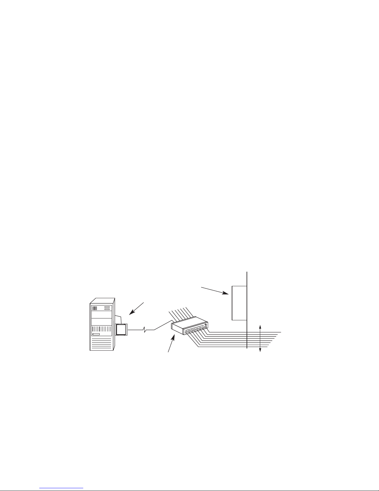
The Model 58x is also well suited for use in severe lightning areas,
heavy industrial environments, and situations where heavy machinery
is in the direct vicinity of sensitive LAN equipment and cabling. Figure
2 (below) shows a typical application for the Model 58x. For best
results, the braided grounding strap(s) on the Model 58x should be
attached to the grounded metal frame of the device being protected.
When installation is made at a barrier, such as an external wall, the
braided strap must be connected to a nearby electrical ground. If a
nearby electrical ground cannot be located, contact Patton Technical
Support (See Section 1.1).
Model 57x or 58x
To Other
Building or
Wall
Exterior Wall
Electrical Panel
4
Model 580
Figure 2. Barrier Application for 58x
Page 6

Page 7

3.2.2 Connecting the Model 58x at a Barrier (Wall,
Building, Entrance, etc.)
1. Disconnect the UTP cable from the wall jack or patch panel jack.
2. Install the Model 58x between the UTP line and the jack. This
installation requires a straight through Cat-5 patch cable with
modular RJ-45 male connectors.
Note: It doesn’t matter which port the UTP cable plugs into on the
rack, ss long as the input is directly above or below the corresponding output.
3. Connect the ground braid(s) to the rack frame according to Figure
4 connected to earth ground. Do not lengthen the ground strap
or section describes connection procedures for both models.
4. Connect the rack structure frame directly to the earth ground if it is
not already connected. The best way to make this ground connection is to attach a thick braided metal strap earth ground to a
metal panel, a wall plate screw or an electrical panel or subpanel,
using a hex nut or ground screw. Pay close attention to the important note in Figure 4. If you cannot locate a nearby electrical
ground, contact Patton Electronics Technical Service (see Section
1.1)
Caution
: Surge energy may run both directions on the ground
strap. To provide the best protection, it is essential that the supplied ground strap on the 57x/58x is connected to the chassis
ground of the protected device. Do not lengthen the ground strap
or connect to a ground other than a chassis ground unless
instructed to do so by Patton Technical Support.
6
Page 8

Page 9

APPENDIX B
INTERNATIONAL ELECTROTECHNICAL COMMISSION (IEC) COM-
PLIANCE
Meets IEC standards 801.2, 801.4 and 801.5 (CE Mark)
Effective January 1996 the European Economic Community will
require that all electronic devices be tested and comply with all applicable International standards relating to the product type and category
of use. Electromagetic Compatibility Directive 89/336/EEC specifically
addresses communication line surge protection devices, since conformity to immunity standard EN50082-1:1992 is mandatory. The
EN50082-1:10992 standard incorporates International Organization for
Standardization (ISO) publications 801.2 and 801.4, which describe
Electrostatic Discharge and Electrical Fast Transient requirements.
ISO 801.5 describes Surge Immunity Requirements and is expected to
be adopted as a mandatory requirement under EN50082-1 by the
Technical Committee. in 1996. Any protector sold into the international
community must meet these standards. This device has been tested*
and found to comply with these standards as evidenced by its CE
mark.
*Note: All test results are for the Model 57x/58x
alone
, not including
any external patch cables that are connected to the unit.
Class
11.0 kV
24 A
21.0 kV
24 A
32.0 kV
48 A
4 (n/a)
(n/a)
54.0 Kv
95 A
Wave (1.2 x 50 μs)
Forms (1.2 x 50 μs)
IEC 801-5 Threat Levels as a Function of Class
Sym. Lines Coupling Mode
Line-GND, Zs=42 Ohms
Figure B-1. IEC Threat Levels as a Function of Class.
Page 10

Page 11

APPENDIX C (continued)
TSB-40A COMPLIANCE TESTING RESULTS
TYPICAL ATTENUATION MEASUREMENT
Freq Pins: 1-2 Pins: 3-6 Pins: 4-5 Pins:7-8 Spec
MHz dB dB dB dB dB
1 0.0 0.0 0.0 0.1 0.1
4 0.1 0.1 0.1 0.0 0.1
8 0.0 0.1 0.1 0.1 0.1
10 0.0 0.0 0.1 0.0 0.1
16 0.1 0.1 0.1 0.0 0.2
20 0.1 0.1 0.2 0.0 0.2
25 0.0 0.0 0.1 0.0 0.2
35.25 0.0 0.1 0.2 0.0 0.2
62.5 0.2 0.1 0.3 0.0 0.3
100 0.4 0.3 0.4 0.3 0.4
Freq Pins: 1-2 Pins: 3-6 Pins: 4-5 Pins:7-8 Spec
MHz dB dB dB dB dB
1 0.1 0.0 0.1 0.1 0.1
4 0.1 0.1 0.0 0.1 0.1
8 0.0 0.1 0.0 0.1 0.1
10 0.1 0.1 0.1 0.1 0.1
16 0.1 0.1 0.1 0.1 0.2
20 0.1 0.2 0.0 0.2 0.2
25 0.0 0.1 0.1 0.1 0.2
35.25 0.0 0.1 0.0 0.1 0.2
62.5 0.1 0.2 0.1 0.2 0.3
100 0.4 0.3 0.4 0.3 0.4
Figure C-3. Attenuation Measurements for Patton Model 57x
Figure C-4. Attenuation measurements for Patton Model 58x
Page 12

Page 13

Appendix C (continued)
TSB-40A Compliance Testing Results
TYPICAL INSERTION LOSS MEASUREMENT
12
Pin Number: DC Resistance
Milliohms
1 180
2 190
3 180
4 190
5 180
6 120
7 190
8 180
Pin Number: DC Resistance
Milliohms
1 180
2 180
3 180
4 190
5 190
6 120
7 180
8 160
Figure C-7. Patton Model 57x Series Insertion Loss Measurement
Figure C-8.Patton Model 58x Series Insertion Loss Measurement
Page 14

Page 15

Page 16

 Loading...