

Page 1
USER
MANUAL
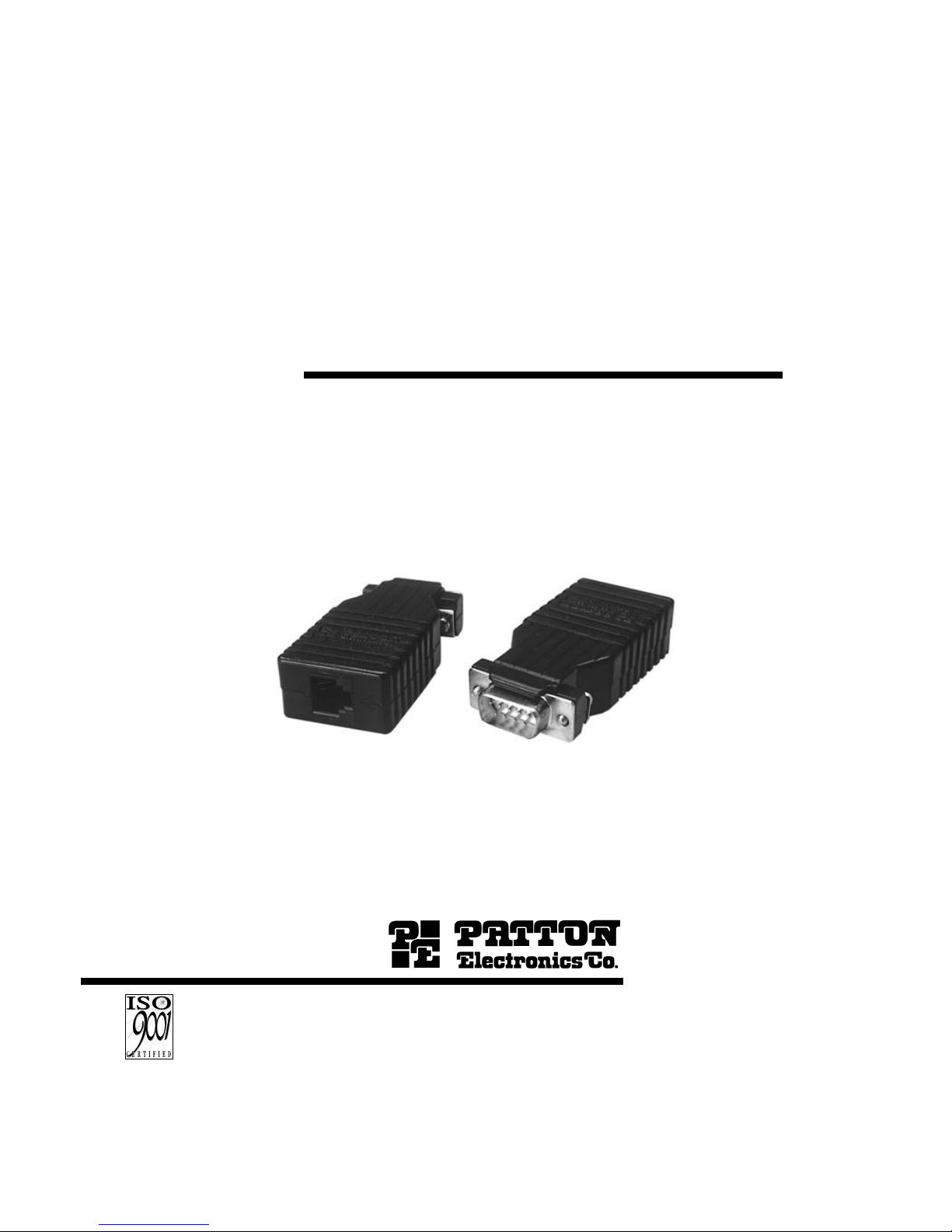
MODEL 506 & 507
Surge Protected
DB-9 to Modular Adapters
SALES OFFICE
(301) 975-1000
TECHNICAL SUPPORT
(301) 975-1007
http://www.patton.com
Part #07M506/507-B
Doc. #019061U
Rev. C
Revised 1/21/08
CERTIFIED
An ISO-9001
Certified Company
Page 2

1.0 WARRANTY INFORMATION
Patton Electronics warrants all Model 506 & 507 components to
be free from defects, and will—at our option—repair or replace the
product should it fail within one year from the first date of shipment. This
warranty is limited to defects in workmanship or materials, and does not
cover customer damage, abuse or unauthorized modification. If this
product fails or does not perform as warranted, your sole recourse shall
be repair or replacement as described above. Under no condition shall
Patton Electronics be liable for any damages incurred by the use of
this product. These damages include, but are not limited to, the
following: lost profits, lost savings and incidental or consequential
damages arising from the use of or inability to use this product. Patton
Electronics specifically disclaims all other warranties, expressed or
implied, and the installation or use of this product shall be deemed an
acceptance of these terms by the user.
1.1 RADIO AND TV INTERFERENCE
The Model 506 & 507 Series units generate and use radio
frequency energy, and if not installed and used properly—that is, in strict
accordance with the manufacturer's instructions—may cause
interference to radio and television reception. They have been tested
and found to comply with the limits for a Class A computing device in
accordance with the specifications in Subpart J of Part 15 of FCC rules,
which are designed to provide reasonable protection from such
interference in a commercial installation. However, there is no
guarantee that interference will not occur in a particular installation. If
these products do cause interference to radio or television reception,
which can be determined by turning off the unit, the user is encouraged
to try to correct the interference by one or more of the following
measures: moving the computing equipment away from the receiver, reorienting the receiving antenna and/or plugging the receiving equipment
into a different AC outlet (such that the computing equipment and
receiver are on different branches).
1.2 CE NOTICE
The CE symbol on your Patton Electronics equipment indicates that
it is in compliance with the Electromagnetic Compatibility (EMC)
directive and the Low Voltage Directive (LVD) of the Union European
(EU). A Certificate of Compliance is available by contacting Technical
Support.
1
Page 3

Page 4

2.0 GENERAL INFORMATION
Thank you for your purchase of this Patton Electronics product.
This product has been thoroughly inspected and tested and is
warranted for One Year parts and labor. If any questions arise during
installation or use of the unit, contact Patton Electronics Technical
Support at (301)975-1000.
2.1 PRODUCT DESCRIPTION
The Patton Model 506 & 507 Surge Protected DB-9 to Modular
Adapters allow you to simplify cabling connections and protect your
RS-232 or RS-422 DB-9 equipment at the same time. Each adapter is
custom wired according to your
pin-out diagram (no “standard” wiring).
Up to 1500 Watts of surge protections per modular pin is provided. On
the Models 506, an RJ-11 jack is used, and up to 6 pins may be
protected. On the Model 507, an RJ-45 jack is used, and up to 8 pins
may be protected. Both the Model 506 and 507 employ Silicon
Avalanche Diodes for superior transient protection. You may specify a
clamping voltage of 27V for RS-232 applications or 6.8V for RS-422
applications. Surges are shunted safely to chassis ground through the
D-shell connector. Male or female DB-9 connectors are available.
Warning: These products will not provide complete protection
should your equipment be subject to a direct lightning hit.
2.2 SURGE PROTECTION BENEFITS
The method of surge protection used in the Models 506 & 507
adds four benefits to your system:
1)
High Surge Capacity
. The Models 506 & 507 dissipate up to
1500 Watts per wire in 1.0 millisecond.
2)
Quick Response.
The Models 506 & 507 have a fast
response time of 1 picosecond; 0.5 microsecond installed.
3)
Low Impedance.
The Models 506 & 507 add minimal load to
your system--about the same as a gender changer.
4)
Open Failure.
The Models 506 & 507 fail “open” if your
system experiences a severe transient or power fault above
the rated voltage of the protector. This means that data and
surge energy is shunted directly to chassis ground, rather that
being allowed to flow throughout the system.
3
Page 5

Page 6

APPENDIX A
MODEL 506 & 507 SPECIFICATIONS
Peak Power Dissipation: 1500W, 10 x 1000μSec in Compliance
with IEC 801-5 Level 3, 2kV (Models
506F/25, 506M/25, 507F/25,
507M/25, 507X)
Response Time: (RS-232) Clamped to ± 27V after
0.5μsec.
(RS-422) Clamped to ± 6.8V after
0.5μsec.
Breakdown Voltages: 27V for RS-232, 6.8V for RS-422
Capacitance: less than 500pF
Cable Length Burden: less than 9.1” (2.8m)
Copyright © 1997
Patton Electronics Company
All Rights Reserved
5
Page 7

Page 8

 Loading...