

Page 1
USER
MANUAL
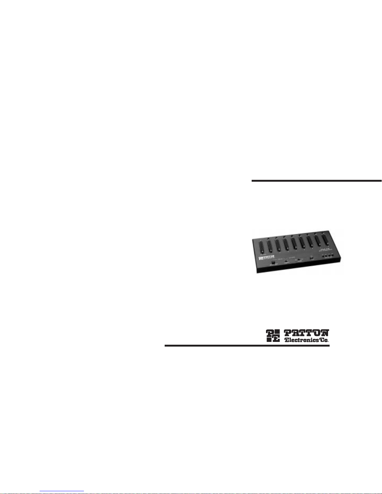
MODEL 378S
Serial Scanning Switch
SALES OFFICE
(301) 975-1000
TECHNICAL SUPPORT
(301) 975-1007
http://www.patton.com
Part# 07M378S-B
Doc# 020011UB
Revised 4/20/93
Page 2

1.0 WARRANTY INFORMATION
Patton Electronics warrants all Model 378S components to be
free from defects, and will--at our option--repair or replace the product
should it fail within one year from the first date of shipment.
This warranty is limited to defects in workmanship or materials,
and does not cover customer damage, abuse, or unauthorized modification. If this product fails or does not perform as warranted, your sole
recourse shall be repair or replacement as described above. Under no
condition shall Patton Electronics be liable for any damages incurred
by the use of this product. These damages include, but are not limited
to, the following: lost profits, lost savings, and incidental or consequential damages arising from the use of or inability to use this product.
Patton Electronics specifically disclaims all other warranties,
expressed or implied, and the installation or use of this product shall
be deemed an acceptance of these terms by the user.
1.1 RADIO AND TV INTERFERENCE
The Model 378S generates and uses radio frequency energy, and
if not installed and used properly--that is, in strict accordance with the
manufacturer's instructions--may cause interference to radio and television reception. The Model 378S has been tested and found to comply
with the limits for a Class A computing device in accordance with the
specifications in Subpart J of Part 15 of FCC rules, which are designed
to provide reasonable protection from such interference in a commercial installation. However, there is no guarantee that interference will
not occur in a particular installation. If the Model 378S does cause
interference to radio or television reception, which can be determined
by disconnecting the RS-232 interface, the user is encouraged to try to
correct the interference by one or more of the following measures:
moving the computing equipment away from the receiver, re-orienting
the receiving antenna, and/or plugging the receiving equipment into a
different AC outlet (such that the computing equipment and receiver
are on different branches).
1.2 SERVICE
All warranty and non-warranty repairs must be returned freight
prepaid and insured to Patton Electronics. All returns must have a
Return Materials Authorization number on the outside of the shipping
container. This number may be obtained from Patton Electronics
Technical Service at (301) 975-1007.
Packages received without an
RMA number will not be accepted.
Patton Electronics' technical staff is also available to answer any
questions that might arise concerning the installation or use of your
Model 378S. Technical Service hours: 8AM to 5PM EST, Monday
through Friday.
1
2.0 GENERAL INFORMATION
Thank you for your purchase of this Patton Electronics product.
This product has been thoroughly inspected and tested and is warranted for One Year parts and labor. If any questions or problems arise
during installation or use of this product, please do not hesitate to contact Patton Electronics Technical Support at (301)-975-1007.
2.1 FEATURES
• Lets 8 PCs share one serial printer or plotter
• Supports data rates to 19.2 Kbps on inputs and output
• Supports both hardware (CTS/DSR) and software (X-ON/X-OFF)
flow control
• Available with up to 1 Meg of RAM buffer
• Individual port LEDs show scanning progress and which port is
loading data
• Buffer status LEDs show amount of buffer currently being used
• Manual override lets you select a port and give it exclusive printer
access
• Variable time outs allow adjustment of waiting time between the
end of data downloading and the resumption of scanning
• Buffer clear button lets you erase the buffer's memory
2.2 DESCRIPTION
The Model 378S Serial Scanning Switch provides an easy way
for as many as eight PCs to share a single serial printer. Equipped
with up to 1Meg of buffer, the Model 378S scans all input ports once
every two seconds to see if any device is sending data. As soon as
the Model 378S locates a device sending data, it locks on to that
device and loads all its data to buffer. Then the Model 378S simultaneously spools the data to the printer or plotter and resumes scanning.
The Model 378S allows input/output data rates to 19.2Kbps, and
supports both hardware (CTS/DSR) and software (X-ON/X-OFF) handshaking methods. Convenience features of the Model 378S include a
manual "step" button that overrides automatic scanning, and a master
buffer clear button. Two sets of LED indicators are provided: one set
shows which port is currently being scanned or loaded, the other set
shows the percentage of buffer space currently available.
2
Page 3

3.0 CONFIGURATION
This section tells how to set the internal DIP switches for the Model
378S, and details the factory default DIP switch settings.
3.1 ACCESSING THE INTERNAL SWITCHES
To configure the Model 378S, you must first open the case by taking off the 4 screws (2 on each side). Then locate the DIP switches
(shown below) at the lower center of the PC board:
3.2 SWITCH SETTINGS
The individual descriptions below and the table on the following
page detail all possible configuration switch settings. You
must set the
internal DIP switches
to match the configuration of your PCs and printer
or the Model 378S will not function properly.
sw1-1-3, BAUD RATE: SW1-1, SW1-2, and SW1-3 are used to set
the 378S internal baud rate. Whichever baud rate setting you choose, it
must match the baud rate settings of your PCs and printer.
SW1-4, WORD LENGTH: The 378S will accept either 7 (OFF) or 8
(ON) data bits, selectable by SW1-4. Again, the setting of this switch
must match the PC and printer settings. Either format may use one or
two stop bits (See SW1-7).
SW1-5, PARITY ENABLE: SW1-5 enables (ON) or disables (OFF)
parity. With parity enabled, the 378S accepts an even or odd parity bit
(See SW1-5).
SW1-6, PARITY TYPE: The 378S accepts either even (OFF) or odd
(ON) parity. In order for SW1-6 to operate properly, SW1-5 (Parity
Enable) must be in the ON position.
43
SW1-7, STOP BITS: Use SW1-7 to set the number of Stop Bits to 1
(OFF) or 2 (ON).
SW1-8 & 9, TIMEOUT: After the last data bit is received from the
currently selected port, SW1-8 and SW1-9 determine how long the
378S waits before moving on to the next port. Text and word processing files generally need a very short timeout setting. Larger graphics
files may require longer timeout settings.
SW1-10, FORM FEED AT EOJ: With SW1-10 disabled (OFF), the
378S will not issue a Form Feed at the End Of Job. Any text or word
processing form feeds or blank pages will print as normal. With SW110 enabled, the 378S will form feed one page at EOJ (see Appendix A
for more information about Form Feed at EOJ).
12345678910
ON
Data Rate
Data Rate
Data Rate
Word Lengt
h
Parity Ena
bl
Parity T ype
Stop Bits
Timeout
Timeout
Form Feed E
O
ON
OFF
SWITCH CONFIGURATION TABLE
Switch Position Function Options Settings
SW1-1 SW1-2 SW1-3
SW1-1,2,3 Data Rate 1200 Off Off Off
2400 Off Off On
4800 Off On Off
9600 Off On On
19,200 On Off Off
SW1-4
SW1-4 Word Length 7 data bits Off
8 data bits On
SW1-5
SW1-5 Enable
Disable Off
Enable On
SW1-6
SW1-6 Type Even Off
Odd On
SW1-7
SW1-7 Stop Bits
1 Stop bit Off
2 Stop bits On
SW1-8 SW1-9
SW1-8,9 Timeout
2 Seconds Off Off
8 Seconds Off On
60 Seconds On Off
120 Seconds On On
SW1-10
SW1-10 Form Feed
Disable Off
at End of Job Enable On
P
A
R
I
T
Y
Bold Italics = Factory Setting
Page 4

4.0 INSTALLATION
This section explains how the Model 378S handles flow control,
describes input/output cable connections, and tells how to operate the
Model 378S.
4.1 FLOW CONTROL CAPABILITIES
The Model 378S supports both software and hardware flow control
on all ports. There is no need to configure the switch for one method or
the other. However the input (PC) ports operate differently than the
output (printer) port with respect to flow control.
The selected PC and the printer never communicate directly.
Though it "appears" to the devices that they are communicating with
one another, each is actually communicating only with the Model 378S.
The Model 378S manages this communications traffic in the following
manner:
1) The Model 378S flow controls incoming data from the selected
PC by controlling CTS/DSR (hardware handshaking) or XON/XOFF
(software handshaking). PCs cannot flow control incoming data from
the printer or from the Model 378S.
2) The Model 378S retains unlimited use of the printer by keeping
RTS constantly high.
3) The printer flow controls data from the Model 378S using CTS
or XON/XOFF.
4.2 INPUT CABLE CONNECTIONS
All input ports are configured as DCE (Data Communication
Equipment): They are designed to connect directly to a PC or another
DTE (Data Termination Equipment) device using
straight through
cables
. If you are using XON/XOFF handshaking, then the only
required pins are pins 2, 3, and 7. If you use hardware handshaking,
then pin 5 or 6 must also be connected. The input port signals and
pins are shown below:
PIN SIGNAL DESCRIPTION
2 TD Data INPUT to Model 378S from PC
3 RD OUTPUT from 378S to PC (used
for XON/XOFF flow control only)
(continued)
5 CTS OUTPUT from 378S to PC: Internally
connected to pin 6. Held low--toggles high
when port is chosen
6 DSR OUTPUT from 378S to PC: Internally
connected to pin 5. Held low--toggles high
when port is chosen
7 SG Signal ground
8 CD OUTPUT from 378S at +V to PC
4.3 OUTPUT CABLE CONNECTIONS*
The output port is configured as a DTE: It is designed to connect
directly to a serial printer or plotter. The output port pin descriptions
are shown below:
PIN SIGNAL DESCRIPTION
2 TD Data OUTPUT from Model 378S to printer
3 RD INPUT to 378S from printer (used for
XON/XOFF flow control only)
4 RTS OUTPUT from 378S at +V to printer
5 CTS Flow control bus connection from printer
(used for CTS/DSR flow control only)
7 SG Signal ground
8 CD Not used
20 DTR OUTPUT from 378S at +V to printer
*Note: The output (printer) port of the Model 378S, being configured
as a DTE, requires a female to male
crossover cable
pinned as fol-
lows:
Connection to 378S Connection to Printer
DB-25 Female Pin No. DB-25 Male Pin No.
2.....................................................3
3.....................................................2
4.....................................................5
5.....................................................20
7.....................................................7
20...................................................6 & 8
5 6
Page 5

4.4 OPERATING THE MODEL 378S
After the Model 378S is properly configured and the cables are
connected correctly, you are ready to operate the unit.
1) Turn the Power switch "on"
2) The Model 378S has three operating modes: Automatic Scan,
Manual Scan and Manual Step. These three modes are described
below:
Automatic Scan Mode - In this operating mode, the Model 378S
scans all ports every two seconds in a round-robin manner. When
it "discovers" a port with data to send, the Model 378S locks onto
that port and receives the data into its buffer (units without buffer
send the data directly to the printer).
To enter Automatic Scan Mode, set the Auto/Manual
switch to
"Auto". In this mode, you cannot manually interrupt the scanning
process.
Manual Scan Mode - In this operating mode, the Model 378S
scans all ports in a round-robin manner until it reaches the port
you want it to lock onto. It will then stay at that port unil you scan
again.
To enter Manual Scan Mode, set the Auto/Manual
switch to
"Manual". Then press the Step button and hold it down until the
scanner reaches the desired port. When you remove pressure
from the button, the scanner will stop at that port. Note: Using
this method, you can bypass other ports that have data to send to
the Model 378S.
Manual Step Mode - In this operating mode, the Model 378S
scans all ports, one at a time, until it reaches the port you want it
to lock onto. It will then stay at that port unil you scan again.
To enter Manual Step Mode, set the Auto/Manual
switch to
"Manual". Then press the Step button repeatedly until the scanner
reaches the desired port.
3) Use the Reset button when you want to clear the Model 378S's
buffer of all contents. This button is only operational in buffered units.
APPENDIX A
MODEL 378S SPECIFICATIONS
Input Interface
EIA RS-232 Serial. 25-pin DB Female DCE (modem) connector
Use Standard Straight-thru cable
Output Interface
EIA RS-232 Serial. 25-pin DB Male DTE (PC) connector
Uses standard IBM-to-Printer Cables
Scanning Priorities
Manual Mode–
Step through by operator push button
Automatic Mode–
Continue scanning to the next sequential input
port. The next port is chosen only after the selected time-out expires
(refer to DIP switch positions S1-8,9)
Front Panel Controls
Power Switch–
On/Off.
Auto/Manual Switch–
AUTO mode continues after timeout interval
with next in line. All ports are scanned in two seconds. MANUAL
mode turns port selection over to the operator in conjunction with the
STEP button.
Step Button-
(MANUAL mode only) Disables currently selected port
and locks onto the next port. If held, STEP auto-repeats to skip over
several ports to reach a desired port. This action prevents an input
port from ‘grabbing control’ while being skipped over via STEP.
Reset Button-
Resets and clears entire buffer memory.
LED Indicators
Port Select-
Port is being polled for data
Buffer Status-
Buffer is up to 25%, 50%, 75% or 100% full. 1) While
the input port is receiving data, all buffer status LEDs will “blink” 2) If
no data is being received, but some data remains in the buffer, the
appropriate number of LEDs will glow steadily (this applies only to
units with RAM modules). 3) After the buffer is emptied out to the
printer, all LEDs will turn off.
7 8
Page 6

Buffer Options
The 378S comes factory-configured with different amounts of buffer
memory. Versions are available with no RAM, 256 KB RAM, and 1 MB
dynamic RAM. Contact Patton Technical Support at 301-975-1007 for
details on upgrades.
Communication Parameters
Data Rate–
All ports share a common data rate. The data rate is
selected via DIP SWITCHES for one of five rates: 1200, 2400, 4800,
9600, or 19,200 baud.
Parity–
Even/Odd/None
Word Length–
7 or 8 Bits
Flow Control–
Incoming PC data is flow controlled by the switch
using CTS/DSR or XON/XOFF. This flow control is unidirectional -only data coming from the PC can be flowed off, not data coming from
the printer
back
to the PC. Transmitted data to the PC consists of
XON/XOFF flow control characters.
Configuration Switches
Baud Rate-
1200, 2400, 4800, 9600, or 19200
Word Length-
7 or 8 data bits
Parity Enable-
Enabled/Disabled
Parity Type-
Even/Odd
Stop Bits-
1 or 2
Timeout Interval-
2, 8, 60, 120 seconds
Form Feed at EOJ-
Enabled/Disabled
(Note: The Model 378S has a "paper saver" feature that is active only
when "Form Feed at EOJ" switch is enabled. When the paper saver
feature is active, the switch monitors whether or not the last character
sent by the selected PC was a form feed. If it was, the switch will
decline to insert its own form feed character [carriage returns inserted
by the PC after form feed are ignored]).
Power
9.8VAC, 800 MA Wall mount transformer
Size
10”W X 5”D x 1”H (approximate).
APPENDIX B
RS-232C PIN CONFIGURATIONS
1- (FG) Frame Ground
2- (TD) Transmit Data To Model 378S
3- (RD) Receive Data From Model 378S
4- (RTS) Request to Send To Model 378S
5- (CTS) Clear to Send From Model 378S
6- (DSR) Data Set Ready From Model 378S
7- (SG) Signal Ground
8- (DCD) Data Carrier Detect From Model 378S
DIRECTION MODEL 378S "DCE" SETTING DIRECTION
1- (FG) Frame Ground
2- (TD) Transmit Data From Model 378S
3- (RD) Receive Data To Model 378S
4- (RTS) Request to Send From Model 378S
5- (CTS) Clear to Send To Model 378S
7- (SG) Signal Ground
DIRECTION MODEL 378S "DTE" SETTING DIRECTION
9 10
To Model 378S Data Term. Ready (DTR) - 20
 Loading...