

Page 1
For Quick
Start Installation
see page 21
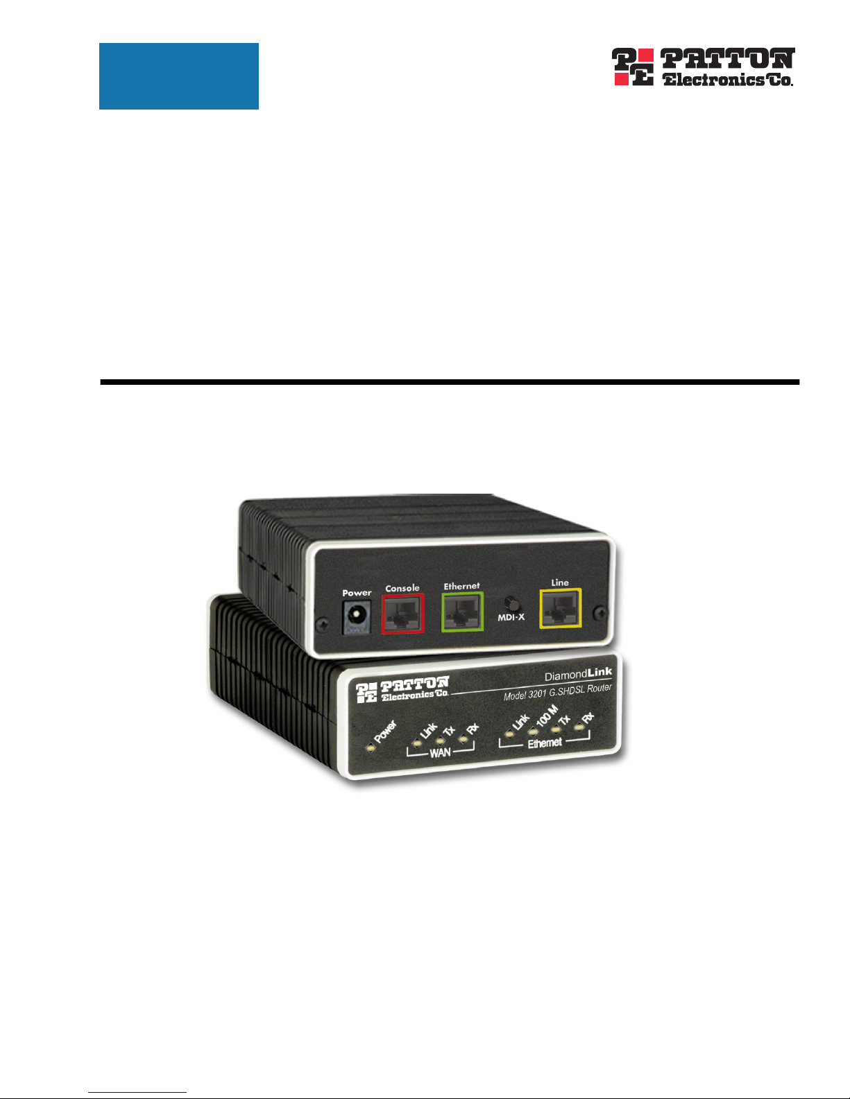
Model 3201 and Model 3241
G.SHDSL Router
Modems
User Guide
Sales Office: +1 (301) 975-1000
Technical Support: +1 (301) 975-1007
E-mail: support@patton.com
URL: www.patton.com
Document Number: 0xxxxxU Rev. A
Part Number: 07MD3201
Revised: January 27, 2003
Page 2

Patton Electronics Company, Inc.
7622 Rickenbacker Drive
Gaithersburg, MD 20879 USA
tel: +1 (301) 975-1000
fax: +1 (301) 869-9293
support: +1 (301) 975-1007
web: www.patton.com
e-mail: support@patton.com
Copyright © 2002 & 2003, Patton Electronics Company. All rights reserved.
The information in this document is subject to change without notice. Patton Elec-
tronics assumes no liability for errors that may appear in this document.
Page 3

Contents
Contents ......................................................................................................................................................... 1
Compliance Information ................................................................................................................................ 5
Radio and TV Interference ...............................................................................................................................5
CE Notice .........................................................................................................................................................5
FCC Part 68 .....................................................................................................................................................5
Industry Canada Notice ....................................................................................................................................6
Service ..............................................................................................................................................................6
About this guide ............................................................................................................................................. 7
Audience................................................................................................................................................................. 7
Structure................................................................................................................................................................. 7
Precautions ............................................................................................................................................................. 8
Factory default parameters...................................................................................................................................... 8
Typographical conventions used in this document.................................................................................................. 9
General conventions .........................................................................................................................................9
Mouse conventions ...........................................................................................................................................9
1 General Information...................................................................................................................................... 11
Model 3201/3241 G.SHDSL Router Modem overview ........................................................................................12
General attributes ............................................................................................................................................12
G.SHDSL Characteristics (Models 3201 and 3241) .......................................................................................12
Ethernet ..........................................................................................................................................................12
Protocol support .............................................................................................................................................13
PPP Support ...................................................................................................................................................13
ATM Protocols ...............................................................................................................................................13
Management ...................................................................................................................................................13
Security ...........................................................................................................................................................13
Front Panel Status LEDs .......................................................................................................................................14
Rear panel connectors and switches .................................................................................................................14
Power input connector ....................................................................................................................................15
External AC universal power supply ..........................................................................................................15
External 48 VDC power supply ................................................................................................................15
Console port (outlined in red) .........................................................................................................................16
Ethernet port (outlined in green) ....................................................................................................................16
MDI-X ...........................................................................................................................................................16
Line port (outlined in yellow) .........................................................................................................................16
2 Product Overview.......................................................................................................................................... 17
Product Overview..................................................................................................................................................18
Applications Overview ....................................................................................................................................18
3 Quick Start Installation................................................................................................................................. 21
Hardware installation ............................................................................................................................................22
1
Page 4

Contents
Model 3201 G.SHDSL Integrated Access Device User Guide
What you will need .........................................................................................................................................22
Identify the connectors and attach the cables ..................................................................................................22
IP address Quick Start modification ................................................................................................................23
Router/Bridge Status LEDs .......................................................................................................................24
Web Operation and Configuration .................................................................................................................24
PC Configuration .....................................................................................................................................24
Web Browser .............................................................................................................................................24
4 Basic Application Configurations.................................................................................................................. 27
Introduction..........................................................................................................................................................28
Two stand-alone units directly connected..............................................................................................................29
Ethernet Extension (HDLC - PPPoH Bridged) ..............................................................................................29
Network Extension (HDLC—PPPoH Routed) ..............................................................................................32
DSLAM Connections with remote CPE units.......................................................................................................38
Bridged application configurations to a DSLAM ............................................................................................38
RFC 1483 Bridged Configuration. ............................................................................................................38
PPPoH Bridged Configuration .................................................................................................................41
PPPoA Bridged (RFC 2364) Configuration ..............................................................................................44
Routed application configurations to a DSLAM .............................................................................................46
RFC 1483 Routed .....................................................................................................................................46
PPPoH Routed .........................................................................................................................................53
PPPoA Routed (RFC 2364) ......................................................................................................................60
IPoA Routed (RFC 1577) ........................................................................................................................72
5 Specialized Configurations............................................................................................................................ 79
IP Configurations..................................................................................................................................................80
Router .............................................................................................................................................................80
DHCP Server and Relay .................................................................................................................................81
6 Security ......................................................................................................................................................... 85
Introduction..........................................................................................................................................................86
Configuring the router ..........................................................................................................................................86
Configuring the security interfaces.........................................................................................................................87
Deleting a Firewall Policy ...............................................................................................................................88
Enabling the Firewall.............................................................................................................................................89
Firewall Portfilters .................................................................................................................................................89
Security Triggers....................................................................................................................................................90
Intrusion Detection System (IDS) .........................................................................................................................91
7 NAT (Network Address Translation) ............................................................................................................ 95
Introduction..........................................................................................................................................................96
Enabling NAT ................................................................................................................................................96
Global address pool and reserved map .............................................................................................................97
8 Monitoring Status ......................................................................................................................................... 99
Status LEDs.........................................................................................................................................................100
9 Diagnostics.................................................................................................................................................. 101
2
Page 5

3
Model 3201 G.SHDSL Integrated Access Device User Guide
Contents
Ping.....................................................................................................................................................................102
Software Upgrades...............................................................................................................................................102
Configuration ...............................................................................................................................................102
Procedure ......................................................................................................................................................102
10 Contacting Patton for assistance ................................................................................................................. 105
Introduction........................................................................................................................................................106
Contact information............................................................................................................................................106
Warranty Service and Returned Merchandise Authorizations (RMAs).................................................................106
Warranty coverage ........................................................................................................................................106
Out-of-warranty service ...........................................................................................................................106
Returns for credit ....................................................................................................................................106
Return for credit policy ...........................................................................................................................107
RMA numbers ..............................................................................................................................................107
Shipping instructions ..............................................................................................................................107
A Specifications .............................................................................................................................................. 109
General Characteristics ........................................................................................................................................110
G.SHDSL Characteristics (Model 3201/3241)....................................................................................................110
Ethernet ..............................................................................................................................................................110
Protocol Support .................................................................................................................................................111
PPP Support........................................................................................................................................................111
ATM Protocols....................................................................................................................................................111
Management .......................................................................................................................................................112
Security ...............................................................................................................................................................112
Compliance Standard Requirements....................................................................................................................112
Australia Specific .....................................................................................................................................112
Dimensions .........................................................................................................................................................113
Power and Power Supply Specifications...............................................................................................................113
B Cable Recommendations ............................................................................................................................ 115
DSL Cable...........................................................................................................................................................116
Ethernet Cable ....................................................................................................................................................116
Adapter................................................................................................................................................................116
C Physical Connectors ................................................................................................................................... 117
RJ-45 shielded 10/100 Ethernet port...................................................................................................................118
RJ-11 non-shielded port ......................................................................................................................................118
RJ-45 non-shielded RS-232 console port (EIA-561)............................................................................................118
Power input.........................................................................................................................................................118
D Command Line Interface (CLI) Operation ................................................................................................ 119
Introduction........................................................................................................................................................120
CLI Terminology ................................................................................................................................................120
Local (VT-100 emulation) ............................................................................................................................120
Remote (Telnet) ............................................................................................................................................120
Using the Console .........................................................................................................................................121
Page 6

Contents
Model 3201 G.SHDSL Integrated Access Device User Guide
Administering user accounts................................................................................................................................122
Adding new users ..........................................................................................................................................122
Setting user passwords ...................................................................................................................................123
Changing user settings ..................................................................................................................................123
Controlling login access ...........................................................................................................................123
Controlling user access ............................................................................................................................124
G.SHDSL Commands: .................................................................................................................................124
To establish the DSL link ........................................................................................................................124
4
Page 7

1.
Compliance Information
and TV
Radio
The Model 3201 or 3241 generates and uses radio frequency energy, and if not installed and used properlythat is, in strict accordance with the manufacturer’s instructions-may cause interference to radio and television
reception. The Models 3201 and 3241 have been tested and found to comply with the limits for a Class A
computing device in accordance with specifications in Subpart B of Part 15 of FCC rules, which are designed
to provide reasonable protection from such interference in a commercial installation. However, there is no
guarantee that interference will not occur in a particular installation. If the Model 3201 or 3241 does cause
interference to radio or television reception, which can be determined by disconnecting the unit, the user is
encouraged to try to correct the interference by one or more of the following measures: moving the computing
equipment away from the receiver, re-orienting the receiving antenna and/or plugging the receiving equipment
into a different AC outlet (such that the computing equipment and receiver are on different branches).
Interference
CE Notice
The CE symbol on your Patton Electronics equipment indicates that it is in compliance with the Electromagnetic Compatibility (EMC) directive and the Low Voltage Directive (LVD) of the European Union (EU). A
Certificate of Compliance is available by contacting Technical Support.
FCC Part 68
The Model 3201 is not intended to be connected to the public
telephone network.
You are required to request service from the telephone company before you connect the Model 3201 or
3241 to a network. When you request service, you must provide the telephone company with the following data.
— The required Universal Service Order code (USOC) jack: RJ-11C
— The make, model number, Ringer Equivalence Number (REN), and FCC Registration number of the
Model 3201 or 3241.
The REN helps you determine the number of devices you can connect to your telephone line and still have
all of those devices ring when your number is called. In most, but not all, areas, the sum of the RENs of all
devices should not exceed five (5.0). To be certain of the number of devices you can connect to your line,
you should call your local telephone company to determine the maximum REN.
— The Facility Interface Code: 02LS2
— The Service Order Code(s) (SOC): 9.0F
— REN No.: 0.2
2. Your telephone company may make changes to its facilities, equipment, operations, or procedures that
could affect the proper functioning of your equipment. The telephone company will notify in advance of
such changes to give you an opportunity to maintain uninterrupted telephone service.
5
Page 8

4.
5.
3.
Compliance Information
Model 3201 G.SHDSL Integrated Access Device User Guide
If your Model 3201 or 3241 causes harm to the telephone network, the telephone company may temporarily discontinue your service. If possible, they will notify you in advance, but if advance notice is not
practical, you will be notified as soon as possible and will be informed of your right to file a complaint with
the FCC.
If you experience trouble with the Model 3201 or 3241, please contact Patton Electronics Company for
service or repairs. Repairs should be performed only by Patton Electronics Co.
You are required to notify the telephone company when you disconnect the Model 3201 or 3241 from the
network.
Industry Canada Notice
Note
This equipment meets the applicable Industry Canada Terminal
Equipment Technical Specifications. This is confirmed by the registration number. The abbreviation, IC , before the registration number
signifies that registration was performed based on a Declaration of
conformity indicating that Industry Canada technical specifications
were met. It does not imply that Industry Canada approved the
equipment.
Service
All warranty and non-warranty repairs must be returned freight prepaid and insured to Patton Electronics. All
returns must have a Return Materials Authorization number on the outside of the shipping container. This
number may be obtained from Patton Electronics Technical Services at:
• Tel: +1 (301) 975-1007
• Email: support@patton.com
• URL: http://www.patton.com
Note
Packages received without an RMA number will not be accepted.
6
Page 9

About this guide
This guide describes installing and configuring a Patton Electronics Model 3201 or 3241 G.SHDSL Router
modem . The instructions in this guide are based on the following assumptions:
• The router modem will connect to a T1 or E1
• There is a LAN connected to the Ethernet port of the router modem
• Users will be connected to remote router modems
Audience
This guide is intended for the following users:
• Operators
• Installers
• Maintenance technicians
Structure
This guide contains the following chapters and appendices:
• Chapter 1 provides information about router modem features and capabilities
• Chapter 2 contains an overview describing router modem operation
• Chapter 3 provides quick start installation procedures
• Chapter 4 describes configuring the router modem for typical applications
• Chapter 5 describes configuring the router modem for specialized applications
• Chapter 6 describes configuring security for the router modem
• Chapter 7 describes configuring for network address translation (NAT)
• Chapter 8 contains definitions for the LED status indicators
• Chapter 9 describes router modem diagnostics
• Appendix A contains specifications for the router modems
• Appendix B provides cable recommendations
• Appendix C describes the router modem’s ports
• Appendix D describes how to use the command line interface (CLI)
For best results, read the contents of this guide before you install the router modem.
7
Page 10
About this guide
Model 3201 G.SHDSL Integrated Access Device User Guide
Precautions
Notes and cautions, which have the following meanings, are used throughout this guide to help you become
aware of potential Router modem problems. Warnings relate to personal injury issues, and Cautions refer to
potential property damage.
Note
Calls attention to important information.
The shock hazard symbol and WARNING heading indicate a potential electric
shock hazard. Strictly follow the warning instructions to avoid injury caused
by electric shock.
The alert symbol and WARNING heading indicate a potential safety hazard.
Strictly follow the warning instructions to avoid personal injury.
The shock hazard symbol and CAUTION heading indicate a
potential electric shock hazard. Strictly follow the instructions to
avoid property damage caused by electric shock.
The alert symbol and CAUTION heading indicate a potential hazard. Strictly follow the instructions to avoid property damage.
Factory default parameters
The Model 3201/R G.SHDSL router modem has the following factory default parameters.
• Ethernet IP address: 192.168.200.10/24
• WAN Connection: PPPoH Routed
• WAN IP address: 10.1.1.1
• Autonegotiate the G.SHDSL speed.
The Models 3201/I/CP and 3201/I/CO bridge modems have the following factory default parameters.
• Ethernet IP Address:
— 192.168.200.10 (for the CP version)
— 192.168.200.11 (for the CO version)
• Autonegotiate the G.SHDSL speed.
8
Page 11
9
Model 3201 G.SHDSL Integrated Access Device User Guide
Typographical conventions used in this document
This section describes the typographical conventions and terms used in this guide.
General conventions
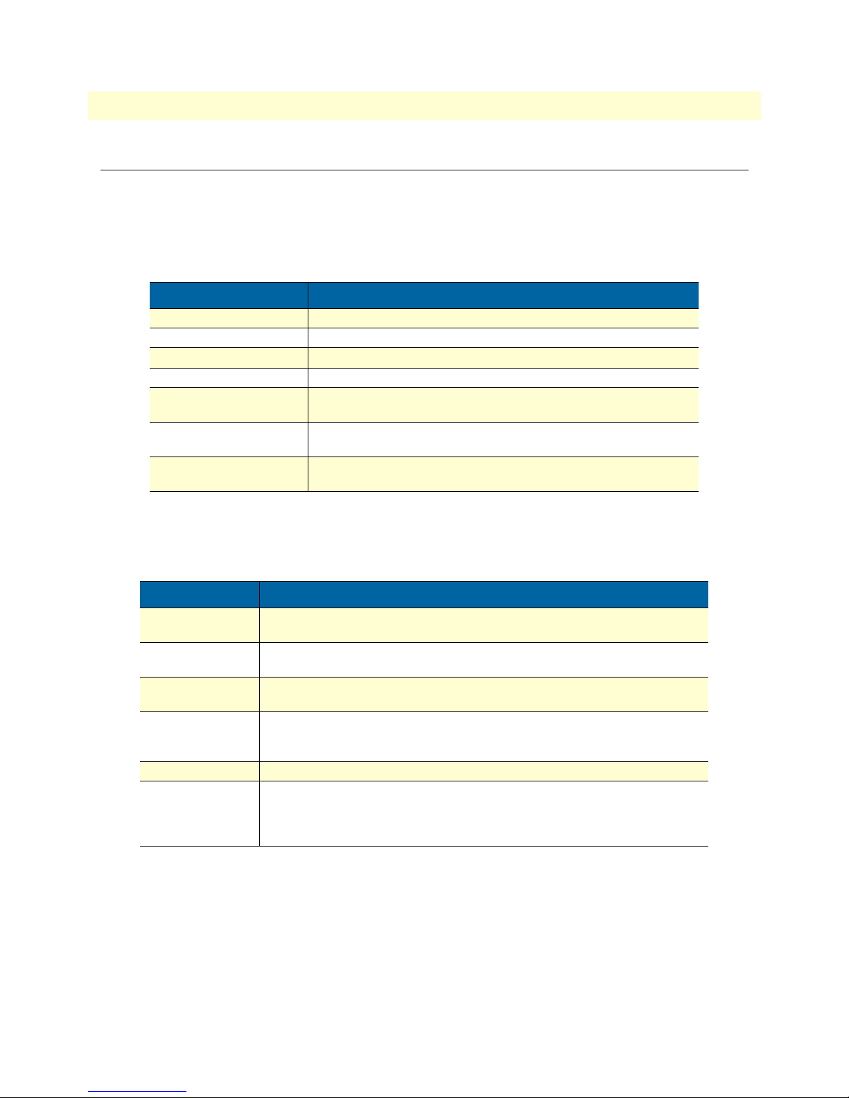
The procedures described in this manual use the following text conventions:
Table 1. General conventions
Convention Meaning
Futura bold type
Italicized Futura type
Futura type
Garamond bold type
< >
Are you ready?
% dir *.*
Indicates the names of menu bar options.
Indicates the names of options on pull-down menus.
Indicates the names of fields or windows.
Indicates the names of command buttons that execute an action.
Angle brackets indicate function and keyboard keys, such as <SHIFT>,
<CTRL>, <C>, and so on.
All system messages and prompts appear in the Courier font as the
system would display them.
Bold Courier font indicates where the operator must type a response or
command
About this guide
Mouse conventions
The following conventions are used when describing mouse actions:
Table 2. Mouse conventions
Convention Meaning
Left mouse button
Right mouse button This button refers the secondary or rightmost mouse button (unless you have
Point This word means to move the mouse in such a way that the tip of the pointing
Click Means to quickly press and release the left or right mouse button (as instructed in
Double-click Means to press and release the same mouse button two times quickly
Drag This word means to point the arrow and then hold down the left or right mouse but-
This button refers to the primary or leftmost mouse button (unless you have
changed the default configuration).
changed the default configuration).
arrow on the screen ends up resting at the desired location.
the procedure). Make sure you do not move the mouse pointer while clicking a
mouse button.
ton (as instructed in the procedure) as you move the mouse to a new location.
When you have moved the mouse pointer to the desired location, you can release
the mouse button.
Page 12

About this guide
Model 3201 G.SHDSL Integrated Access Device User Guide
10
Page 13

Chapter 1 General Information
Chapter contents
Model 3201/3241 G.SHDSL Router Modem overview ........................................................................................12
General attributes ............................................................................................................................................12
G.SHDSL Characteristics (Models 3201 and 3241) .......................................................................................12
Ethernet ..........................................................................................................................................................12
Protocol support .............................................................................................................................................13
PPP Support ...................................................................................................................................................13
ATM Protocols ...............................................................................................................................................13
Management ...................................................................................................................................................13
Security ...........................................................................................................................................................13
Front Panel Status LEDs .......................................................................................................................................14
Rear panel connectors and switches .................................................................................................................14
Power input connector ....................................................................................................................................15
External AC universal power supply ..........................................................................................................15
External 48 VDC power supply ................................................................................................................15
Console port (outlined in red) .........................................................................................................................16
Ethernet port (outlined in green) ....................................................................................................................16
MDI-X ...........................................................................................................................................................16
Line port (outlined in yellow) .........................................................................................................................16
11
Page 14

1 • General Information Model 3201 G.SHDSL Integrated Access Device User Guide
Model 3201/3241 G.SHDSL Router Modem overview
The Patton Models 3201 and 3241 router modems are G.SHDSL routers/bridges for delivering basic and
advanced IP services from the wide-area network to a local 10/100Base-T Ethernet LAN.
G.SHDSL offers an alternative, standards based DSL transmission medium. It offers connection speeds of 2.3
Mbps (Model 3201) or 4.6 Mbps (Model 3241) in each direction over a single twisted-pair (TP). Supporting
100 or more users, the router modems are optimized for users in a small office, as an enterprise tele-working
solution or for multimedia high-speed Internet access. Local and remote web-based management ensures easy
setup and continuous trouble-free operation.
The following sections describe Model 3201 and 3241 features and capabilities:
• General attributes, see page 12
• G.SHDSL Characteristics (Model 3201/3241), see page 12
• Ethernet, see page 12
• Protocol support, see page 13
• PPP support, see page 13
• ATM protocols, see page 13
• Management, see page 13
• Security, see page 13
General attributes
• Compact low-cost plug-and-play router
• 10/100 Ethernet
• Comprehensive hardware diagnostics, works with any operating system, easy maintenance and effortless
installation.
• Built-in web configuration.
• Simple software upgrade using FTP into FLASH memory.
• Eight front panel LEDs indicate Power, DSL WAN, Ethernet LAN speed and status.
• Convenient and standard RJ connectors for Ethernet, Line, and Console.
G.SHDSL Characteristics (Models 3201 and 3241)
• 2.3 Mbps (Model 3201) or 4.6 Mbps (Model 3241) speed over 2 wires.
• DTE rates:
- Model 3201: 144 kbps to 2.32 Mbps, nx64k with n=3 to 36
- Model 3241: 144 kbps to 4.6 Mbps (Model 3241) , nxz64k n=3 to 72.
• Distance from 24,900 feet (7,589 m) at 144kbps (192 kbps line rate) to 10,200 feet (3,109 m) at 2.3 mbps
on 26 AWG (0.4 mm) wire
• CO and CP modes supported
• EOC Management channel for remote end-to-end management.
Ethernet
• Auto-sensing full-duplex 10Base-T/100Base-TX Ethernet.
• Standard RJ-45 and built-in MDI-X cross-over switch.
• IEEE 8021.d transparent learning bridge up to 1,024 addresses and Spanning Tree.
12 Model 3201/3241 G.SHDSL Router Modem overview
Page 15

Model 3201 G.SHDSL Integrated Access Device User Guide 1 • General Information
Protocol support
• Complete internetworking with IP (RFC 741), TCP (RFC 793), UDP (RFC 768), ICMP (RFC 950),
ARP (RFC 826).
• IP Router with RIP (RFC 1058), RIPv2 (RFC 2453) for up to 64 static routes.
• Built-in Ping and Traceroute facilities.
• Integrated DHCP Server (RFC 2131).
• DHCP relay agent (RFC 2132/RFC 1542) with 8 individual address pools.
• DNS Relay with primary and secondary Name Server selection.
• NAT (RFC 3022) with Network Address Port Translation (NAPT), MultiNat with 1:1, Many:1,
Many:Many mapping, Port/IP redirection and mapping.
PPP Support
• Point-to-Point Protocol over HDLC
• PPPoA (RFC 2364) Point-to-Point Protocol over ATM.
• PPPoE (RFC 2516) Client for autonomous network connection. Eliminates the requirement of installing
client software on a local PC and allows sharing of the connection across a LAN.
• User configurable PPP PAP (RFC 1661) or CHAP (RFC 1994) authentication..
ATM Protocols
• Multiprotocol over ATM AAL5 and Multiprotocol Bridged encapsulation RFC 2684 (Formerly RFC
1483) and RFC 1577 Classical IP over ATM. Default RFC-1483 route mode. Logical Link Control
(LLC)/ Subnetwork Access Protocol (SNAP) encapsulation. Default VC mux mode.
• ATM UNI 3.0, 3.1, and 4.0 signaling ATM QoS with UBR, CBR, nrt-VBR, and rt-VBR.
• Peak cell rate shaping on a per-VCC basis up to 32 active VCCs across VPI 0-255, VCI 0-65525. Single
default PVC: 8/35 with PCR=5,500 cells.
Management
• User selectable ATM, PPP, or HDLC WAN datalink connection.
• Web-Based configuration via embedded web server
• CLI menu for configuration, management, and diagnostics.
• Local/Remote CLI (VT-100 or Telnet).
• SNMPv1 (RFC 1157) MIB II (RFC 1213)
• Logging via SYSLOG, and VT-100 console. Console port set at 9600 bps 8/N/1 settings no flow control.
• EOC access for End-To-End management, configuration, and control.
Security
• Packet filtering firewall for controlled access to and from LAN/WAN.
• DoS Detection/protection.
• Password protected system.
• Access list for up to 5 hosts/networks which are allowed to access management system SNMP/HTTP/TEL-
NET.
• Logging or SMTP on events: POST, POST errors, line/DSL, PPP/DHCP, IP.
Model 3201/3241 G.SHDSL Router Modem overview 13
Page 16
1 • General Information Model 3201 G.SHDSL Integrated Access Device User Guide
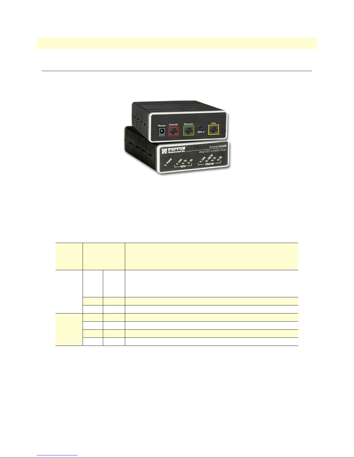
Front Panel Status LEDs
The IpRocketLink routers have all status LEDs on the front panel of the unit, and all electrical connections are
located on the rear panel.
Figure 1. Model 3201
The status LEDs from left to right are (see table 3 for LED descriptions):
• Power
• WAN Link, Tx, and Rx
• Ethernet Link, 100M, Tx, and Rx
Table 3. Status LED descriptions
Power Yellow
WAN
(DSL)
Ethernet Link Yellow
Link Yellow
TX Yellow
RX Yellow
100M Yellow
TX Yellow
RX Yellow
ON
indicates that power is applied.
2 Hz flash
1 Hz flash
8 Hz flash
Solid yellow:
2 Hz flash:
8 Hz flash:
No indication:
Flashing:
Flashing:
On:
On:
Flashing:
Flashing:
occurs during POST
occurs for non-fatal error.
on all LEDs for fatal POST outcome or critical error.
connected
training
DSL error
no signal detected.
when transmitting data from the unit to the WAN.
when receiving data from the WAN to the unit.
Ethernet is linked.
100 Mbps Ethernet is selected.
when data is transmitted from the unit to the LAN.
when data is received from the LAN.
Rear panel connectors and switches
On the rear panel from left to right are the following:
• Power input connector
• Console Port
• Ethernet connector
• MDI-X switch
• Line connector
Off
indicates that no power is applied.
14 Front Panel Status LEDs
Page 17
Model 3201 G.SHDSL Integrated Access Device User Guide 1 • General Information
Power input connector
The router modem comes with an AC or DC power supply. (see “Power and Power Supply Specifications” on
page 113)
• The power connection to the router modem is a 2.5 mm barrel receptacle with the center conductor posi-
tive (see figure 2).
5 VDC
Figure 2. Power connection barrel receptacle 5 VDC diagram
External AC universal power supply
For additonal specifications, see “Power and Power Supply Specifications” on page 113.
• Output from power supply: 5 VDC, 1 A
• Input to power supply: universal input 100–240 VAC 50/60 Hz 0.3A
An approved external power supply that incorporates a disconnect device must be used and positioned within easy reach of
the operator’s position.
Connect the equipment to a 5 VDC source that is electrically isolated from the AC source. The 5 VDC source is to be reliably
connected to earth.
External 48 VDC power supply
Refer to see “Power and Power Supply Specifications” on page 113 for additonal specifications.
• Input
- Rated voltage: 36–60 VDC
- Rated current: 0.25 A DC
- 3-pin locking connector, 3.5 mm pitch
- Transient over-voltage protection, 100VDC at 2 ms
• Output
- Rated voltage: 5 VDC ± 5%, 5W
- Rated current; 1 A DC
- 6-inch cable terminated with 2.5 mm barrel plug, center positive
Connect the equipment to a 30–60 VDC source that is electrically isolated from the AC source. The 30–60 VDC source is to
be reliably connected to earth.
Front Panel Status LEDs 15
Page 18
1 • General Information Model 3201 G.SHDSL Integrated Access Device User Guide
Console port (outlined in red)
The unshielded RJ-45 RS-232 console DCE port (EIA-561) with the pin-out listed in the following table:
Pin No. Signal Direction Signal Name
1 Out DSR
2 Out CD
3 In DTR
4 — Signal Ground
5 Out RD
6 In TD
7 Out CTS
8 In RTS
Ethernet port (outlined in green)
Shielded RJ-45 10Base-T/100Base-TX Ethernet port using pins 1,2,3, & 6. See MDI-X switch for hub or transceiver configuration.The following table defines conditions that occur when the MDI-X switch is in the out position.
Pin No. Signal Direction Signal Name
1 Output TX+
2 Output TX3 Input RX+
4 — —
5 — —
6 Input RX7 — —
8 — —
MDI-X
The MDI-X push switch operates as follows:
• When in the default out position, the Ethernet circuitry takes on a straight-through MDI configuration and
functions as a transceiver. It will connect directly to a hub.
• When in the in position, the Ethernet circuitry is configured in cross-over MDI-X mode so that a straight-
through cable can connect the Model 3201 DSL modem’s Ethernet port directly to a PC’s NIC card.
Line port (outlined in yellow)
The RJ-11/4 DSL line port uses pins 2 and 3 of the RJ-11 port.
Pin No. Signal Name
1 —
2 In/Out-A
3 In/Out-B
4 —
16 Front Panel Status LEDs
Page 19

Chapter 2 Product Overview
Chapter contents
Product Overview..................................................................................................................................................18
Applications Overview ....................................................................................................................................18
17
Page 20

2 • Product Overview Model 3201 G.SHDSL Integrated Access Device User Guide
Product Overview
The Model 3201 modem operates as a bridge or a router and has two ports for communication:
• The Ethernet port—Connects to the LAN side of the connection
• The Line port—Provides the G.SHDSL transmission connection between the CPE and CO DSL modem
The modem provides all layer 2 and layer 3 protocols required for end-to-end-link communication.
When configuring the 3201, questions must be answered so the 3201 functions as desired. For example, when
a router or bridge module needs to be activated, some questions would be:
• Is a default gateway required?
• Which encapsulation technique is best for this application: PPPoA, Frame Relay, PPPoE or another?
These decisions can be made and implemented more easily if the Model 3201’s fundamental architecture is
understood. Also, while configuring the Model 3201 via a browser using the built-in HTTP server is very intuitive, an understanding of the architecture is essential when using the command-line interface (CLI) commands.
The fundamental building blocks comprise a router or bridge, interfaces, and transports. The router and bridge
each have interfaces. A transport provides the path between an interface and an external connection. For example, the Ethernet transport attaches to an Internet Protocol (IP) interface. A transport consists of layer 2 and
everything below it. Creating a transport and attaching it to a bridge or router’s interface enables data to be
bridged or routed. The supported transports are PPPoA, PPPoE, Frame Relay, RFC 1483 (Multiprotocol
Encapsulation over ATM AAL5), IPoA, PPPoH, and Ethernet.
Configuring an interface and transport for the router or bridge requires naming the interface and transport before
attaching them. When using the built-in HTTP server web browser, this is done automatically. But when configuring the Model 3201 via CLI commands through the RS-232 control port, it must be done manually.
Model 3201 modems can connect over an ATM PVC or HDLC transport.
The PVC requires the configuration of the virtual path identifier (VPI) and virtual circuit identifier (VCI). The
VPI can be any integer between 0–4095 inclusive. The general rule for the VCI is an integer between 1–65,535
inclusive. Examples in this manual use a VCI of 600 or above. The main restriction in choosing a VCI is that
VCIs below 32 are reserved for such predefined functions as ILMI. The VCI values of 600 and above used in
this manual are also above the range used by many signaling implementations for SVCs.
The HDLC is a packet-based transmission across the DSL Link.
Several ATM connections are offered to address a variety of user applications. Although they all use RFC1483
as the transport mechanism between the two 3201 modems, WAN services may use different PPP applications,
such as PPPoE routed, PPPoA routed, or PPPoA bridged. Each one has its advantages and disadvantages.
Applications Overview
The Model 3201 is used for bridged or routed applications.
Note In bridged applications the 3201 modem functions transparently on layer 2 to
provide MAC level bridging for Ethernet networks. The bridging is between
Ethernet and the DSL link between the two 3201 modems. The devices
attached to each 3201 are on the same subnet. The number of attached devices
and the size of the filter table are configurable. No IP address is necessary unless
18 Product Overview
Page 21
Model 3201 G.SHDSL Integrated Access Device User Guide 2 • Product Overview
the administrator desires management through a web browser. Then an IP
address is necessary for the administrator to access the 3201 modem.
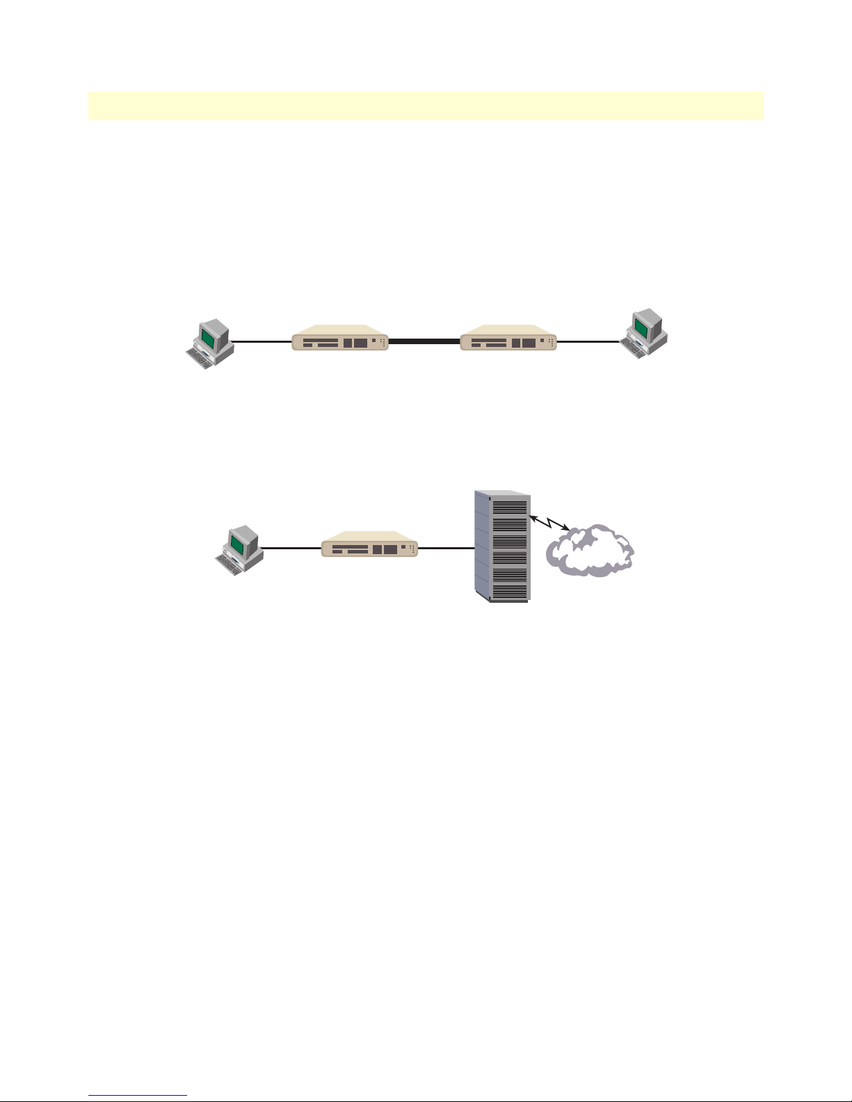
In a typical bridged configuration, the DSL bridge is transparent to the network. It bridges the DSL line to
the Ethernet line, making both sides appear as a single subnet. However, it may still be beneficial to provide an
IP address to the DSL modem for management. In the bridged configuration it is not necessary for the Ethernet port to have an IP address.
DSL
Modem
Subnet 1 Subnet 1
DSL
DSL
Modem
Figure 3. Bridged Application
In a typical routed configuration, the DSL router is treated as a separate device on the network that receives
packets from the PC and DSLAM. The Ethernet and DSL networks are configured as separate IP subnets. The
PC must have the DSL router set up as its default gateway.
DSL
Modem
Subnet 1
Subnet 2
DSLAM
Internet
Figure 4. Routed Application
Model 3201 applications are divided as follows:
• Connecting two stand-alone Model 3201 Bridge/Routers back-to-back using PPPoH Bridged or PPPoH
Routed. PPPoH Bridged can be considered as Ethernet extension since the same logical LAN exists at both
ends of the 3201s and only bridging is required. PPPoH is network extension in the more general sense
since a different logical network is on each end of the 3201s.
• Connecting the Model 3201 bridge/routers as a CPE device to a DSLAM. They can be configured for
bridged or routed mode.
The bridged modes commonly used to connect to a DSLAM are
–
– The routed modes are
RFC1483, HDLC
For more information about router modem applications, refer to Chapter 4, “Basic Application Configurations” on page 27 and Chapter 5, “Specialized Configurations” on page 79.
Product Overview 19
(PPPoH),
PPPoA, IPoA
RFC1483, HDLC
and
PPPoE
.
(PPPoH), and
PPPoA
.
Page 22

2 • Product Overview Model 3201 G.SHDSL Integrated Access Device User Guide
20 Product Overview
Page 23

Chapter 3 Quick Start Installation
Chapter contents
Hardware installation ............................................................................................................................................22
What you will need .........................................................................................................................................22
Identify the connectors and attach the cables ..................................................................................................22
IP address Quick Start modification ................................................................................................................23
Router/Bridge Status LEDs .......................................................................................................................24
Web Operation and Configuration .................................................................................................................24
PC Configuration .....................................................................................................................................24
Web Browser .............................................................................................................................................24
21
Page 24

3 • Quick Start Installation Model 3201 G.SHDSL Integrated Access Device User Guide
Hardware installation
If you are already familiar with Model 3201/3241 Router Modem installation and configuration, this chapter
will enable you to finsh the job quickly. Installation consists of the following:
• Preparing for the installation (see section “What you will need”)
• Hooking up cables, verifying that the unit will power up, and running a HyperTerminal session (see section
“Identify the connectors and attach the cables”)
• Changing the IP address from the factory default setting (see section “IP address Quick Start modification”
on page 23)
• Launching a web browser in preparation for configuring the modem (see “Web Operation and Configura-
tion” on page 24)
What you will need
• Model 3201 or 3241 G.SHDSL Router Modem
• External power supply for Model 3201 or 3241
• Ethernet cable with RJ45 plugs on each end (included with router modem)
• DB9-RJ45 Adapter (included with router modem)
• RJ45/RJ45 straight-through cable for connecting to control port (included with router modem)
• PC computer with HyperTerminal or equivalent VT-100 emulation program, or an ASCII (“dumb”) terminal.
Identify the connectors and attach the cables
All connectors are on the rear panel of the DiamondLink with the exception of the power connection. The
Console port is Red, the Ethernet port is Green, and the Line is Yellow.
Do the following:
1. Connect the DB9-RJ45 adapter to the DB-9 serial port on the PC or dumb terminal. Use the RJ45-RJ45
straight-through cable between the adapter and the red marked RJ45 port on the modem.
2. Do NOT connect the router modem to the Ethernet LAN now.
3. On the PC, start a HyperTerminal session at 9600 bps, 8 data bits, 1 stop bit, and no parity.
4. Power up the router modem.
5. Type “superuser” for Login:, and press Enter.
6. Then type “superuser” for the password, press Enter.
22 Hardware installation
Page 25

Model 3201 G.SHDSL Integrated Access Device User Guide 3 • Quick Start Installation
7. A message will display, “Login Successful.” By typing the character “?”, all the commands will be dis-
played. Any commands parameters may be seen by entering the command followed by a space and a question mark.
→
ethernet ?
add
delete
set
show
list
clear
[The following parameters appear]
IP address Quick Start modification
The first parameter to change is the IP address from the default IP address of 192.168.200.10 (for the CP
units) or 192.168.200.11 (for CO units) to your selected IP address. Follow these steps. Comments are in
brackets […].
→
ip list interfaces <enter>
IP Interfaces:
ID | Name | IP Address | DHCP | Transport
-------|---------------|------------------|-------------|----------------- 1 | ip1 | 192.168.200.10 | disabled | <bridge>
---------------------------------------------------------------------------
→
ip set interface ip1 ipaddress 10.10.10.5 255.255.255.0
address in this example is for illustrative purposes only.]
→
ip list interfaces <enter>
→
system config save <enter>
[lists the characteristics of the different interfaces]
[Sets the new IP address which you have selected. The IP
[To see if the change in IP address is correct]
[To save the new IP address in flash memory.]
Wait for configuration saved message
Saving configuration
→
Configuration saved.
<enter>
→
The IP address has now been successfully changed.
Hardware installation 23
Page 26
3 • Quick Start Installation Model 3201 G.SHDSL Integrated Access Device User Guide
Router/Bridge Status LEDs
The LEDs indicate the status of power, the WAN (DSL) inter-modem link, and the Ethernet connection.
Note When extinguished, the LED indicators are clear; when lit, they shine
a brilliant yellow.
Power Yellow
WAN
(DSL)
Ethernet Link Yellow
Link Yellow
TX Yellow
RX Yellow
100M Yellow
TX Yellow
RX Yellow
ON
indicates that power is applied.
off
indicates that no power is applied.
2 Hz flash
1 Hz flash
8 Hz flash
Solid yellow:
2 Hz flash:
8 Hz flash:
No indication:
Flashing:
Flashing:
On:
On:
Flashing:
Flashing:
occurs during POST
occurs for non-fatal error.
on all LEDs for fatal POST outcome or critical error.
connected
training
DSL error
no signal detected.
when transmitting data from the unit to the WAN.
when receiving data from the WAN to the unit.
Ethernet is linked.
100 Mbps Ethernet is selected.
when data is transmitted from the unit to the LAN.
when data is received from the LAN.
Web Operation and Configuration
Now that the IP address has been configured for your application, you can complete the configuration using
any standard web browser.
PC Configuration
In order to connect the PC to the Ethernet LAN to communicate with the Model 3201, the PC’s IP address
should be on the same subnet as the modem.
Connect a straight-through Ethernet cable between the PC’s NIC or PCMCIA Ethernet card and an Ethernet
hub or switch.
Web Browser
Do the following:
1. Launch a standard web browser such as Netscape Communicator or Internet Explorer (IE).
2. Enter the 3201’s IP address into the URL or Address field of the browser.
24 Hardware installation
Page 27
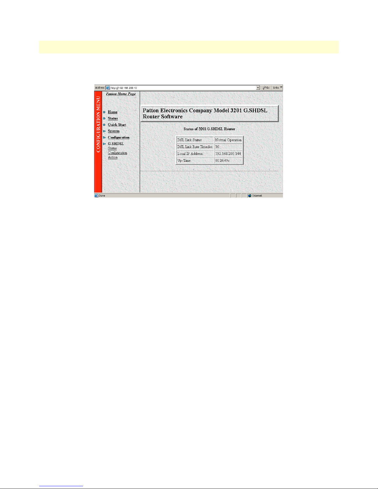
Model 3201 G.SHDSL Integrated Access Device User Guide 3 • Quick Start Installation
The Model 3201 home page displays (see Figure 5).
Figure 5. Model 3201 home page
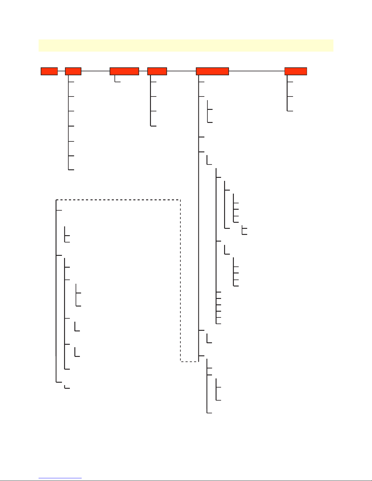
The Model 3201/3241 menu structure is shown in figure 6 on page 26.
Hardware installation 25
Page 28
3 • Quick Start Installation Model 3201 G.SHDSL Integrated Access Device User Guide
Home
Status
WAN Settings
> WAN Connections
LAN Settings
> LAN Connection
Ethernet
> Ethernet Port Configuration
IP Address Settings
> WAN Connections
DNS Client Settings
> DNS Client
DHCP Server Settings
> DHCP Server
Show Statistics (for each defined interface)
> [Unique name for each interface]
DNS client
> DNS Client
DNS relay
> DNS Relay
Disabled
Enabled
> DNS: enable relay
Security
> Security Interface Configuration
Add Interface
> Firewall: Add Interface
Advanced NAT Configuration*
> Advanced NAT Configuration: [name of interface]
Add Global Address Pool
> Firewall Add Global Address Pool: [name of interface]
Add Reserved Mapping
> Firewall Add Reserved Mapping: [name of interface]
Firewall Policy Configuration
> Firewall Policy Configuration
New Policy
> Firewall Add Policy
Firewall Trigger Configuration*
> Firewall Trigger Configuration
New Trigger
> Firewall Add Trigger
Configure Intrusion Detection*
> Firewall Configure Intrusion Detection
Ports
Ethernet
> Ethernet Port Configuration
Quick Start System
Quick Start
Error Log
> Error Log
Remote Access
> Remote Access
Upgrade
> Firmware Upgrade
Restart
> Reset Router
Configuration
Save Configuration
> Save Configuration
Authentication
> Authentication
Edit user
> Authentication: edit user [name of user]
Create a new user
> Authentication: create user
LAN connection
> LAN connection
WAN connections
> WAN Connections
Create a new service
> WAN connection: create service
RFC1483 Routed
> WAN connection: RFC 1483 routed
Edit* (via WAN connections web page)
> WAN connection: edit`rfc1483-0’
Edit `Service’
Edit `RFC1843’
Edit `Atm Channel’
Edit `Ip Interface’
Edit `Rip Versions’
Edit `Tcp Mss Clamp’
RFC1483 Bridged
> WAN connection: RFC 1483 bridged
Edit*
> WAN connection: edit `rfc1483-0’
Edit `Service’
Edit `RFC1483’
Edit `Atm Channel’
Edit `Bridge Interface’
PPPoA Routed
PPPoA Bridged
IPoA Routed
PPPoE Routed
PPPoH Routed
PPPoH Bridged
IP routes
> Edit routes
Create new Ip V4 Route
> Create Ip V4Route
DHCP server
> DHCP server
Disabled
DHCP Server
>DHCP: enable server
Advanced Options
> Edit Dhcp Server
Help
> DHCP Server Configuration
DHCP Relay Agent
> DHCP: enable relay agent
G.SHDSL
Status
> G.SHDSL Status
Configuration
> G.SHDSL Attributes
Action
> G.SHDSL Actions
26 Hardware installation
Figure 6. Model 3201/3241 Menu Structure
Page 29

Chapter 4 Basic Application Configurations
Chapter contents
Introduction..........................................................................................................................................................30
Two stand-alone units directly connected..............................................................................................................31
Ethernet Extension (HDLC - PPPoH Bridged) ..............................................................................................31
Network Extension (HDLC—PPPoH Routed) ..............................................................................................34
DSLAM Connections with remote CPE units.......................................................................................................38
Bridged application configurations to a DSLAM ............................................................................................38
RFC 1483 Bridged Configuration. ............................................................................................................38
PPPoH Bridged Configuration .................................................................................................................41
PPPoA Bridged (RFC 2364) Configuration ..............................................................................................44
Routed application configurations to a DSLAM .............................................................................................46
RFC 1483 Routed .....................................................................................................................................46
PPPoH Routed .........................................................................................................................................52
PPPoA Routed (RFC 2364) ......................................................................................................................56
IPoA Routed (RFC 1577) ........................................................................................................................67
27
Page 30
4 • Basic Application Configurations Model 3201 G.SHDSL Integrated Access Device User Guide
Introduction
The basic applications are divided according to whether the application is bridged or routed.
The bridged applications are RFC 1483 Bridged, PPPoA Bridged, and HDLC Bridged.
The routed applications are RFC 1483, PPPoA, IPoA, PPPoE, and HDLC.
Another way of organizing the applications is according to the type of encapsulation: PPP, RFC 1483, or Frame
Relay. PPP encapsulation is available as PPPoA bridged or routed and PPPoE. RFC 1483 and Frame Relay can
be configured for bridged and routed connections.
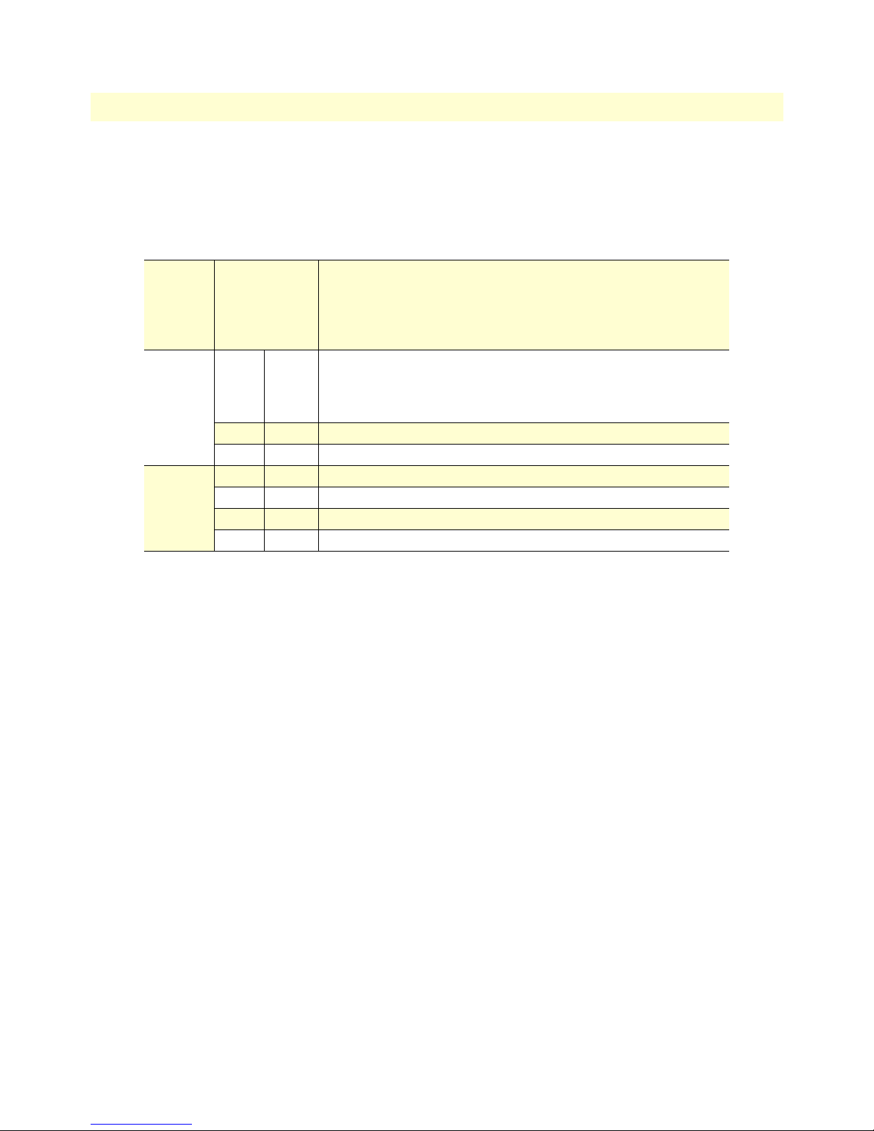
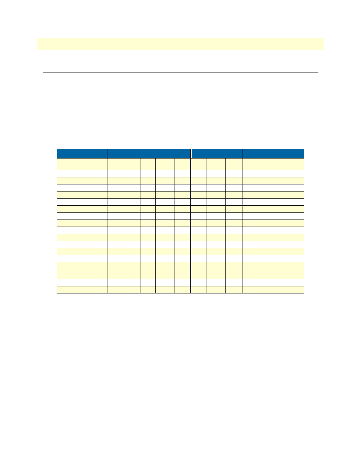
The following table shows the parameters that can be configured via the HTTP server using a web browser.
Routed WAN Services Bridged WAN Services
Web Page Parameter RFC
Description X X X X X X X X
VPI X X X X X X default = 0
VCI X X X X X X default = 35
Encapsulation LLC VcMux LLC LLC or VcMux
Use DHCP X X X
WAN IP address X X X default mask = 255.255.255.0
LLC header X
HDLC header ON ON
No authentication X X X
PAP X X X
CHAP X X X
User Name X X X
Password X X X
WAN IP address
(Client modem for PPPoA)
Access Concentrator X
HDLC Encapsulation X X
PPPoA IPoA PPPoE PPPoH RFC
1483
X
(0.0.0.0)
for client
PPPoA PPPoH Comments
1483
Local IP Mask = 255.255.255.0
28 Introduction
Page 31

Model 3201 G.SHDSL Integrated Access Device User Guide 4 • Basic Application Configurations
Two stand-alone units directly connected
Ethernet Extension (HDLC - PPPoH Bridged)
Model 3201 (Remote) Configuration Steps (PPPoH Bridged)
From the command line interface (CLI) via the RS-232 control port,
→
ip list interfaces
One IP interface is called ip1 with an IP address of 192.168.1.1
Let’s change the IP address so it is in the same subnet as both PCs. For example, to 192.168.100.2
→
ip set interface ip1 ipaddress 192.168.100.2 255.255.255.0
1. Now you can bring up the web-page management system on your browser by entering the IP address of
the 3201.
2. On the Menu, go to
Configuration, then to WAN Connections. Delete the factory default WAN services already
defined.
Click on
Create a new service in the main window, select PPPoH_Bridged and click on the Configure button.
3. In the Description field, enter the description you wish. In this example, it is called PPPoH Bridged.
Two stand-alone units directly connected 29
Page 32

4 • Basic Application Configurations Model 3201 G.SHDSL Integrated Access Device User Guide
Verify the settings to be:
– Interface = 1
– LLC header mode = dialout
– LLC header mode = off
– HDLC header mode = on
– No authentication
– Leave User name and Password blank.
Click on
4. Go to
Apply.
G.SHDSL in the Configuration Menu, then the submenu Configuration.
30 Two stand-alone units directly connected
Page 33

Model 3201 G.SHDSL Integrated Access Device User Guide 4 • Basic Application Configurations
Change Terminal Type to Central and Interface Type to hdlc. Click on the Configure button.
In the Action submenu under G.SHDSL, change Action to
Return to Action, select
Start and click on Action.
Deactivate, then click on Action.
Model 3201 (Central) Configuration Steps (PPPoH Bridged)
See the Web page images for the Remote Model 3201 configuration above.
From the command line interface (CLI) via the RS-232 control port,
→
ip list interfaces
One IP interface is called ip1 with an IP address of 192.168.1.1
Change the IP address so it is in the same subnet as both PCs. For example, to 192.168.100.3
→
ip set interface ip1 ipaddress 192.168.100.3 255.255.255.0
1. Now you can bring up the web-page management system on your browser by entering the IP address of
the 3201.
2. On the Menu, go to
Configuration, then to WAN Connections. Delete the factory default WAN services already
defined.
Click on
In the
Create a new service in the main window, select PPPoH_Bridged and click on the Configure button.
Description field, enter the description you wish. In this example, it is called PPPoH Bridged.
Verify the settings to be:
– Interface = 1
– LLC header mode = dialout
Two stand-alone units directly connected 31
Page 34

4 • Basic Application Configurations Model 3201 G.SHDSL Integrated Access Device User Guide
– LLC header mode = off
– HDLC header mode = on
– No authentication
– Leave User name and Password blank.
Click on
3. Go to
Apply.
G.SHDSL in the Configuration Menu, then the submenu Configuration.
Leave Terminal Type as Remote.
Change Interface Type to
hdlc. Click on the Configure button.
In the Action submenu under G.SHDSL, change Action to
Return to Action, select
Start and click on Action.
Network Extension (HDLC—PPPoH Routed)
Deactivate, then click on Action.
Model 3201 (Remote) Configuration Steps (PPPoH Routed)
From the command line interface (CLI) via the RS-232 control port,
→
ip list interfaces
One IP interface was called ip1 with an IP address of 192.168.1.1 Change it to an IP address which is in the
same subnet as the Desktop PC. For example, to 192.168.100.2. The default IP mask is 255.255.255.0.
→
ip set interface ip1 ipaddress 192.168.100.2 255.255.255.0
32 Two stand-alone units directly connected
Page 35

Model 3201 G.SHDSL Integrated Access Device User Guide 4 • Basic Application Configurations
1. Now you can bring up the web-page management system on your browser by entering the IP address of
the 3201.
Click on
is “hdlc.” If changed, then click on
Click on
2. On the Menu, go to
G.SHDSL in the Configuration Menu > Configuration > verify that Terminal Type is Central and Interface Type
Configure.
Action > Select deactivate for Action > Click on the Action button.
Configuration, then to WAN Connections
Delete both default WAN services already defined.
Click on
Create a new service in the main window, select PPPoH_Routed and click on the Configure button.
In the Description field, enter the description you wish. In this example, it is called PPPoH Routed.
– Description: PPPoH Routed
– Interface: 1
– WAN IP address: 192.168.164.2
– LLC Header Mode: off
– HDLC Header Mode: ON
– No authentication
– Username: [blank]
– Password: [blank]
Two stand-alone units directly connected 33
Page 36

4 • Basic Application Configurations Model 3201 G.SHDSL Integrated Access Device User Guide
Click on Configure.
3. Go to
Configuration Menu > Configuration > WAN connections > Edit (for PPPoH Routed service) > Edit ‘IP Interface’ > Ipaddr: [enter
the WAN IP Address, in this example = 192.168.164.2] > Click on
Change.
34 Two stand-alone units directly connected
Page 37

Model 3201 G.SHDSL Integrated Access Device User Guide 4 • Basic Application Configurations
4. Configuration Menu > Configuration > IP Routes > Click on Create new Ip V4 Route > Create the gateway to the remote
3201 by entering the WAN IP address of the remote 3201, in this example, enter 192.168.164.3 in the
Gateway field > OK
The other fields should be:
– Destination: 0.0.0.0
– Gateway: 192.168.164.3 [already configured in first part of step 4).]
– Mask: 0.0.0.0
– Cost: 1
– Interface: [blank]
Two stand-alone units directly connected 35
Page 38

4 • Basic Application Configurations Model 3201 G.SHDSL Integrated Access Device User Guide
5. Go to G.SHDSL in the Configuration Menu, then the submenu Status. The Modem State should be
“deactivated.” (If not, go to the Action and change it to deactivate.)
Then in the Action submenu under G.SHDSL, change Action to Start, then click on
Action.
Model 3201 (Central) Configuration Steps (PPPoH Routed)
See the web pages for the desktop above. Some parametric values are different although the process is the same.
From the command line interface (CLI) via the RS-232 control port,
→
ip list interfaces
→
ip clear routes
→
pppoh clear transports
→
ethernet add transport eth1 ethernet
One IP interface was called ip1 with an IP address of 192.168.1.1
Change the IP address so it is in the same subnet as the laptop PC. The laptop’s IP address is
192.168.172.229, so in this example, change the IP address of the 3201 to 192.168.172.3. The default IP
mask is 255.255.255.0.
→
ip set interface ip1 ipaddress 192.168.172.3 255.255.255.0
1. Now you can bring up the web-page management system on your browser by entering the IP address of
the 3201.
36 Two stand-alone units directly connected
Page 39

Model 3201 G.SHDSL Integrated Access Device User Guide 4 • Basic Application Configurations
Click on G.SHDSL in the Configuration Menu > Configuration > verify that Terminal Type is remote and Interface Type
is “hdlc.” If changed, then click on
Configure.
Click on
2. On the Menu, go to
Action > Select deactivate for Action > Click on the Action button.
Configuration, then to WAN Connections.
Delete both default WAN services already defined.
Click on
Create a new service in the main window, select PPPoH_Routed and click on the Configure button.
In the Description field, enter the description you wish. In this example, it is called PPPoH Routed.
Description:PPPoH Routed
– Interface:1
– WAN IP address: 192.168.164.3
– LLC Header Mode:off
– HDLC Header Mode:ON
– No authentication
– Username:[blank]
– Password:[blank]
Click on
3. Go to
the WAN IP Address, in this example = 192.168.164.3] > Click on
Configure.
Configuration Menu > Configuration > WAN connections > Edit (for PPPoH Routed service) > Edit ‘IP Interface’ > Ipaddr: [enter
Change.
4.
Configuration Menu > Configuration > IP Routes > Click on Create new Ip V4 Route > Create the gateway to the remote
3201 by entering the WAN IP address of the remote 3201, in this example, enter 192.168.164.2 in the
Gateway field > OK
The other fields should be:
– Destination:0.0.0.0
– Gateway:192.168.164.2 [already changed in the first part of step 5).]
– Mask:0.0.0.0
Two stand-alone units directly connected 37
Page 40

4 • Basic Application Configurations Model 3201 G.SHDSL Integrated Access Device User Guide
– Cost:1
– Interface:[blank]
5. Go to
G.SHDSL in the Configuration Menu, then the submenu Status. The Modem State should be “deacti-
vated.” (If not, go to the Action and change it to deactivate.)
Then in the Action submenu under G.SHDSL, change Action to Start, then click on
Action.
DSLAM Connections with remote CPE units
Bridged application configurations to a DSLAM
Three bridged services are offered, RFC 1483 Bridged, PPPoA Bridged, and HDLC Bridged.
The configurations show a desktop on one end and a laptop on the other. The laptop and its Model 3201
would be replaced with a DSLAM.
RFC 1483 Bridged Configuration.
No additional IP addresses are needed other than the IP address chosen earlier. In fact, if you are configuring and
managing the model 3201 only from the CLI (Command Line Interface), an IP address is not needed at all. The
limitation of no IP address precludes the user from doing web management of the 3201 since management is
done via the Ethernet port.
As in the PPPoA Bridged application, both sides of the RFC 183 bridged connection are on the same subnet.
38 DSLAM Connections with remote CPE units
Page 41

Model 3201 G.SHDSL Integrated Access Device User Guide 4 • Basic Application Configurations
Model 3201 (Remote) Configuration Steps (RFC 1483 Bridged)
From the command line interface (CLI) via the RS-232 control port,
→
ip list interfaces
One IP interface is called ip1 with an IP address of 192.168.1.1
Change the IP address so it is in the same subnet as both PCs. For example, to 192.168.100.2
→
ip set interface ip1 ipaddress 192.168.100.2 255.255.255.0
1. Now you can bring up the web-page management system on your browser by entering the IP address of
the 3201.
2. On the Menu, go to Configuration, then to WAN Connections. Delete the factory default WAN services
already defined.
Click on
Create a new service in the main window, select RFC_1483_Bridged and click on the Configure button.
In the Description field, enter the description you wish. In this example, it is called RFC 1483 B.
Leave VCI as 35 and Encapsulation Method as LLC/SNAP. Then click on
3. Go to
G.SHDSL in the Configuration Menu, then the submenu Configuration.
Apply.
DSLAM Connections with remote CPE units 39
Page 42

4 • Basic Application Configurations Model 3201 G.SHDSL Integrated Access Device User Guide
Change Terminal Type to Central and Interface Type to atm. Click on the Configure button.
In the Action submenu under G.SHDSL, change Action to
Return to Action, select
Start and click on Action.
Deactivate, then click on Action.
Model 3201 (Central) Configuration Steps (RFC 1483 Bridged)
Although the some parametric values may vary from the desktop’s Model 3201, the process is identical.
From the command line interface (CLI) via the RS-232 control port,
→
ip list interfaces
One IP interface is called ip1 with an IP address of 192.168.1.1
Change the IP address so it is in the same subnet as both PCs. For example, to 192.168.100.3
→
ip set interface ip1 ipaddress 192.168.100.3 255.255.255.0
1. Now you can bring up the web-page management system on your browser by entering the IP address of
the 3201.
2. On the Menu, go to Configuration, then to WAN Connections. Delete the factory default WAN services
already defined.
Click on
Create a new service in the main window, select RFC_1483_Bridged and click on the Configure button.
In the Description field, enter the description you wish. In this example, it is called RFC 1483 B.
Leave VCI as 35 and Encapsulation Method as LLC/SNAP. Then click on
Apply.
3. Go to G.SHDSL in the Configuration Menu, then the submenu Configuration.
Leave Terminal Type as Remote, but change Interface Type to atm. Click on the
40 DSLAM Connections with remote CPE units
Configure button.
Page 43

Model 3201 G.SHDSL Integrated Access Device User Guide 4 • Basic Application Configurations
In the Action submenu under G.SHDSL, change Action to Deactivate, then click on Action.
Return to Action, select Start and click on Action.
PPPoH Bridged Configuration
Model 3201 (Remote) Configuration Steps (PPPoH Bridged)
From the command line interface (CLI) via the RS-232 control port,
→
ip list interfaces
One IP interface is called ip1 with an IP address of 192.168.1.1 Change the IP address so it is in the same subnet as both PCs. For example, to 192.168.100.2
→
ip set interface ip1 ipaddress 192.168.100.2 255.255.255.0
1. Now you can bring up the web-page management system on your browser by entering the IP address of
the 3201.
2. On the Menu, go to
Configuration, then to WAN Connections. Delete the factory default WAN services
already defined.
Click on
DSLAM Connections with remote CPE units 41
Create a new service in the main window, select PPPoH_Bridged and click on the Configure button.
Page 44

4 • Basic Application Configurations Model 3201 G.SHDSL Integrated Access Device User Guide
In the Description field, enter the description you wish. In this example, it is called PPPoH Bridged.
– Interface = 1
– LLC header mode = dialout
– LLC header mode = off
– HDLC header mode = on
– No authenticaion
– Leave User name and Password blank.
– Click on
3. Go to
– Change Terminal Type to Central and Interface Type to hdlc. Click on the
– In the Action submenu under G.SHDSL, change Action to Deactivate, then click on
– Return to Action, select
42 DSLAM Connections with remote CPE units
Apply.
G.SHDSL in the Configuration Menu, then the submenu Configuration.
Configure button.
Action.
Start and click on Action.
Page 45

Model 3201 G.SHDSL Integrated Access Device User Guide 4 • Basic Application Configurations
Model 3201 (Central) Configuration Steps (PPPoH Bridged)
From the command line interface (CLI) via the RS-232 control port,
→
ip list interfaces
One IP interface is called ip1 with an IP address of 192.168.1.1
Change the IP address so it is in the same subnet as both PCs. For example, to 192.168.100.3
→
ip set interface ip1 ipaddress 192.168.100.3 255.255.255.0
1. Now you can bring up the web-page management system on your browser by entering the IP address of
the 3201.
2. On the Menu, go to Configuration, then to WAN Connections. Delete the factory default WAN services
already defined.
Click on
Create a new service in the main window, select PPPoH_Bridged and click on the Configure button.
In the Description field, enter the description you wish. In this example, it is called PPPoH Bridged.
– Interface = 1
– LLC header mode = dialout
– LLC header mode = off
– HDLC header mode = on
– No authenticaion
– Leave User name and Password blank.
Click on
Apply.
3. Go to G.SHDSL in the Configuration Menu, then the submenu Configuration.
Leave Terminal Type as Remote.
Change Interface Type to hdlc. Click on the Configure button.
In the Action submenu under G.SHDSL, change Action to Deactivate, then click on
Return to Action, select Start and click on
Action.
Action.
DSLAM Connections with remote CPE units 43
Page 46

4 • Basic Application Configurations Model 3201 G.SHDSL Integrated Access Device User Guide
PPPoA Bridged (RFC 2364) Configuration
The user data for transmission is in the form of IP packets but encapsulated in a PPP packet, transmitted and
received through a PPP session to the connection. The PPP packets are encapsulated according to RFC 2364 for
transmission over the ATM link. The packets are de-encapsulated on the receive side so that the IP data can be
delivered to the end user.
Model 3201 (Remote) Configuration Steps (PPPoA Bridged)
From the command line interface (CLI) via the RS-232 control port,
→
ip list interfaces
One IP interface is called ip1 with an IP address of 192.168.1.1
Change the IP address so it is in the same subnet as both PCs. For example, to 192.168.100.2
→
ip set interface ip1 ipaddress 192.168.100.2 255.255.255.0
1. Now you can bring up the web-page management system on your browser by entering the IP address of
the 3201.
2. On the Menu, go to Configuration, then to WAN Connections. Delete the factory default WAN services
already defined.
Click on
Create a new service in the main window, select PPPoA_Bridged and click on the Configure button.
In the Description field, enter the description you wish. In this example, it is called PPPoA Bridged.
– VPI = 0
44 DSLAM Connections with remote CPE units
Page 47

Model 3201 G.SHDSL Integrated Access Device User Guide 4 • Basic Application Configurations
– VCI = 300
– LLC header mode = off
– HDLC header mode = off
– No authentication
– Leave User name and Password blank.
Click on
Apply.
3. Go to G.SHDSL in the Configuration Menu, then the submenu Configuration.
Change Terminal Type to Central and Interface Type to atm. Click on the
In the Action submenu under G.SHDSL, change Action to
Return to Action, select
Start and click on Action.
Deactivate, then click on Action.
Configure button.
Model 3201 (Central)Configuration Steps (PPPoA Bridged)
From the command line interface (CLI) via the RS-232 control port,
→
ip list interfaces
One IP interface is called ip1 with an IP address of 192.168.1.1
Change the IP address so it is in the same subnet as both PCs. For example, to 192.168.100.3
→
ip set interface ip1 ipaddress 192.168.100.3 255.255.255.0
1. Now you can bring up the web-page management system on your browser by entering the IP address of
the 3201.
2. On the Menu, go to Configuration, then to WAN Connections. Delete the factory default WAN services
already defined.
Click on
Create a new service in the main window, select PPPoA_Bridged and click on the Configure button.
In the Description field, enter the description you wish. In this example, it is called PPPoA Bridged.
– VPI = 0
– VCI = 300
– LLC header mode = off
– HDLC header mode = off
– No authentication
– Leave User name and Password blank.
DSLAM Connections with remote CPE units 45
Page 48

4 • Basic Application Configurations Model 3201 G.SHDSL Integrated Access Device User Guide
Click on Apply.
3. Go to G.SHDSL in the Configuration Menu, then the submenu Configuration.
Leave Terminal Type as Remote.
Change Interface Type to atm. Click on the
In the Action submenu under G.SHDSL, change Action to Deactivate, then click on
Return to Action, select
Start and click on Action.
Configure button.
Action.
Routed application configurations to a DSLAM
Five routed WAN services are offered, RFC 1483, PPPoH, IPoA, PPPoA, and PPPoE Routed.
RFC 1483 Routed
RFC 1483 provides the simplest method of connecting end stations over an ATM network. User data in the
form of Ethernet packets is encapsulated into AAL-5 PDUs for transport over ATM. RFC 1483 provides no
authentication and configuration that would be provided by PPP.
Model 3201 (Remote) Configuration Steps (RFC 1483 Routed)
From the command line interface (CLI) via the RS-232 control port,
→
ip list interfaces
One IP interface was called ip1 with an IP address of 192.168.1.1 Change it to an IP address which is in the
same subnet as the Desktop PC. For example, to 192.168.100.2. The default IP mask is 255.255.255.0.
→
ip set interface ip1 ipaddress 192.168.100.2 255.255.255.0
46 DSLAM Connections with remote CPE units
Page 49

Model 3201 G.SHDSL Integrated Access Device User Guide 4 • Basic Application Configurations
1. Now you can bring up the web-page management system on your browser by entering the IP address of
the 3201.
Click on G.SHDSL in the Configuration Menu > Configuration > verify that Terminal Type is Central
and Interface Type is atm. If changed, then click on
Configure.
Click on Action > Select deactivate for Action > Click on the Action button.
2. On the Menu, go to Configuration, then to WAN Connections.
Delete both default WAN services already defined.
Click on
Create a new service in the main window, select RFC 1483 Routed and click on the Configure button.
DSLAM Connections with remote CPE units 47
Page 50

4 • Basic Application Configurations Model 3201 G.SHDSL Integrated Access Device User Guide
In the Description field, enter the description you wish. In this example, it is called RFC 1483 Routed.
Change the configuration parameters to match the following.
Description:RFC 1483 Routed
– VPI:0
– VCI:35
– Encapsulation Method: LLC/SNAP
– WAN IP Address:192.168.164.2
Click on
Configure.
3. Configuration Menu > Configuration > IP Routes > Click on Create new Ip V4 Route > Create the gate-
way to the remote 3201 by entering the WAN IP address of the remote 3201, in this example, enter
192.168.164.3 in the Gateway field > OK
48 DSLAM Connections with remote CPE units
Page 51

Model 3201 G.SHDSL Integrated Access Device User Guide 4 • Basic Application Configurations
The other fields should be:
– Destination:0.0.0.0
– Gateway:192.168.164.3
– Mask:0.0.0.0
– Cost:1
– Interface:[blank]
4. Go to G.SHDSL in the Configuration Menu, then the submenu Status. The Modem State should be
“deactivated.” (If not, go to the Action and change it to deactivate.)
Then in the Action submenu under G.SHDSL, change Action to
Start, then click on Action.
Model 3201 (Central) Configuration Steps (RFC 1483 Routed)
From the command line interface (CLI) via the RS-232 control port,
→
ip list interfaces
→
pppoh clear transports
One IP interface was called ip1 with an IP address of 192.168.1.1
DSLAM Connections with remote CPE units 49
Page 52

4 • Basic Application Configurations Model 3201 G.SHDSL Integrated Access Device User Guide
Change the IP address so it is in the same subnet as the laptop PC. The laptop’s IP address is
192.168.172.229, so in this example, change the IP address of the 3201 to 192.168.172.3. The default IP
mask is 255.255.255.0.
→
ip set interface ip1 ipaddress 192.168.100.2 255.255.255.0
1. Now you can bring up the web-page management system on your browser by entering the IP address of
the 3201.
Click on G.SHDSL in the Configuration Menu > Configuration > verify that Terminal Type is Remote and
Interface Type is atm. If changed, then click on
Configure.
50 DSLAM Connections with remote CPE units
Page 53

Model 3201 G.SHDSL Integrated Access Device User Guide 4 • Basic Application Configurations
Click on Action > Select deactivate for Action > Click on the Action button.
2. On the Menu, go to Configuration, then to WAN Connections.
Delete both default WAN services already defined.
Click on
Create a new service in the main window, select RFC 1483 Routed and click on the Configure button.
In the Description field, enter the description you wish. In this example, it is called RFC 1483 Routed.
Description:RFC 1483 Routed
– VPI:0
– VCI:35
– Encapsulation Method: LLC/SNAP
– WAN IP Address:192.168.164.3
Click on
Configure.
DSLAM Connections with remote CPE units 51
Page 54

4 • Basic Application Configurations Model 3201 G.SHDSL Integrated Access Device User Guide
3. Configuration Menu > Configuration > IP Routes > Click on Create new Ip V4 Route > Create the gate-
way to the remote 3201 by entering the WAN IP address of the remote 3201, in this example, enter
192.168.164.2 in the Gateway field > OK
The other fields should be:
– Destination:0.0.0.0
– Gateway:192.168.164.2
– Mask:0.0.0.0
– Cost:1
– Interface:[blank]
52 DSLAM Connections with remote CPE units
Page 55

Model 3201 G.SHDSL Integrated Access Device User Guide 4 • Basic Application Configurations
4. Go to G.SHDSL in the Configuration Menu, then the submenu Status. The Modem State should be
“deactivated.” (If not, go to the Action and change it to deactivate.)
Then in the Action submenu under G.SHDSL, change Action to Start, then click on Action.
The modems should link up within 30 seconds or so and the link is ready for communication.
PPPoH Routed
Model 3201 (Remote) Configuration Steps (PPPoH Routed)
From the command line interface (CLI) via the RS-232 control port,
→
ip list interfaces
→
ip clear routes
→
pppoh clear transports
DSLAM Connections with remote CPE units 53
Page 56

4 • Basic Application Configurations Model 3201 G.SHDSL Integrated Access Device User Guide
One IP interface was called ip1 with an IP address of 192.168.1.1 Change it to an IP address which is in the
same subnet as the Desktop PC. For example, to 192.168.100.2. The default IP mask is 255.255.255.0.
→
ip set interface ip1 ipaddress 192.168.100.2 255.255.255.0
1. Now you can bring up the web-page management system on your browser by entering the IP address of
the 3201.
Click on G.SHDSL in the Configuration Menu > Configuration > verify that Terminal Type is Central
and Interface Type is hdlc. If changed, then click on
Configure.
Click on Action > Select deactivate for Action > Click on the Action button.
2. On the Menu, go to Configuration, then to WAN Connections
Delete both default WAN services already defined.
Click on
Create a new service in the main window, select PPPoH_Routed and click on the Configure button.
In the Description field, enter the description you wish. In this example, it is called PPPoH Routed.
– Description:PPPoH Routed
– Interface:1
– WAN IP address: 192.168.164.2
– LLC Header Mode:off
– HDLC Header Mode:ON
– No authentication
54 DSLAM Connections with remote CPE units
Page 57

Model 3201 G.SHDSL Integrated Access Device User Guide 4 • Basic Application Configurations
– Username:[blank]
– Password:[blank]
Click on
Configure.
3. Go to Configuration Menu > Configuration > WAN connections > Edit (for PPPoH Routed service) >
Edit ‘IP Interface’ > Ipaddr: [enter the WAN IP Address, in this example = 192.168.164.2] > Click on
Change.
DSLAM Connections with remote CPE units 55
Page 58

4 • Basic Application Configurations Model 3201 G.SHDSL Integrated Access Device User Guide
4. Configuration Menu > Configuration > IP Routes > Click on Create new Ip V4 Route > Create the gate-
way to the remote 3201 by entering the WAN IP address of the remote 3201, in this example, enter
192.168.164.3 in the Gateway field > OK
The other fields should be:
Destination:0.0.0.0
Gateway:192.168.164.3 [already configured in first part of step 5).]
Mask:0.0.0.0
Cost:1
Interface:[blank]
56 DSLAM Connections with remote CPE units
Page 59

Model 3201 G.SHDSL Integrated Access Device User Guide 4 • Basic Application Configurations
5. Go to G.SHDSL in the Configuration Menu, then the submenu Status. The Modem State should be
“deactivated.” (If not, go to the Action and change it to deactivate.)
Then in the Action submenu under G.SHDSL, change Action to Start, then click on
Action.
Model 3201 (Central) Configuration Steps (PPPoH Routed)
From the command line interface (CLI) via the RS-232 control port,
→
ip list interfaces
→
pppoh clear transports
One IP interface was called ip1 with an IP address of 192.168.1.1
Change the IP address so it is in the same subnet as the laptop PC. The laptop’s IP address is
192.168.172.229, so in this example, change the IP address of the 3201 to 192.168.172.3. The default IP
mask is 255.255.255.0.
→
ip set interface ip1 ipaddress 192.168.172.3 255.255.255.0
DSLAM Connections with remote CPE units 57
Page 60

4 • Basic Application Configurations Model 3201 G.SHDSL Integrated Access Device User Guide
1. Now you can bring up the web-page management system on your browser by entering the IP address of
the 3201.
Click on G.SHDSL in the Configuration Menu > Configuration > verify that Terminal Type is Central
and Interface Type is hdlc. If changed, then click on
Configure.
Click on Action > Select deactivate for Action > Click on the
Action button.
2. On the Menu, go to Configuration, then to WAN Connections.
Delete both default WAN services already defined.
Click on
Create a new service in the main window, select PPPoH_Routed and click on the Configure button.
In the Description field, enter the description you wish. In this example, it is called PPPoH Routed.
– Description:PPPoH Routed
– Interface:1
– WAN IP address: 192.168.164.3
– LLC Header Mode:off
– HDLC Header Mode:ON
– No authentication
– Username:[blank]
– Password:[blank]
Click on
Configure.
58 DSLAM Connections with remote CPE units
Page 61

Model 3201 G.SHDSL Integrated Access Device User Guide 4 • Basic Application Configurations
3. Go to Configuration Menu > Configuration > WAN connections > Edit (for PPPoH Routed service) >
Edit ‘IP Interface’ > Ipaddr: [enter the WAN IP Address, in this example = 192.168.164.3] > Click on
Change.
4. Configuration Menu > Configuration > IP Routes > Click on Create new Ip V4 Route > Create the gate-
way to the remote 3201 by entering the WAN IP address of the remote 3201, in this example, enter
192.168.164.2 in the Gateway field > OK
The other fields should be:
– Destination:0.0.0.0
– Gateway:192.168.164.2 [already changed in the first part of step 5).]
– Mask:0.0.0.0
– Cost:1
– Interface:[blank]
5. Go to G.SHDSL in the Configuration Menu, then the submenu Status. The Modem State should be
“deactivated.” (If not, go to the Action and change it to deactivate.)
Then in the Action submenu under G.SHDSL, change Action to Start, then click on
Action.
DSLAM Connections with remote CPE units 59
Page 62

4 • Basic Application Configurations Model 3201 G.SHDSL Integrated Access Device User Guide
PPPoA Routed (RFC 2364)
This routed application is very similar to the PPPoA Bridged application. The user data for transmission is in
the form of IP packets but encapsulated in a PPP packet, transmitted and received through a PPP session to the
connection. The PPP packets are encapsulated according to RFC 2364 for transmission over the ATM link.
The packets are de-encapsulated on the receive side so that the IP data can be delivered to the end user.
The Central (Model 3201) end functions as a local ISP which will authenticate the Remote user (Model
3201). The CPE side, with Remote and 3201-A, may represent a home PC which is connecting to a centralized PPP server (Local and 3201—B).
Since this is a routed application, there are differences to be noted. Referring to the application diagram, three
unique subnets exist. The Ethernet LAN on the 3201 and Remote side, the Ethernet LAN on the 3201 and
Central side, and lastly, the subnet of the ATM’s PVC link between the two modems, 3201-A and 3201-B.
The 3201-B and Local end (the Central side) may also be a DSLAM.
Model 3201 (Remote—Client) Configuration Steps (PPPoA Routed)
1. From the command line interface (CLI) via the RS-232 control port,
→
ip list interfaces
One IP interface was called ip1 with an IP address of 192.168.1.1 Change it to an IP address which is in
the same subnet as the Desktop PC. For example, to 192.168.100.2. The default IP mask is
255.255.255.0.
→
ip set interface ip1 ipaddress 192.168.100.2 255.255.255.0
60 DSLAM Connections with remote CPE units
Page 63

Model 3201 G.SHDSL Integrated Access Device User Guide 4 • Basic Application Configurations
Now you can bring up the web-page management system on your browser by entering the IP address of
the 3201.
Click on G.SHDSL in the Configuration Menu > Configuration > verify that Terminal Type is Central
and Interface Type is atm. If changed, then click on
Configure.
Click on Action > Select deactivate for Action > Click on the
Action button.
2. On the Menu, go to Configuration, then to WAN Connections
Delete both default WAN services already defined.
Click on
Create a new service in the main window, select PPPoA Routed and click on the Configure button.
In the Description field, enter the description you wish. In this example, it is called PPPoA Routed.
Change the configuration parameters to match the following.
– Description:PPPoA Routed
– VPI:0
– VCI:800
– WAN IP Address:0.0.0.0
– LLC Header Mode:off
– HDLC Header Mode:off
– CHAP
– User Name:fred
– Passwood:fredspass
Click on
DSLAM Connections with remote CPE units 61
Configure.
Page 64

4 • Basic Application Configurations Model 3201 G.SHDSL Integrated Access Device User Guide
3. In the Configuration Menu, click on Configuration then > WAN Connections > Edit (for the WAN Ser-
vice ppp1) > Edit ‘PPP’ and verify or change the following parameters on the Edit PPP webpage.
– Server:false
– Create Route:true
– Specific Route:false
– Subnet Mask:0.0.0.0
– Route Mask:0.0.0.0
– Hdlc:false
– LLC:false
– Lcp Max Configure:10
– Lcp Max Failure:5
– Lcp Max Terminate:2
– Dialin Auth:none
– Dialout Username:fred
– Dialout Password:fredspass
– Confirmation Password:fredspass
– Dialout Auth:chap
– Interface ID:1
– Remote IP:192.168.164.2
– Local IP:0.0.0.0
– Magic Number:0
– MRU:0
– IP Addr from IPCP:true
62 DSLAM Connections with remote CPE units
Page 65

Model 3201 G.SHDSL Integrated Access Device User Guide 4 • Basic Application Configurations
– Discover Primary DNS:true
– Discover Secondary DNS:true
– Give DNS to Relay:true
– Give DNS to Client:true
– Remote DNS:0.0.0.0
– Remote Secondary:0.0.0.0
– LCP Echo Every:10
– Auto Connect:false
– Idle Timeout:0
– Termination:true
Click on
Change button.
4. Click on Edit ‘ATM Channel.’
Verify the Options to match the following. (Change if necessary.)
– Tx Vci:800
– Tx Vpi:0
– Rx Vci:800
– Rx Vpi:0
– Peak Cell Rate:2000
– Burst Tolerance:0
– MCR:0
– MBS:0
– Sustainable Cell Rate:0
DSLAM Connections with remote CPE units 63
Page 66

4 • Basic Application Configurations Model 3201 G.SHDSL Integrated Access Device User Guide
– Class:UBR
– Port:atm
Click on the
Change button if changes were made.
5. Click on Edit ‘IP Interface.’
Verify or change if necessary the following Options parameters.
– Ipaddr:0.0.0.0
– Mask:0.0.0.0
– Dhcp:false
– MTU:1500
– Enabled:true
Click on the
Change button if changes were made.
6. There is no gateway created in the IP routes submenu. Upon connecting, the server will provide this infor-
mation while setting up the PPP connection.
7. Go to G.SHDSL in the Configuration Menu, then the submenu Status. The Modem State should be
“deactivated.” (If not, go to the Action and change it to deactivate.)
Then in the Action submenu under G.SHDSL, change Action to Start, then click on
Action.
Model 3201 (Central—Server) Configuration Steps (PPPoA Routed)
Configuration via the web-pages has a bug which will be fixed. However the 3201 as servers functions properly
via CLI configuration.
The following configuration is via the browser (web-pages). At the moment, do not use this method of configuration.
1. From the command line interface (CLI) via the RS-232 control port,
→
ip list interfaces
One IP interface was called ip1 with an IP address of 192.168.1.1 Change it to an IP address which is in
the same subnet as the Desktop PC. For example, to 192.168.172.3. The default IP mask is
255.255.255.0.
→
ip set interface ip1 ipaddress 192.168.172.3 255.255.255.0
64 DSLAM Connections with remote CPE units
Page 67

Model 3201 G.SHDSL Integrated Access Device User Guide 4 • Basic Application Configurations
Now you can bring up the web-page management system on your browser by entering the IP address of
the 3201.
Click on G.SHDSL in the Configuration Menu> Configuration > verify that Terminal Type is Central and
Interface Type is atm. If changed, then click on
Configure.
Click on Action > Select deactivate for Action > Click on the
DSLAM Connections with remote CPE units 65
Action button.
Page 68

4 • Basic Application Configurations Model 3201 G.SHDSL Integrated Access Device User Guide
2. On the Menu, go to Configuration, then to WAN Connections
Delete both default WAN services already defined.
Click on
Create a new service in the main window, select PPPoA Routed and click on the Configure button.
In the Description field, enter the description you wish. In this example, it is called PPPoA Routed.
Change the configuration parameters to match the following.
– Description:PPPoA Routed
– VPI:0
– VCI:800
– WAN IP Address:192.168.164.2
– LLC Header Mode:off
– HDLC Header Mode:off
– CHAP
– User Name:[leave blank]
– Passwood:[leave blank]
Click on
66 DSLAM Connections with remote CPE units
Configure.
Page 69

Model 3201 G.SHDSL Integrated Access Device User Guide 4 • Basic Application Configurations
3. In the Configuration Menu, click on Configuration then > WAN Connections > Edit (for the WAN Ser-
vice ppp1) > Edit ‘PPP’ and verify or change the following parameters on the Edit PPP webpage.
Parameters in red italics are those requiring changes from the default configuration.
– Server: true
– Create Route: true
– Specific Route: false
– Subnet Mask: 0.0.0.0
– Route Mask: 0.0.0.0
– Hdlc: false
– LLC: false
– Lcp Max Configure: 10
– Lcp Max Failure: 5
– Lcp Max Terminate: 2
– Dialin Auth: pap
– Dialout Username: [blank]
– Dialout Password: [blank]
– Confirmation Password: [blank]
– Dialout Auth: none
– Interface ID: 2
– Remote IP: 192.168.164.3
– Local IP: 192.168.164.2
– Magic Number: 0
– MRU: 0
DSLAM Connections with remote CPE units 67
Page 70

4 • Basic Application Configurations Model 3201 G.SHDSL Integrated Access Device User Guide
– IP Addr from IPCP: true
– Discover Primary DNS: false
– Discover Secondary DNS: false
– Give DNS to Relay: false
– Give DNS to Client: false
– Remote DNS: 0.0.0.0
– Remote Secondary: 0.0.0.0
– LCP Echo Every: 10
– Auto Connect: false
– Idle Timeout: 0
– Termination: true
68 DSLAM Connections with remote CPE units
Page 71

Model 3201 G.SHDSL Integrated Access Device User Guide 4 • Basic Application Configurations
Click on Change button.
DSLAM Connections with remote CPE units 69
Page 72

4 • Basic Application Configurations Model 3201 G.SHDSL Integrated Access Device User Guide
4. Click on Edit ‘ATM Channel.’
Verify the Options to match the following. (Change if necessary.)
– Tx Vci:800
– Tx Vpi:0
– Rx Vci:800
– Rx Vpi:0
– Peak Cell Rate:2000
– Burst Tolerance:0
– MCR:0
– MBS:0
– Sustainable Cell Rate:0
– Class:UBR
– Port:atm
Click on the Change button if changes were made.
70 DSLAM Connections with remote CPE units
Page 73

Model 3201 G.SHDSL Integrated Access Device User Guide 4 • Basic Application Configurations
5. Click on Edit ‘IP Interface.’
Verify or change if necessary the following Options parameters.
– Ipaddr:192.168.164.2
– Mask:255.255.255.0
– Dhcp:false
– MTU:1500
– Enabled:true
Click on the Change button if changes were made.
6. Again,
Configuration Menu > Configuration > IP Routes > Click on Create new Ip V4 Route > Create the gateway to the remote
3201 by changing or verifying the following parameters in the webpage Edit—Advanced Settings.
– Destination:0.0.0.0
– Gateway:192.168.164.3
– Mask:0.0.0.0
– Cost:1
– Interface:[blank]
DSLAM Connections with remote CPE units 71
Page 74

4 • Basic Application Configurations Model 3201 G.SHDSL Integrated Access Device User Guide
7. From the Configuration Menu, click on Configuration > Authentication > Create a new user > enter the
information for the following parameters in the webpage Details for the new user. One of these authentication records is created for each remote end user connecting to the Server.
– Username:fred
– Password:fredspass
– May login:false
– Comments: [may leave blank or enter any comments for this user.]
Click on the Create button.
8. Go to G.SHDSL in the Configuration Menu, then the submenu Status. The Modem State should be
“deactivated.” (If not, go to the Action and change it to deactivate.)
Then in the Action submenu under G.SHDSL, change Action to Start, then click on
Action.
IPoA Routed (RFC 1577)
User data in the form of IP packets is encapsulated into AAL-5 PDUs for transport over ATM. The fact that
the user data is routed at an IP layer instead of bridged at a MAC layer allows the source and destination to be
on different subnets. A notable drawback of IPoA is the lack of authentication and configuration that would be
provided by PPP.
Model 3201 (Remote) Configuration Steps (IPoA Routed)
From the command line interface (CLI) via the RS-232 control port,
→
ip list interfaces
One IP interface was called ip1 with an IP address of 192.168.1.1 Change the IP address so it is in the same
subnet as both PCs. For example, to 192.168.100.2. The default IP mask is 255.255.255.0.
→
ip set interface ip1 ipaddress 192.168.100.2 255.255.255.0
72 DSLAM Connections with remote CPE units
Page 75

Model 3201 G.SHDSL Integrated Access Device User Guide 4 • Basic Application Configurations
1. Now you can bring up the web-page management system on your browser by entering the IP address of
the 3201.
2. On the Menu, go to Configuration, then to WAN Connections. Delete the factory default WAN services
already defined.
Click on
Create a new service in the main window, select IPoA_Routed and click on the Configure button.
In the Description field, enter the description you wish. In this example, it is called IPoA Routed.
– VPI:0
– VCI:700
– WAN IP address: 192.168.164.2
Click on
DSLAM Connections with remote CPE units 73
Apply.
Page 76

4 • Basic Application Configurations Model 3201 G.SHDSL Integrated Access Device User Guide
3. Returning to the 3201 Configuration Menu, click on Configuration, then IP Routes.
– Click on “Create new Ip V4 Route.”
– Destination:0.0.0.0
– Gateway:192.168.164.3
– Mask:0.0.0.0
– Cost:1
– Interface:[leave blank]
Click on
OK.
74 DSLAM Connections with remote CPE units
Page 77

Model 3201 G.SHDSL Integrated Access Device User Guide 4 • Basic Application Configurations
4. Go to G.SHDSL in the Configuration Menu, then the submenu Configuration.
Change Terminal Type to Central and Interface Type to atm. Click on the Configure button.
In the Action submenu under G.SHDSL, change Action to Deactivate, then click on
Return to Action, select Start and click on
DSLAM Connections with remote CPE units 75
Action.
Action.
Page 78

4 • Basic Application Configurations Model 3201 G.SHDSL Integrated Access Device User Guide
Model 3201 (Central) Configuration Steps (IPoA Routed)
From the command line interface (CLI) via the RS-232 control port:
→
ip list interfaces
One IP interface was called ip1 with an IP address of 192.168.1.1 Change the IP address so it is in the same
subnet as both PCs. For example, to 192.168.172.3. The default IP mask is 255.255.255.0.
→
ip set interface ip1 ipaddress 192.168.172.3 255.255.255.0
1. Now you can bring up the web-page management system on your browser by entering the IP address of
the 3201.
2. On the Menu, go to Configuration, then to WAN Connections. Delete the factory default WAN services
already defined.
Click on
Create a new service in the main window, select IPoA_Routed and click on the Configure button.
In the Description field, enter the description you wish. In this example, it is called IPoA Routed.
– VPI:0
– VCI:700
– WAN IP address: 192.168.164.3
Click on
Apply.
76 DSLAM Connections with remote CPE units
Page 79

Model 3201 G.SHDSL Integrated Access Device User Guide 4 • Basic Application Configurations
3. Returning to the 3201 Configuration Menu, click on Configuration, then IP Routes.
Click on “Create new Ip V4 Route.”
– Destination:0.0.0.0
– Gateway:192.168.164.2
– Mask:0.0.0.0
– Cost:1
– Interface:[leave blank]
Click on
OK.
4. Go to G.SHDSL in the Configuration Menu, then the submenu Configuration.
Leave Terminal Type as Remote.
Change Interface Type to hdlc. Click on the
Configure button.
In the Action submenu under G.SHDSL, change Action to Deactivate, then click on
Action.
Return to Action, select Start and click on
DSLAM Connections with remote CPE units 77
Action.
Page 80

4 • Basic Application Configurations Model 3201 G.SHDSL Integrated Access Device User Guide
78 DSLAM Connections with remote CPE units
Page 81

Chapter 5 Specialized Configurations
Chapter contents
IP Configurations..................................................................................................................................................74
Router .............................................................................................................................................................74
DHCP Server and Relay .................................................................................................................................74
79
Page 82

5 • Specialized Configurations Model 3201 G.SHDSL Integrated Access Device User Guide
IP Configurations
The router can be configured to use the RIP routing protocol, version 1 or 2, for accepting and sending RIP
packets.
Router
RIP and RIPv2
Static Route
1. Click on > Configuration, then > IP Routes on the Configuration Menu.
2. On the main web page entitled “Edit Routes,” click on
Create new Ip V4 Route.
3. Enter the destination IP address in the Value field of “Destination.”
4. Enter the IP address of the gateway which is the WAN IP address of the device on the other end of the
DSL link in the Value field of “Gateway.”
5. Enter the appropriate netmask in the Value field of “Netmask.”
6. Leave Cost as “1.”
7. “Interface” is an ASCII field which you may leave blank or fill in for your identification.
8. Click
OK.
9. Add additional static routes using the same procedure.
80 IP Configurations
Page 83

Model 3201 G.SHDSL Integrated Access Device User Guide 5 • Specialized Configurations
DHCP Server and Relay
The DHCP Server or Relay are simply configured via the web page management pages.
1. Go to > Configuration Menu > Configuration > DHCP Server and the DHCP Server page is displayed.
At the bottom of the web page are three options for the DHCP Server Mode: Disabled, DHCP server
(default), and DHCP Relay Agent.
2. Click on Configure on the DHCP Server web page to change the configuration for any of the DHCP param-
eters.
The three categories of configuration parameters on this web page are the Address Range of the DHCP
Server, the Lease Times in seconds, the selection of Domain Name Servers (if desired), and whether to use
the router as the default gateway.
IP Configurations 81
Page 84

5 • Specialized Configurations Model 3201 G.SHDSL Integrated Access Device User Guide
3. Clicking on Advanced Options offers additional options for configuration. They are displayed in the following
figure.
4. The router modem may be used as a DHCP Relay Agent if desired. Go to > Configuration Menu > Con-
figuration > DHCP Server. Select DHCP Relay Agent at the bottom of the web page and click on Configure. The DHCP Relay agent page is displayed.
5. Enter the DHCP server’s IP address and click on
Apply.
The router is now ready to operate as a DHCP Relay agent.
DNS Client
The DNS client provides a method for retrieving a list of IP addresses for a host name as well as acquiring the
host name for a given IP address. The DNS client will cache any results from the name server which reduces
network traffic.
1. Enter the DNS Servers by entering the IP address in the field next to the Add button.
2. Click on
Add.
More than one DNS Server may be added.
An alternative is to create a domain search list. The DNS Client uses this list when a user asks for the IP
address list for an incomplete domain name. There may be up to a maximum of 6 incomplete domain names
in the search list.
Enter the domain name and click on
82 IP Configurations
Add to add it to the list.
Page 85

Model 3201 G.SHDSL Integrated Access Device User Guide 5 • Specialized Configurations
DNS Relay Mode
In the DNS Relay web page, up to 10 DNS server addresses may be added to utilize the DNS servers already
being used by the network.
1. Select
2. Click on
Enabled.
Configure.
3. Enter the DNS server address in the field following DNS server IP address:
4. Click on Apply.
5. Repeat to add more DNS server addresses, not to exceed the maximum of 10.
IP Configurations 83
Page 86

5 • Specialized Configurations Model 3201 G.SHDSL Integrated Access Device User Guide
84 IP Configurations
Page 87

Chapter 6 Security
Chapter contents
Introduction..........................................................................................................................................................80
Configuring the router ..........................................................................................................................................80
Configuring the security interfaces.........................................................................................................................81
Deleting a Firewall Policy ...............................................................................................................................82
Enabling the Firewall.............................................................................................................................................83
Firewall Portfilters .................................................................................................................................................83
Security Triggers....................................................................................................................................................84
Intrusion Detection System (IDS) .........................................................................................................................85
85
Page 88

6 • Security Model 3201 G.SHDSL Integrated Access Device User Guide
Introduction
Security provides the ability to setup and enforce security policies. The policies define the types of traffic permitted to pass through a gateway, either inbound, outbound, or both, and from which origins the traffic may
be allowed to enter.
Within the security configuration is a stateful firewall. A stateful firewall utilizes a security mechanism to maintain information concerning the packets it receives. This information is used for deciding dynamically whether
or not a packet may pass through.
Port filters are rules that determine how a packet should be handled. The rules define the protocol type, the
range of source and destination port numbers and an indication whether the packet is allowed or not.
Security triggers are used with applications that require and create separate sessions. The most common example is FTP. An FTP client establishes a connection to a server using port 21, but data transfers are done on a
separate connection or port. The port number, and who makes the connection, can vary depending on the
FTP client. To allow FTP to work without triggers, you would need to set up port filters allowing the correct
port numbers through. This is a significant security risk.
This risk can be avoided by using security triggers. Triggers tell the security mechanism to expect these secondary sessions and how to handle them. Rather than allowing a range of port numbers, triggers handle the situation dynamically, opening the secondary sessions only when appropriate. The triggers work without needing to
understand the application protocol or reading the payload of the packet, although this does happen when
using NAT.
Triggering allows you to set up a trigger for different application protocols that use multiple sessions. The timeout between sessions and whether or not session chaining are allowed are configurable. Session chaining is not
needed for FTP but is for NetMeeting.
See Chapter 7, “NAT (Network Address Translation)” on page 95.
Configuring the router
The configuration of security assumes that the 3201/Router modem already has a valid IP address for the
Ethernet port so that the user may access the modem via the web page. If the IP address is still the factory
default, go to the section in Chapter 3 entitled IP Address Quick Start Modification.
In this example the WAN transport between the two 3201/Router modems will be IPoA.
1. Click on WAN Connections under Configuration on the 3201’s Menu.
2. Click on Create a New Service.
3. Select IPoA Routed and click on the Configure button.
4. For this example, enter IPoA Security Firewall in the Description field.
5. VPI remains at 0. Change VCI to be 100.
6. Click on WAN IP address and enter 192.168.101.1 in the adjacent box. The default IP mask is
255.255.255.0.
7. Click on Apply.
86 Introduction
Page 89

Model 3201 G.SHDSL Integrated Access Device User Guide 6 • Security
The next step in configuring the router is adding the default gateway route. Since the WAN IP address of the
3201 modem at the CO site is 192.168.101.2, this will be the gateway for the 3201 modem at the CPE site,
the modem we are currently configuring.
1. Click on IP Routes under Configuration on the 3201 modem’s Menu.
2. Click on Create a New IP Route.
3. Enter 192.168.101.2 in the box adjacent to Gateway.
4. Leave Destination and Netmask both as 0.0.0.0 because this is the gateway default route.
5. Click on Create and the route will be entered.
6. The default gateway can be verified by clicking on IP Routes under Status in the menu.
Configuring the security interfaces
The interfaces and routes have been configured on the 3201 Router modem which will function as the firewall.
The Ethernet side of the 3201 will be configured to be an internal security interface whereas the WAN side is
configured as an external security interface since it is on “public” side of the modem connection.
1. Click on Security under Configuration on the 3201 modem’s menu.
2. Under Security Interfaces, click on Add Interface.
3. Select Name of the WAN port (ipoa-0) and Interface Type to be external. Click on Apply.
Configuring the security interfaces 87
Page 90

6 • Security Model 3201 G.SHDSL Integrated Access Device User Guide
4. Add one more security interface by repeating step 2.
5. Select Name of the LAN port (ip1) and Interface Type to be internal. Click on Apply.
Now the Firewall policies will be added between the security interfaces. Only one Firewall policy, called etoi, is
added between the external and internal interfaces.
1. Under Policies, Triggers and Intrusion Devices on the Security page, click on Firewall Policy
Configuration.
2. In the Current Firewall Policies page, click on New Policy.
3. Select the parameters so the policy applies between interface of types: external
internal.
Also Validators will block traffic. This blocks all hosts.
4. Click on Apply.
Deleting a Firewall Policy
To delete a Firewall Policy, follow these Command Line Interface (CLI) commands via the Console port.
→
firewall list policies
88 Configuring the security interfaces
Page 91

Model 3201 G.SHDSL Integrated Access Device User Guide 6 • Security
Firewall Policies:
ID | Name | Type 1 | Type 2 | Validator Allow Only
------------------------------------------------------------------ 1 | item0 | external | internal | false
-------------------------------------------------------------------
→
firewall delete policy item0
The firewall policy named item0 is now deleted.
Enabling the Firewall
At this point, both security and the firewall can be enabled and the network is secure. All the interfaces which
have been defined are protected: all traffic blocked between the internal and external interfaces.
1. Return to the Security page.
2. Under Security State select Enabled for Security and click on Change State.
3. Then select Enabled for the Firewall and click on Change State.
The network is now secure. All the interfaces which have been defined are protected and all traffic is blocked
between different the different interface types. That is, all traffic is blocked between the external and internal
interfaces.
The next section describes how to configure the Firewall for allowing certain types of data transfer to occur
between the PC’s on different networks.
Firewall Portfilters
Next, we configure the Firewall to permit certain types of data transfer between the PCs on the different networks. This is done by the implementation of Firewall portfilters. Portfilters are individual rules that determine
what kind of traffic can pass between two interface types.
For the Transport Type below, the different types are:
Transport Type Abbreviation
1 ICMP
2 IGMP
3 GGP
4 IP
6 TCP
8 EGP
9 IGP
17 UDP
46 RSVP
47 GRE
89 OSPFIGP
92 MTP
Enabling the Firewall 89
Page 92

6 • Security Model 3201 G.SHDSL Integrated Access Device User Guide
Transport Type Abbreviation
94 IPIP
To allow pings between the two PCs:
1. From the Configuration Menu, > Configuration > Security > Firewall Policy Configuration > Port Filters >
Add Raw IP Filter
2. Enter 1 (for ICMP) in Transport Type.
3. Both Inbound and Outbound should be allowed.
4. Click on Apply.
You can now ping between the two networks
Security Triggers
Security triggers are used to allow an application to open a secondary port in order to transport data. The most
common example is FTP. This procedure is to set up a trigger on the Firewall to have an FTP session from PC
A to PC B, but not the reverse.
1. First, create an outbound-only portfilter for FTP and add it to the item0 policy.
2. Following the path given in step 1 for the ping portfilter, click on Add TCP Filter.
3. The Port Range is entered as 21 for both Start and End.
4. Set Inbound as Block, but Outbound as Allow.
5. Click on Apply.
90 Security Triggers
Page 93

Model 3201 G.SHDSL Integrated Access Device User Guide 6 • Security
After configuring the FTP portfilter, you can open an ftp session from Remote to Local, however you can issue
ftp commands (e.g., login, cd, etc.) but transfer data (e.g., ls, dir, get, put commands). The portfilter allows an
ftp control channel but does not allow the use of a secondary data channel for passing data by ftp.
To enable the ftp data channel, add a trigger which will open a secondary channel only when data is being
passed. This prevents the need to open too many ports which offer a security risk.
1. From the Configuration Menu, > Configuration > Security > Firewall Trigger Configuration > New Trig-
ger.
2. Set the parameters as follows:
– Transport Type = tcp
– Port Number Start = 21
– Port Number End = 21
– Allow Multiple Hosts = Block
– Max Activity Interval = 3000
– Enable Session Chaining = Block
– Enable UDP Session Chaining = Block
– Binary Address Replacement = Block
– Address Translation Type = none
3. Click on Apply.
You should now be able to use ftp commands to pass data between Remote and Local.
Intrusion Detection System (IDS)
The security feature in the 3201 Router modem provides protection from a number of attacks. Some attacks
cause a host to be blacklisted (i.e., no traffic from that host is accepted under any circumstances) for a period of
time. Other attacks are simply logged. The subsequent table is a summary of the attacks detected.
Table 4:
Attack Name Protocol
Ascend Kill UDP yes
Echo/Chargen UDP no
Echo Scan UDP yes
Attacking Host
Blacklisted?
Intrusion Detection System (IDS) 91
Page 94

6 • Security Model 3201 G.SHDSL Integrated Access Device User Guide
Table 4:
Attack Name Protocol
WinNuke TCP yes
Xmas Tree Scan TCP yes
IMAP SYN/FIN Scan TCP yes
Smurf ICMP If victim protection set
SYN/FIN/RST Flood TCP If scanning threshold
Net Bus Scan TCP yes
Back Orifice Scan UDP yes
Attacking Host
Blacklisted?
exceeded
1. To enable IDS, click on Enabled for “Intrusion Detection Enabled” on the “Security Interface Configura-
tion” page. Then click on Change State(s).
2. Click on Configure Intrusion Detection.
3. You may choose which of the parameters to configure and for which value.
– Use Blacklist:Default = 10 minutes when enabled.
If IDS has detected an intrusion an external host, access to the network is denied for ten minutes.
– Use Victim Protection:Default = Disabled.
Enables Victim Protection. Victim Protection protects the victim from an attempted spoofing attack.
Web spoofing allows an attacker to create a ‘shadow’ copy of the world wide web (WWW). All access to
the shadow Web goes through the attacker’s machine, so the attacker can monitor all of the victim’s
activities and send false data to or from the victim’s machine. When enabled, packets destined for the
victim host of a spooking style attack are blocked.
– DOS Attack Block Duration:Default = 1800 seconds (30 minutes).
A Denial of Service (DOS) attack is an attempt by an attacker to prevent legitimate users from using a
service. If a DOS attack is detected, all suspicious hosts are blocked by the firewall for a set time limit
– Scan Attack Block Duration:Default = 86400 seconds
Sets the duration for blocking all suspicious hosts. The firewall detects when the system is being scanned
by a suspicious host attempting to identify any open ports.
– Victim Protection Block Duration:Default = 600 seconds (10 minutes).
Sets the duration of the block in seconds.
– Maximum TCP Open Handshaking Count:Default = 100
Sets the maximum number of unfinished TCP handshaking sessions per second that are allowed by a
92 Intrusion Detection System (IDS)
Page 95

Model 3201 G.SHDSL Integrated Access Device User Guide 6 • Security
firewall before a SYN Flood is detected. SYN Flood is a DOS attack. When establishing normal TCP
connections, three packets are exchanged: (1) A SYN (synchronize) packet is sent from the host to the
network server. (2) A SYN/ACK packet is sent from the network server to the host. (3) An Ack
(acknowledge) packet is sent from the host to the network server. If the host sends unreachable source
addresses in the SYN packet, the server sends the SYN/ACK packets to the unreachable addresses and
keeps resending them. This creates a backlog queue of unacknowledged SYN/ACK packets. Once the
queue is full, the system will ignore all incoming SYN request and no legitimate TCP connections can
be established.
– Once the maximum number of unfinished TCP handshaking sessions is reached, an attempted DOS
attack is detected. The firewall blocks the suspected attacker for the time limit specified in the DOS
Attack Block Duration parameter.
– Maximum Ping Count:Default = 15
Sets the maximum number of pings per second that are allowed by the firewall before an Echo Storm is
detected. Echo Storm is a DOS attack. An attacker sends oversized ICMP datagrams to the system using
the ‘ping’ command. This can cause the system to crash, freeze, or reboot, resulting in denial of service
to legitimate users.
– Maximum ICMP Count:Default = 100
Sets the maximum number of ICMP packets per second that are allowed by the firewall before an ICMP
Flood is detected. An ICMP Flood is a DOS attack. The attacker tries to flood the network with ICMP
packets in order to prevent transmission of legitimate network traffic.
4. After selecting the chosen parameters, click on Apply.
Intrusion Detection System (IDS) 93
Page 96

6 • Security Model 3201 G.SHDSL Integrated Access Device User Guide
94 Intrusion Detection System (IDS)
Page 97

Chapter 7 NAT (Network Address Translation)
Chapter contents
Introduction..........................................................................................................................................................90
Enabling NAT ................................................................................................................................................90
Global address pool and reserved map .............................................................................................................91
95
Page 98

7 • NAT (Network Address Translation) Model 3201 G.SHDSL Integrated Access Device User Guide
Introduction
The basic steps for configuring NAT are:
1. Enable NAT between the internal and external interfaces of the firewall.
2. Create global addresses which will be added to the global pool of IP addresses on the WAN interface.
3. Create a reserved mapping between a global IP address and the IP address of an internal PC.
A Global Address Pool is a pool of addresses seen from the outside network. Each external interface creates a
Global Address Pool with a single address—the address assigned to that interface. For outbound sessions, an
address is picked from a pool by hashing the source IP address for a pool index and then hashing again for an
address index. For inbound sessions, it is necessary to create a reserved mapping.
A reserved mapping is used so that NAT knows where to route packets on inbound sessions. The reserved mapping will map a specific global address and port to an inside address and port. Reserved mappings can also be
used so that different inside hosts can share a global address by mapping different ports to different hosts. For
example, Host A is an FTP server and Host B is a web server. By mapping the FTP port to Host A and the
HTTP port to Host B, both insides hosts can share the same global address. Setting the protocol number to
255 (0xFF) means that the mapping will apply to all protocols. Setting the port number to 65535 (0xFFFF) for
TCP or UDP protocols means that the mapping will apply to all port numbers for that protocol.
Some applications embed address and/or port information in the payload of the packet. The most notorious
of these is FTP. For most applications, it is sufficient to create a trigger with address replacement enabled.
However there are three applications for which a specific ALF is provided: FTP, NetBIOS, and DNS.
Enabling NAT
The configuration of NAT in this example follows on the preceding configuration completed in the chapter,
“Security.”
1. Go to the “Security Interface Configuration” page by clicking on Security under Configuration in the
menu.
2. Click on Enable NAT to internal interfaces in the table, Security Interfaces. NAT is now
enabled between the internal (LAN) and the external (WAN) interfaces of the firewall.
96 Introduction
Page 99

Model 3201 G.SHDSL Integrated Access Device User Guide 7 • NAT (Network Address Translation)
Global address pool and reserved map
1. Click on Advanced NAT Configuration… on the web page, “Security Interface Configuration.”
2. Click on the hyperlink Add Global Address Pool. The global IP addresses need to be created
and put into the Global Address Pool.
3. Set the parameters to the following values:
– Interface Type:internal
– Use Subnet Configuration:Use IP Address Range
– IP Address:100.100.100.101
– Subnet Mask/IP Address 2:100.100.100.102
Click on Add Global Address Pool.
4. Next, create a reserved mapping between a global IP address from the global pool and an internal PC’s IP
address (in this example, 10.1.1.2)
5. Click on Add Reserved Mapping…
Introduction 97
Page 100

7 • NAT (Network Address Translation) Model 3201 G.SHDSL Integrated Access Device User Guide
6. Set the parameters to the following values:
– Global IP Address:100.100.100.101
– Internal IP address:10.1.1.2
– Transport Type:all
– Port Number:65535(This port number means all port numbers for TCP or UDP protocols will be
mapped.)
7. Click on Add Reserved Mapping.
98 Introduction
 Loading...