

Page 1

USER
MANUAL
MODEL 3088
RocketLink-G NTU
G.SHDSL Modem
Part# 07M3088-UM
Doc# 03325U2-001 Rev. A
Revised 5/20/05
CERTIFIED
An ISO-9001
Certified Company
SALES OFFICE
(301) 975-1000
TECHNICAL SUPPORT
(301) 975-1007
Page 2

CONTENTS
1.0 Compliance Information............................................................. 4
1.1 Radio and TV Interference............................................................ 4
1.2 FCC Part 68 (ACTA) Statement ................................................... 4
1.3 Industry Canada Notice................................................................ 5
1.4 CE Notice...................................................................................... 5
2.0 Warranty Information ................................................................. 6
2.1 Service.......................................................................................... 6
3.0 General Information.................................................................... 7
3.1 Features........................................................................................ 7
3.2 Description.................................................................................... 7
4.0 Configuration .............................................................................. 8
4.1 Configuring the DIP Switches..................................................... 11
4.2 System Reset Mode ................................................................... 12
Software Upgrades..................................................................... 12
Configuration Reset to Factory Defaults..................................... 13
4.3 DIP Switch Settings.................................................................... 13
S1-8: TX Clock ........................................................................... 14
S1-7 – S1-1: Data Rate.............................................................. 14
Loops.......................................................................................... 16
S2-5 – S2-4: Clock Mode ........................................................... 16
S2-3: Annex A/B......................................................................... 17
S2-2: Line Probe......................................................................... 17
S2-1: Front Panel Switches........................................................ 17
3.4 Console ................................................................................ 17
Help Commands......................................................................... 20
System Configuration Commands.............................................. 20
System Status Commands......................................................... 21
DSL Configuration Commands................................................... 22
DSL Status Commands.............................................................. 23
Remote Console......................................................................... 25
Example Command Line Interface Session ............................... 25
4.4 RocketLink Plug ‘n’ Play............................................................. 26
5.0 Installation................................................................................. 28
5.1 Connecting the Twisted Pair Interface........................................ 28
5.2 Connecting the Model 3088/CA (V.35) Serial Interface.............. 29
Connecting the Model 3088/CA (V.35) to a “DTE” Device......... 29
Connecting the Model 3088/CA (V.35) to a “DCE” Device......... 30
5.3 Connecting the Model 3088/D (X.21) Serial Interface................ 30
Connecting the Model 3088/D (X.21) to a “DCE”
or “DTE” Device.......................................................................... 30
Opening the Case....................................................................... 31
5.4 Connecting Power ...................................................................... 32
2
Page 3

6.0 Operation................................................................................... 33
6.1 Power-up .................................................................................... 33
6.2 LED Status Monitors................................................................... 33
Power (Green)............................................................................ 33
DSL (Green)............................................................................... 33
Term (Green).............................................................................. 34
TM/ER (Red) .............................................................................. 34
6.3 Test Modes................................................................................. 34
Loopbacks.................................................................................. 34
Patterns...................................................................................... 35
7.0 Remote Console Manual Information ..................................... 36
7.1 Establishing a Remote Console Session.................................... 36
How to Connect.......................................................................... 36
How to Disconnect...................................................................... 38
Differences in Local and Remote Control Session Behavior...... 39
8.0 Model 3088 Software Upgrade Feature................................... 41
9.0 Reset Configuration to Factory Defaults................................ 42
A Specifications ........................................................................... 43
A.1 Clocking Modes .......................................................................... 43
A.2 DTE Rate ..................................................................................... 43
A.3 Serial Interface ............................................................................ 43
A.4 Serial Connector ......................................................................... 43
A.5 Diagnostics ................................................................................. 43
A.6 Status LEDs ................................................................................ 43
Power (Green)............................................................................ 43
DSL (Green)............................................................................... 43
Term (Green).............................................................................. 44
TM/ER (Red) .............................................................................. 44
A.7 Configuration .............................................................................. 44
A.8 Power .......................................................................................... 44
A.9 Compliance ................................................................................. 44
A.10 Transmission Line ....................................................................... 44
A.11 Line Coding ................................................................................ 44
A.12 Line Rates (DSL line) .................................................................. 44
A.13 Line Interface .............................................................................. 45
A.14 G.SHDSL Physical Connection ................................................... 45
A.15 Environment ................................................................................ 45
B Factory Replacement Parts and Accessories........................ 46
C Model 1088/CA Interface Pin Assignments............................ 47
D Model 3088/D Interface Pin Assignments............................... 48
3
Page 4

1.0 COMPLIANCE INFORMATION
1.1 RADIO AND TV INTERFERENCE
The equipment generates and uses radio frequency energy, and if not
installed and used properly-that is, in strict accordance with the manufacturer's instructions-may cause interference to radio and television reception. The equipment has been tested and found to comply with the limits
for a Class A computing device in accordance with the specifications in
Subpart B of Part 15 of FCC rules, which are designed to provide reasonable protection from such interference in a commercial installation.
Howev er, there is no guarantee that interference will not occur in a particular installation. If the equipment causes interference to radio or television reception, which can be determined by disconnecting the cables, try
to correct the interference by one or more of the following measures:
moving the computing equipment away from the receiver, re-orienting
the receiving antenna, and/or plugging the receiving equipment into a
different AC outlet (such that the computing equipment and receiver are
on different branches).
1.2 FCC PART 68 (ACTA) STATEMENT
This equipment complies with Part 68 of FCC rules and the requirements
adopted by ACTA. ON the bottom side of this equipment is a label that
contains-among other information-a product identifier in the format US:
AAAEQ##TXXXX. If requested, this number must be provided to the
telephone company.
The method used to connect this equipment to the premises wiring and
telephone network must comply with the applicable FCC Part 68 rules
and requirements adopted by the ACTA.
If this equipment causes harm to the telephone network, the telephone
company will notify you in adv ance that tempor ary discontinuance of service may be required. But if advance notice isn't practical, the telephone
company will notify the customer as soon as possible. Also, you will be
advised of your right to file a complaint with the FCC if you believe it is
necessary.
The telephone company may make changes in its facilities, equipment,
operations or procedures that could affect the operation of the equipment. If this happens the telephone company will pro vide advance notice
in order for you to make necessary modifications to maintain uninterrupted service.
If trouble is experienced with this equipment, for repair or warranty information, please contact our company. If the equipment is causing harm to
4
Page 5

the telephone network, the telephone company may request that y ou disconnect the equipment until the problem is resolved.
Connection to party line service is subject to state tariffs. Contact the
state public utility commission, public service commission or corporation
commission for information.
1.3 INDUSTRY CANADA NOTICE
This equipment meets the applicable Industry Canada Terminal Equipment Technical Specifications. This is confirmed by the registration number. The abbreviation, IC, before the registration number signifies that
registration was performed based on a Declaration of Conformity indicating that Industry Canada technical specifications were met. It does not
imply that Industry Canada approved the equipment.
This Declaration of Conformity means that the equipment meets certain
telecommunications network protective, operational and safety requirements. The Department does not guarantee the equipment will operate
to the user's satisfaction. Before installing this equipment, users should
ensure that it is permissible to be connected to the facilities of the local
telecommunications company. The equipment must also be installed
using an acceptable method of connection. In some cases, the company's inside wiring associated with a single line individual service may
be extended by means of a certified connector assembly (telephone
extension cord). The customer should be a w are that compliance with the
above condition may not prevent degradation of service in some situations. Repairs to some certified equipment should be made by an authorized maintenance facility designated by the supplier. Any repairs or
alterations made by the user to this equipment, or equipment malfunctions, may give the telecommunications company cause to request the
user to disconnect the equipment. Users should ensure for their own protection that the ground connections of the power utility, telephone lines
and internal metallic water pipe system, are connected together. This
protection may be particularly important in rural areas.
1.4 CE NOTICE
This equipment conforms to the requirements of Council Directive 1999/
5/EC on the approximation of the laws of the member states relating to
Radio and Telecommunication Terminal Equipment and the mutual recognition of their conformity.
5
Page 6

2.0 WARRANTY INFORMATION
Patton Electronics warrants all Model 3088 components to be free from
defects, and will—at our option—repair or replace the product should it
fail within one year from the first date of shipment.
This warranty is limited to defects in w orkmanship or materials, and does
not cover customer damage, abuse or unauthorized modification. If this
product fails or does not perform as warranted, your sole recourse shall
be repair or replacement as described above. Under no condition shall
Patton Electronics be liable for any damages incurred by the use of this
product. These damages include , b ut are not limited to , the f ollo wing: lost
profits, lost savings and incidental or consequential damages arising
from the use of or inability to use this product. Patton Electronics specifically disclaims all other warranties, expressed or implied, and the installation or use of this product shall be deemed an acceptance of these
terms by the user
Note
Conformity documents of all Patton products can be viewed
online at www.patton.com under the appropriate product page.
2.1 SERVICE
All warranty and non-warranty repairs must be returned freight prepaid
and insured to Patton Electronics. All returns must have a Return Materials Authorization number on the outside of the shipping container. This
number may be obtained from Patton Electronics Technical Services at:
• Tel: +1
• Email:
• URL:
(301) 975-1007
support@patton.com
http://www.patton.com
Note
Note
Packages received without an RMA number will not
be accepted.
The Model 3088 is flash upgradeable. Please refer to Patton
website, or contact Technical Support for the latest version of
the software.
6
Page 7

3.0 GENERAL INFORMATION
Thank you for your purchase of this Patton Electronics product. This
product has been thoroughly inspected and tested and is warranted for
One Year parts and labor. If any questions or problems arise during
installation or use of this product, please do not hesitate to contact Patton Electronics Technical Support at
+1 (301) 975-1007
.
3.1 FEATURES
• Symmetrical high data rate DSL (G.SHDSL)
• Data rates up to 4.6Mbps in 64-kbps intervals
• Serial V.35 (DCE only) or X.21 (selectable DCE or DTE) interface
• RS232 console port for management and configuration
• Built-in testing and diagnostics
• RocketLink Plug ‘n’ Play for easy installations
• Interoperable with other Patton G.SHDSL modems
• Universal power options
• Front panel status indicators
• CE marked
3.2 DESCRIPTION
The Patton Electronics Model 3088 G.SHDSL RocketLink provides high
speed 2-wire connectivity to ISPs, PTTs, and corporations using Symmetrical High data rate Digital Subscriber Line (G.SHDSL) Technology.
The Model 3088/CA provides a V.35 interface on a DB-25 female connector. Model 3088/D provides and X.21 interface on a DB-15 female
connector. Features include Loopback diagnostics, SNMP/HTTP remote
management capabilities using RocketLink Plug ‘n’ Play and inband
externally accessible configuration switches.
As a symmetric DSL NTU, Rock etLink DSL offers the same data rates in
both directions over a single pair of regular twisted pair lines using TCPAM modulation. Line connection is made with an RJ-45 jack. Standard
versions of Model 3088 are powered by an 100/230 VAC
(Universal) supply.
7
Page 8

4.0 CONFIGURATION
The Model 3088 (see figure 1) has two configuration modes, DIP s witch
and software.
Figure 1.
Model 3088 (3088/D version shown)
DIP switch configuration mode is entered b y starting the unit with the DIP
switches in any position other than all OFF or all ON. In DIP switch configuration mode, the DIP switch settings are read at system startup and used to
configure the unit. Once the unit has started in DIP switch mode it will
remain in DIP switch mode, and its settings cannot be changed. Console
commands used to configure the unit will report that the unit is in DIP switch
configuration and will not change the configuration. Like wise, EOC v ariables
cannot be used to configure the device. Also note that changing the DIP
switch settings while the unit is running will hav e no eff ect on the configur ation as the DIP switches are only read on startup.
Software configuration mode is entered by starting the unit with the DIP
switches set to all ON. The system then reads an y configur ation that might
have been sa v ed to FLASH. If no configuration has been saved, then the
factory defaults are loaded. The unit may be further configured by console
commands or by EOC.
8
Page 9

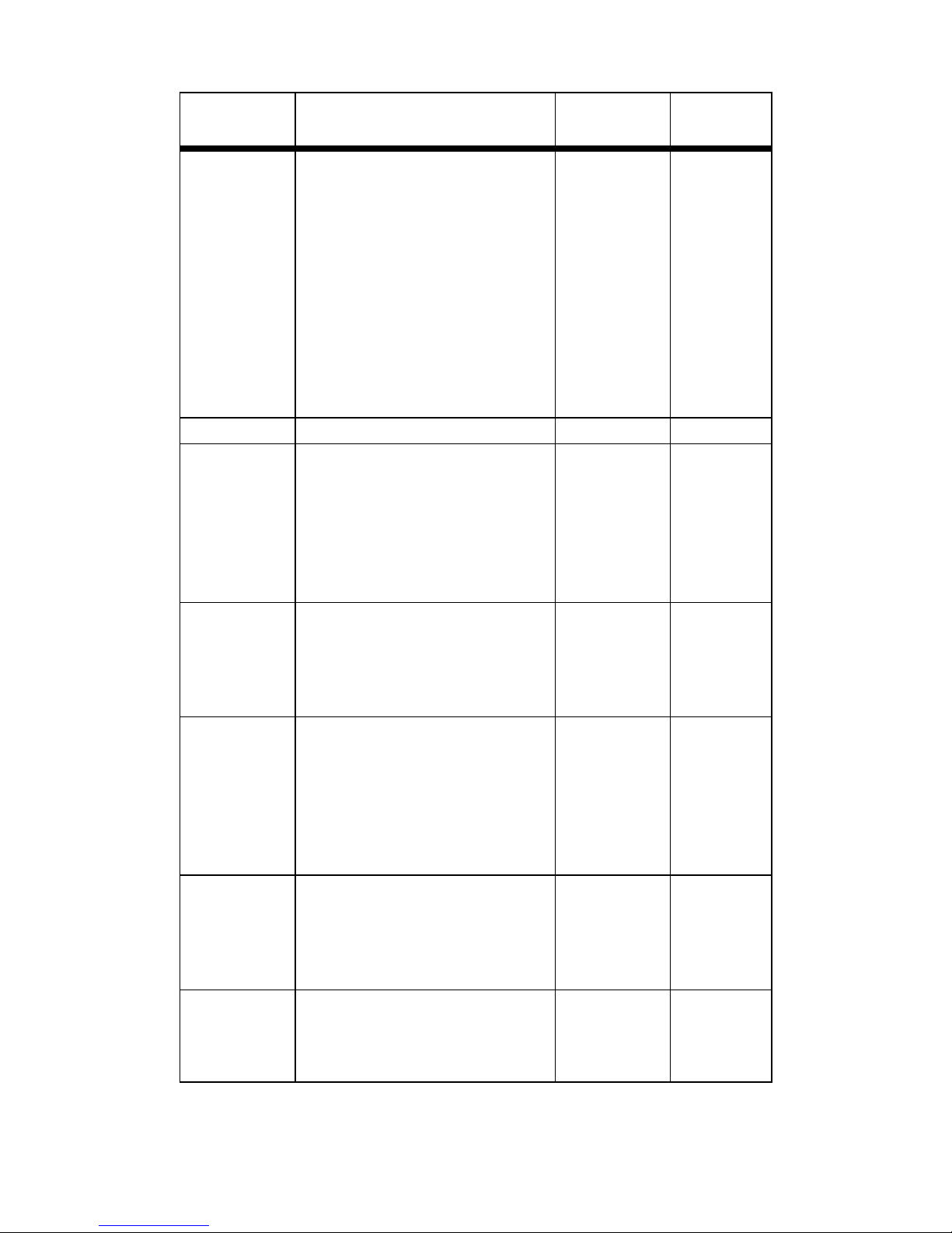
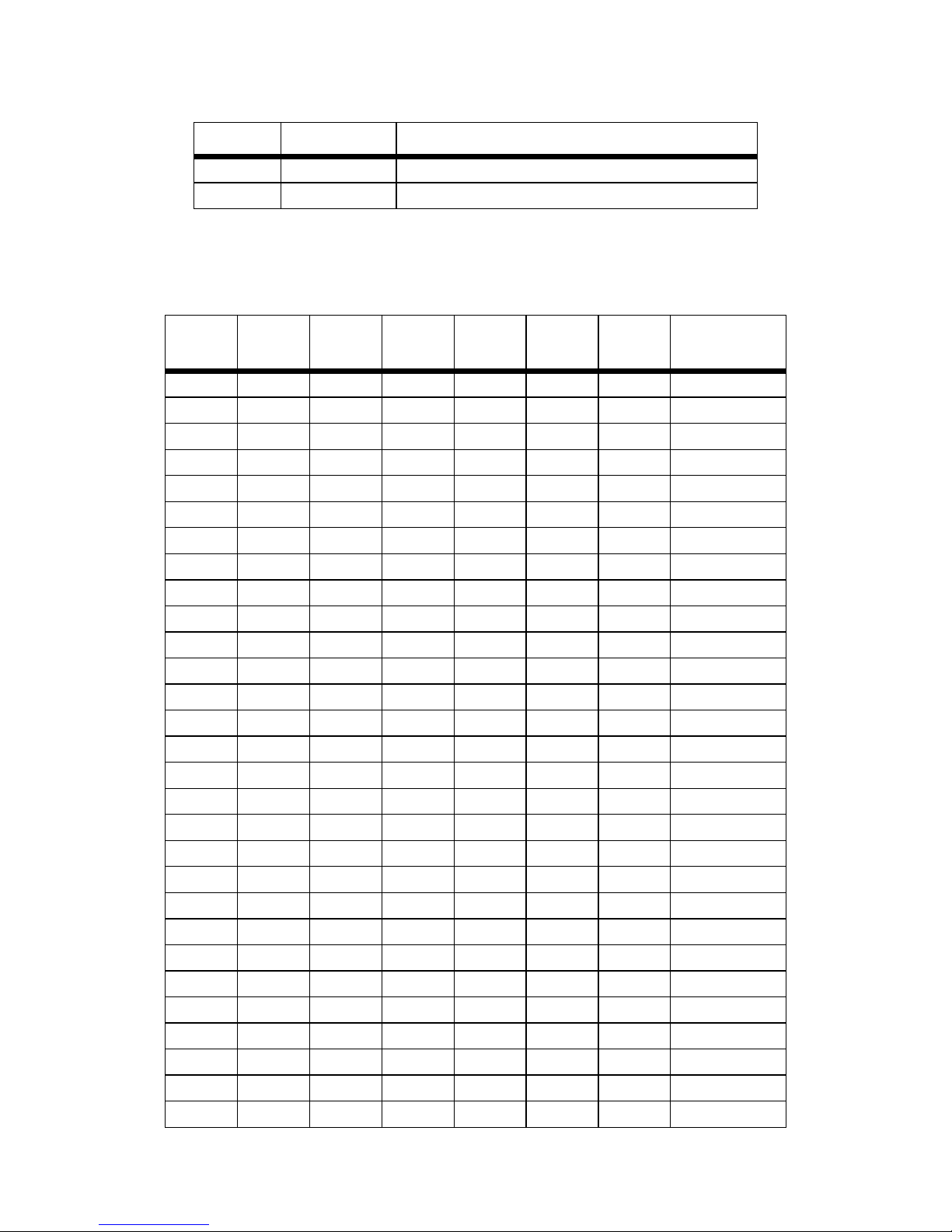
The Model 3088 provides the following parameters for configuring
the unit.
Parameter Description
Password The password used to login
to the console.
Circuit ID The circuit ID used to identify
the unit.
Front Panel
Switches
If the unit is populated with
front panel switches, the y can
be used to start and stop test
modes. If they are disabled,
however, the front panel
switch settings will be
ignored.
DTE Loops The V.35 interface can
request LALs and RDLs
using its RRDL and RLAL
pins. If DTE loops are disabled, requests for loopbac ks
on these pins will be ignored.
TX Clock The serial TX data can be
sampled on either the falling
edge (normal) or rising edge
(inverted) of the TX clock.
Timeslots The number of DSL timeslots.
This controls both the DSL and
the serial data rate. The data
rate is calculated by the equation: data r ate = #timeslots x
64k
Possible
Values
Character
strings 1–9
characters
long.
Character
string 1–64
characters
long.
Enabled or
Disabled
Enabled or
Disabled
Normal or
Inverted
1–72 4
Default
Value
patton
Patton
Model
3088
Enabled
Enabled
Normal
9
Page 10
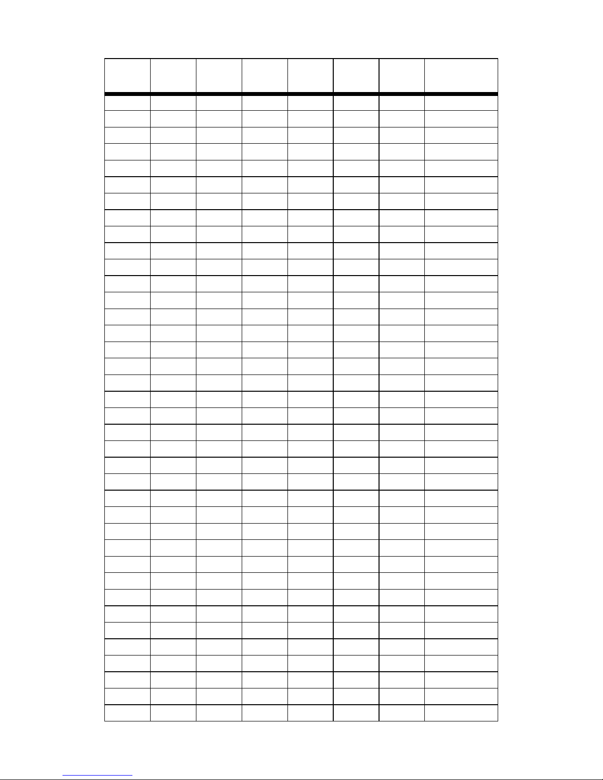
Parameter Description
Possible
Values
Default
Value
Clock
Mode
Controls DSL and serial clock
sources. Internal clock mode
means the 3088 provides its
own clock to both the serial
Internal,
External,
or Receive
Recover
interface and the DSL link.
External clock mode means
the serial interface provides
the clock used for the DSL
link. Receive recover clock
mode means the DSL link
provides the clock to the
serial interface.
Annex The G.991.2 Annex. A or B B
Line Probe A proprietary method to set
the DSL data rate to the best
Enabled or
Disabled
rate that both units can support. Used for rate adaptive
applications. This can only be
used for data rates of 3–36
timeslots.
Loopback The 3088 provides both a
local loopback (LAL) and a
OFF, LAL,
or RDL
remote loopback (RDL). This
can be used to troubleshoot
problems.
Pattern The 3088 provides an inter-
nal PRBS pattern generator
OFF, 511,
or 511E
and detector that can be
used to run BER tests without
external equipment. The patterns offered are 511 and 511
with errors.
DSL Error
Monitor
Maximum
Intervals
The number of errors allowed
in an interval before considering the interval errored. A
value of 0 disables the error
0–255 3
monitor.
DSL Error
Monitor
The length, in seconds, of
an interval.
1–255 1
Interval
Time
Receive
Recover
Disabled
OFF
OFF
10
Page 11
Parameter Description
Possible
Values
Default
Value
DSL Error
Monitor
Interval
The number of errored intervals allowed before restarting the DSL link.
1–255 3
Count
DSL Error
Monitor
Total Inter-
The number of intervals to
inspect before disabling the
error monitor.
0–255 10
vals
DSL Error
Monitor
Startup
The length, in seconds, to wait
after DSL link comes up before
enabling the error monitor .
0–255 5
Delay
4.1 CONFIGURING THE DIP SWITCHES
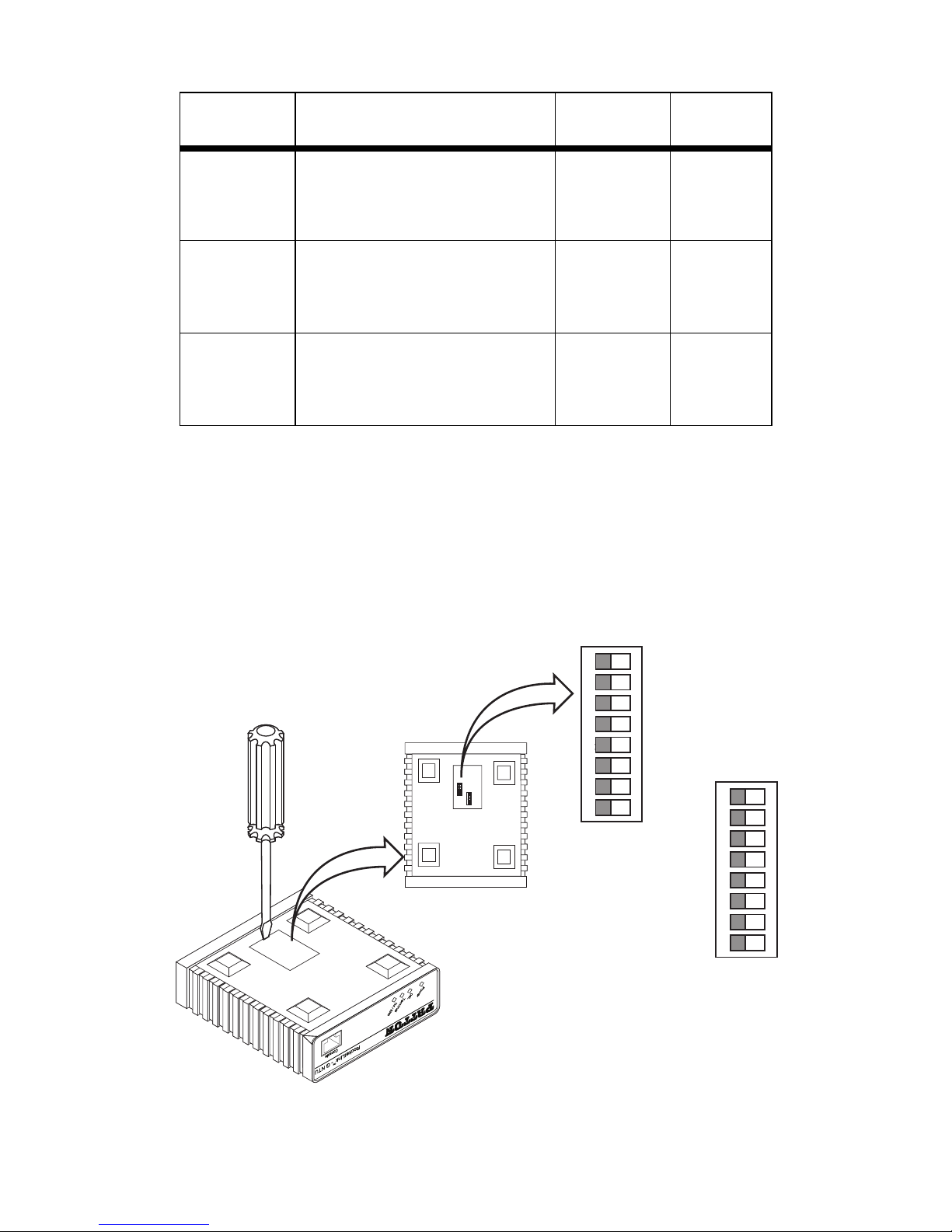
The Model 3088 is equipped with two sets of DIP switches, which allo w configuration of the unit for a wide v ariety of applications. This section describes
switch locations and e xplains all possib le configurations .
The two sets of DIP switches are externally accessible from the underside of the Model 3088 (see figure 2).
ON
12 3 45 67 8
ON
12 3 45 67 8
S1
S2
Model 1194E Single Mode Fiber - Quad G.703/G.704 Modem
G.703/G.704 Test Modes
1 2 3 4 5 6 7 8
ON
1 2 3 4 5 6 7 8
ON
S1
S2
Figure 2.
Underside of Model 3088 showing location of DIP switches
11
Page 12
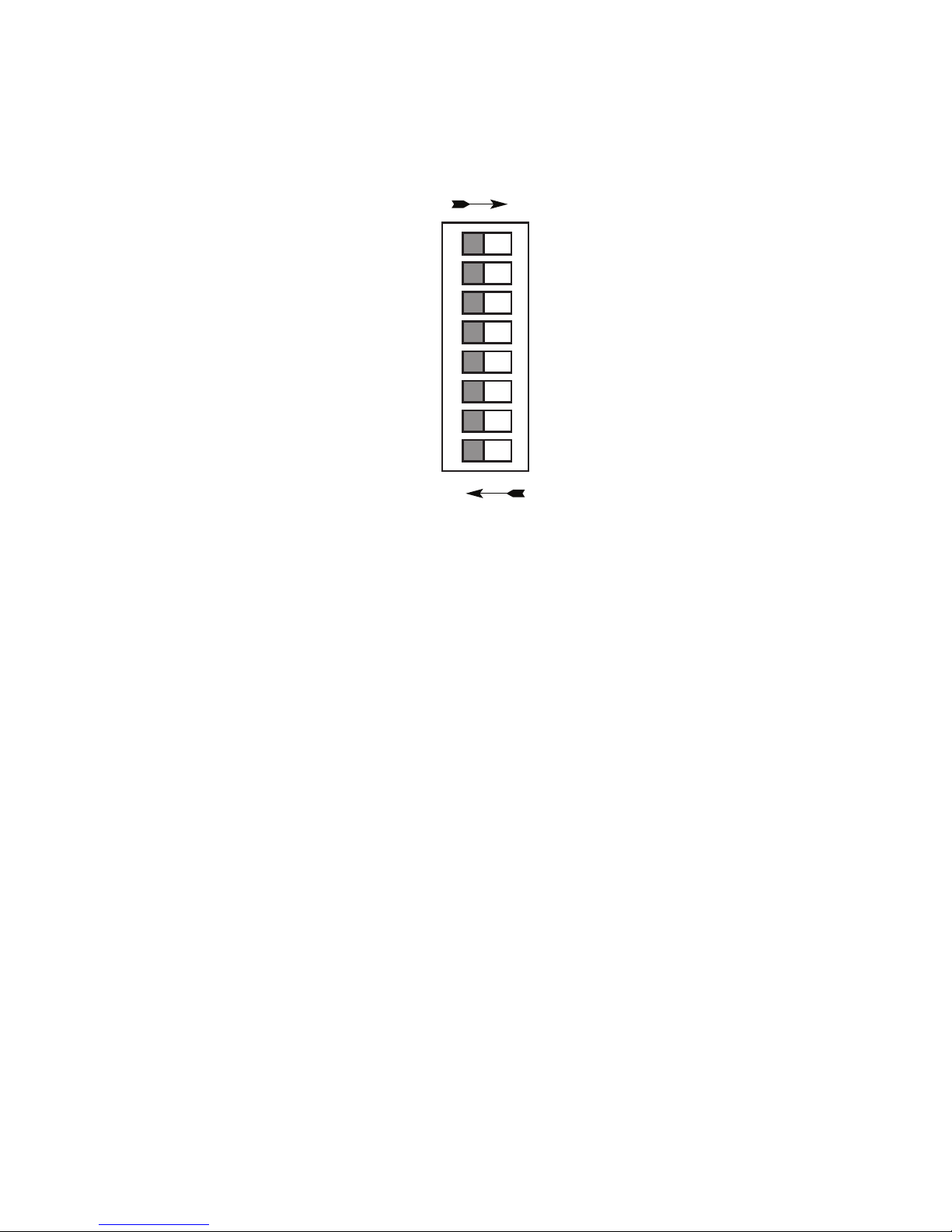
The two sets of DIP switches on the underside of the Model 3088 are
referred to as S1 and S2. As shown in figure 3, the orientation of all DIP
switches is the same with respect to “ON” and “OFF” positions
ON
1 2 3 4 5 6 7 8
ON
OFF
Figure 3.
Close-up of configuration switches (all sets are identical appearance)
4.2 SYSTEM RESET MODE
System reset mode is entered by switching all DIP switches to the OFF
position and power cycling the unit. A VT100 emulator configured for
19,200 kbps/1 stop bit/ no parity/ XON-XOFF flow control can be used to
access the console. Upon restart, you will see the message
“Reset Mode”.
System reset mode provides two functions:
• Software upgrades
• Configuration reset to factory defaults
Software Upgrades
The software is upgraded by waiting for the “Reset Mode” message.
Then, the user can send an Intel HEX file supplied by Patton. After the
VT100 emulator has finished sending this file, the 3088 will respond with
a message stating how many errors were detected. The user may then
set the DIP switches to the desired configuration and power cycle the
unit to run the upgraded software.
12
Page 13
Configuration Reset to Factory Defaults
To recover from a forgotten password, the user may reset the unit to its
factory configuration. After seeing the “Reset Mode” message, the user
should type the ‘*’ key. This will result in a ‘:’ prompt. At the prompt, the
user should enter the command reset. This will restore the unit to the factory configuration. The unit can then be restarted with the settings
in place.
4.3 DIP SWITCH SETTINGS
The 3088 can be configured with DIP switches. If the DIP switches are
set to anything other than all ON, then the unit will be in DIP switch configuration. In DIP switch configuration, the console and EOC cannot be
used to change configuration.
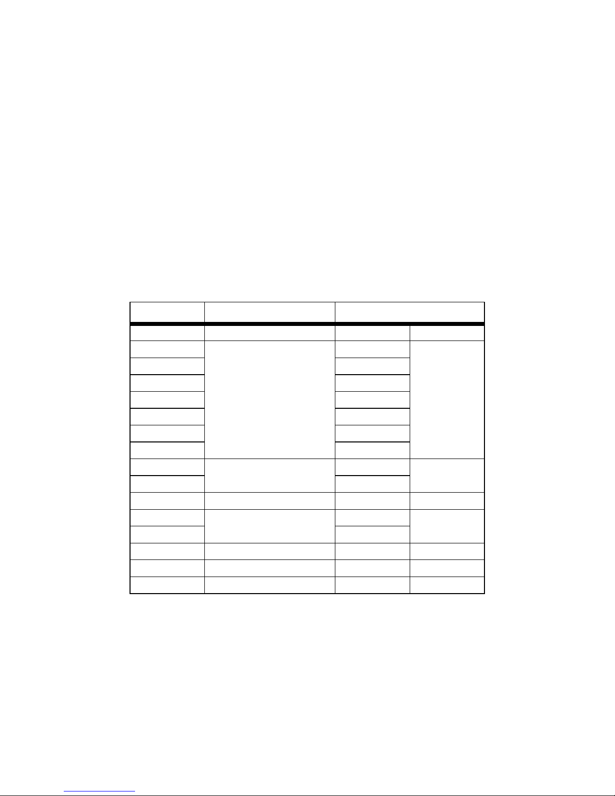
The following table describes the DIP switch functions.
Position Function Factory Default
S1-8 TX Clock ON Normal
S1-7 Data Rate ON 256K
S1-6 ON
S1-5 ON
S1-4 ON
S1-3 ON
S1-2 OFF
S1-1 OFF
S2-8 Reserved OFF
S2-7 OFF
S2-6 DTE Loops OFF Disabled
S2-5 Clock Mode OFF ReceiveS2-4 ON
Recover
S2-3 Annex OFF Annex B
S2-2 Line Probe ON Disabled
S2-1 Front Panel Switches OFF Enabled
13
Page 14
S1-8: TX Clock
S1-8 Setting Description
ON Normal TD sampled on falling edge of TX clock.
OFF Inverted TD sampled on rising edge of TX clock.
S1-7 – S1-1: Data Rate
This setting controls the DSL data rate and the serial data rate.
S1-7 S1-6 S1-5 S1-4 S1-3 S1-2 S1-1
Data Rate
(kbps)
ON ON ON ON ON ON OFF 64
ON ON ON ON ON OFF ON 128
ON ON ON ON ON OFF OFF 192
ON ON ON ON OFF ON ON 256
ON ON ON ON OFF ON OFF 320
ON ON ON ON OFF OFF ON 384
ON ON ON ON OFF OFF OFF 448
ON ON ON OFF ON ON ON 512
ON ON ON OFF ON ON OFF 576
ON ON ON OFF ON OFF ON 640
ON ON ON OFF ON OFF OFF 704
ON ON ON OFF OFF ON ON 768
ON ON ON OFF OFF ON OFF 832
ON ON ON OFF OFF OFF ON 896
ON ON ON OFF OFF OFF OFF 960
ON ON OFF ON ON ON ON 1024
ON ON OFF ON ON ON OFF 1088
ON ON OFF ON ON OFF ON 1152
ON ON OFF ON ON OFF OFF 1216
ON ON OFF ON OFF ON ON 1280
ON ON OFF ON OFF ON OFF 1344
ON ON OFF ON OFF OFF ON 1408
ON ON OFF ON OFF OFF OFF 1472
ON ON OFF OFF ON ON ON 1536
ON ON OFF OFF ON ON OFF 1600
ON ON OFF OFF ON OFF ON 1664
ON ON OFF OFF ON OFF OFF 1728
ON ON OFF OFF OFF ON ON 1792
ON ON OFF OFF OFF ON OFF 1856
14
Page 15
S1-7 S1-6 S1-5 S1-4 S1-3 S1-2 S1-1
Data Rate
(kbps)
ON ON OFF OFF OFF OFF ON 1920
ON ON OFF OFF OFF OFF OFF 1984
ON OFF ON ON ON ON ON 2048
ON OFF ON ON ON ON OFF 2112
ON OFF ON ON ON OFF ON 2176
ON OFF ON ON ON OFF OFF 2240
ON OFF ON ON OFF ON ON 2304
ON OFF ON ON OFF ON OFF 2368
ON OFF ON ON OFF OFF ON 2432
ON OFF ON ON OFF OFF OFF 2496
ON OFF ON OFF ON ON ON 2560
ON OFF ON OFF ON ON OFF 2624
ON OFF ON OFF ON OFF ON 2688
ON OFF ON OFF ON OFF OFF 2752
ON OFF ON OFF OFF ON ON 2816
ON OFF ON OFF OFF ON OFF 2880
ON OFF ON OFF OFF OFF ON 2944
ON OFF ON OFF OFF OFF OFF 3008
ON OFF OFF ON ON ON ON 3072
ON OFF OFF ON ON ON OFF 3136
ON OFF OFF ON ON OFF ON 3200
ON OFF OFF ON ON OFF OFF 3264
ON OFF OFF ON OFF ON ON 3328
ON OFF OFF ON OFF ON OFF 3392
ON OFF OFF ON OFF OFF ON 3456
ON OFF OFF ON OFF OFF OFF 3520
ON OFF OFF OFF ON ON ON 3584
ON OFF OFF OFF ON ON OFF 3648
ON OFF OFF OFF ON OFF ON 3712
ON OFF OFF OFF ON OFF OFF 3776
ON OFF OFF OFF OFF ON ON 3840
ON OFF OFF OFF OFF ON OFF 3904
ON OFF OFF OFF OFF OFF ON 3968
ON OFF OFF OFF OFF OFF OFF 4032
OFF ON ON ON ON ON ON 4096
OFF ON ON ON ON ON OFF 4160
OFF ON ON ON ON OFF ON 4224
OFF ON ON ON ON OFF OFF 4288
15
Page 16

S1-7 S1-6 S1-5 S1-4 S1-3 S1-2 S1-1
Data Rate
(kbps)
OFF ON ON ON OFF ON ON 4352
OFF ON ON ON OFF ON OFF 4416
OFF ON ON ON OFF OFF ON 4480
OFF ON ON ON OFF OFF OFF 4544
OFF ON ON OFF ON ON ON 4608
Loops
The V.35 interface has pins two pins, one to request an LAL and the
other to request and RDL. If DTE loops are enabled, then when these
pins are asserted, the 3088/C will start a local loopback or a remote
loopback. If DTE loops are disabled, these requests will be ignored.
S2-6 Setting
ON Enabled
OFF Disabled
S2-5 – S2-4: Clock Mode
The 3088 has three clock modes: internal, external, and receive-recover.
S2-5 S2-4 Clock Mode Description
ON ON Internal 3088 provides both the serial
and the DSL clock
ON OFF External 3088 uses the TX clock from
the serial interface for the DSL
clock.
OFF OFF Receive-
Recover
3088 uses the RX clock from
the DSL interface for the
serial clock.
OFF OFF Reserved
16
Page 17

S2-3: Annex A/B
Annex A is typically used in North American-like networks, whereas
Annex B is typically used in European-like networks. The different
annexes specify different PSD (power spectral density) masks because
of the difference in T1 and E1 PSDs.
S2-3 Annex
ON A
OFF B
S2-2: Line Probe
Line probe is a mechanism that determines the highest rate (192K to
2304K) that the DSL link can reliably support. This takes place during
training. The DSL rate will be set to the rate that line probe determines.
Note that both the CO and CPE unit must have line probe enabled for it
to take effect.
Line probe could be used to determine the best rate the line will support,
and then the user could set the units for that rate and disable line probe
so that the rate won’t change without the user’s knowledge.
S2-2 Line Probe
ON Disabled
OFF Enabled
S2-1: Front Panel Switches
The 3088 is optionally equipped with front panel switches for controlling
test modes. If front panel switches are disabled, then their settings will
be ignored.
S2-1 Front Panel Switches
ON Disabled
OFF Enabled
3.4 Console
The 3088 offers a console command line interface. A VT100 emulator
configured to 19,200 kbps/1 stop bit/ no parity/ XON-XOFF flow control
can be used to access the console.
Through the console, the following variables can be configured:
•
Password
: The password used to login to the console.
17
Page 18

•
Circuit ID
: The circuit ID communicated to other units via EOC.
EOC
(Embedded Operations Channel) is an out-of-band channel specified
in the G.991.2 standard for SHDSL. We use standard EOC messages
for our remote loopback. The 3088 also supports proprietary EOC
messages that allow a 3096RC to configure it.
•
Clock Mode:
The following options are available:
– Internal: The 3088 provides the clock to both the serial and
DSL interfaces.
– External: The serial interface provides the clock used for the
DSL interface (V.35 only).
– Receive Recover: The clock recovered from the DSL is provided to
the serial interface.
•
Data Rate
: Both the serial and DSL data rates are set by specifying
the number of 64k timeslots.
•
Annex
: Either G.991.2 Annex A or Annex B.
•
DSL Error Monitor Max Interval Errors
: The number of errors
allowed in an interval before considering the interval errored. A value
of ‘0’ disables the DSL error monitor.
•
DSL Error Monitor Interval Time
: The length in seconds of
an interval.
•
DSL Error Monitor Interval Count
: The number of errored intervals
allowed before restarting the DSL link.
•
DSL Error Monitor Total Intervals
: The number of intervals to inspect
before disabling the error monitor.
•
DSL Error Monitor Startup Delay
: The length in seconds to wait after
the DSL link is established before starting the error monitor.
•
Test Modes
: Loopbacks (LAL or RDL) and PRBS (pseudo random
binary sequence) BER tests (511 or 511 with errors)
•
Line Probe
: Enable or disable Line Probe for rate
adaptive applications.
The following status information is available through the command
line interface:
•
LEDs
: Which software controlled LEDs are currently on.
18
Page 19

•
FPSW Settings
populated with them).
•
Configuration Mode
or software.
•
DSL Link State
•
DSL Sync State
Sync.
: What the front panel switches are set to (if the unit is
: Whether the 3088 is configured b y DIP switches
: In Progress, Success, Deactivated, or Idle.
: Out of Sync, Acquiring Sync, In Sync, or Losing
Note DSL Link State vs. DSL Sync State
describes whether the DSL is training (in progress), linked (success), deactivated (we don’t have an option to deactivate the
modem, so the user should not see this), or idle.
The DSL sync state describes whether no sync words have
been found (out of sync), there are no sync word errors (in
sync), or whether we are transitioning from out of sync to in sync
(acquiring sync) or vice versa (losing sync). Typically, when the
link is training, the sync state goes from out of sync to acquiring
sync to in sync.
•
DSL Actual Rate
: The actual rate at which the DSL link is running
—The DSL link state
(minus DSL overhead).
•
DSL Line Condition
•
Noise Margin Ratio
: Good or Poor.
: the maximum tolerable increase in external
noise power that still allows for BER of less than 1x 10–
•
DSL Error Counters
: The following error counters are available:
– CRC
7
.
– LOSW (Loss of Sync Word)
– TX FIFO Full
– TX FIFO Empty
– TX FIFO Slip
– TX Stuff
– RX FIFO Full
– RX FIFO Empty
– RX FIFO Slip
19
Page 20

Help Commands
The following commands are provided to help the user find the
correct command:
•
help:
•
system help:
Lists all the commands that the console recognizes.
Lists all the commands that start with system that the
console recognizes.
•
system set help:
Lists all the commands that start with system set
that the console recognizes.
•
system show help:
Lists all the commands that start with system
show that the console recognizes.
•
dsl help:
Lists all the commands that start with dsl that the
console recognizes.
•
dsl set help:
Lists all the commands that start with dsl set that the
console recognizes.
•
dsl show help:
Lists all the commands that start with dsl show that
the console recognizes.
•
dsl show errcntr help:
Lists all the commands that start with dsl show
errcntr that the console recognizes.
System Configuration Commands
The following commands allow the user to configure the system:
•
system set password <password>:
•
system set circuitid <circuitid>:
•
system set timeslots <1–72>:
Sets the number of DSL timeslots. The
Sets the system password.
Sets the circuit ID.
data rate is calculated by 64K x timeslots.
20
Page 21

•
system set clockmode <internal|external|receiverecover>:
Sets
the clock mode. Internal clock mode means the 3088 provides the
clock to both the DSL and the serial interface. External clock mode
means the 3088 uses the serial transmit clock as its DSL transmit
clock (V.35 only). Receive recover clock mode means that the 3088
uses the DSL receive clock as its DSL transmit clock and as the serial
receive clock.
Note X.21 External Clock Mode
DCE to provide the clock used f or both tr ansmitting data and for
sampling receive data. When the 3088/D is set as a DCE, it may
be used in internal or receive recover clock modes. The DSL
generates a clock that is provided to the X.21 interface.
When the 3088/D is a DTE, it may be used in external clock
mode. The X.21 interface needs to provide the clock. This clock
is used by the DSL to sample the serial data and also to update
the receive data.
The 3088 is set for either DCE or DTE by flipping the daughtercard. The 3088 is a DCE if DCE points away from the serial
interface toward the front of the 3088. Note that this is different
than the 3086/D.
—The X.21 interface expects the
The following commands allow the user to view the current
system configuration:
•
system show circuitid
•
system show timeslots:
: Shows the circuit ID.
Shows the number of timeslots. The data
rate can be calculated by 64K x timeslots.
• system show clockmode: Shows the clock mode.
Any changes to the system configuration or the DSL configuration will be
lost on the next power cycle unless the changes are saved. The command system save config is used to save the changes.
System Status Commands
The following commands show system status:
• system show status: Shows the following system status information:
LEDs, DSL test mode, front panel switch settings, DSL link state, and
configuration mode.
• system show configmode: Shows the configuration mode. If the DIP
switches are set to all on, then the configuration mode is DIP switch.
Otherwise, the configuration mode is software. In DIP switch configuration mode, the system configuration cannot be changed through
either the console or EOC.
21
Page 22

• system show leds: Shows the current state of all software controlled
LEDs.
• system show fpsw: Shows the current front panel switch settings.
DSL Configuration Commands
The following commands are used to configure the DSL:
• dsl set annex <a|b>: Set the annex.
• dsl set lineprobe <enabled|disabled>: Enable or disable line probe.
• dsl set loopback <off|lal|rdl>: Start or stop loopbacks.
• dsl set pattern <off|511|511e>: Start or stop PRBS generator and
BER meter.
DSL Error Monitor
Startup Delay Interval 1 Interval 2 … Interval totint
ïflstartdelayðïflinttimeðïflinttimeðïflinttimeðïflinttimeð
The DSL error monitor inspects intervals to see if they hav e met the error
threshold (maxint). If the error monitor finds a certain number (intcnt) of
intervals that meet or exceed the error threshold, it will restart the DSL
link. The error monitor will wait (startdelay) seconds after the DSL link
comes up before it begins monitoring errors. After the startup delay, it will
check the number of errors that have occurred during each (inttime) seconds to see if they meet the error threshold. The error monitor inspects
(totint) intervals before it stops.
Note Setting maxint to 0 disables the error monitor and setting totint
to 0 causes the error monitor to run continuously.
The following commands configure the error monitor:
• dsl set errmon maxint <maxint>: Sets the number of errors allowed
in an interval causes it to be considered an errored interval. If this is
set to ‘0’, then the error monitor is disabled.
• dsl set errmon inttime <inttime>: Sets the length of each interval.
• dsl set errmon intcnt <intcnt>: Sets the number of errored intervals
that causes the DSL link to restart.
• dsl set errmon totint <totint>: Sets the n umber of intervals to inspect
for errors bef ore disab ling the error monitor. If this is set to ‘0’, then the
error monitor will run continuously.
22
Page 23

• dsl set errmon startdelay <startdelay>: Sets the n umber of seconds
to wait after the DSL link comes up before the error monitor starts
inspecting intervals.
The following commands display the current DSL configuration:
• dsl show annex: Shows the currently selected G.SH Annex.
• dsl show lineprobe: Shows whether or not Line Probe is
currently enabled.
• dsl show loopback: Shows which loopback is currently running.
• dsl show pattern: Shows what PRBS pattern is currently running.
The following commands display the current DSL error
monitor configuration:
• dsl show errmon maxint: Shows the maximum errors allowed in an
interval before it is considered errored.
• dsl show errmon inttime: Shows the length in seconds of
each interval.
• dsl show errmon intcnt: Shows the number of errored intervals
allowed before restarting.
• dsl show errmon totint: Shows the number of intervals to monitor
before disabling the error monitor.
• dsl show errmon startdelay: Shows the length in seconds to wait
after the DSL link comes up before starting the error monitor.
Changing the data rate (system set timeslots), the clock mode (system
set clockmode), the Annex (dsl set annex), or Line Probe (dsl set
lineprobe), or the DSL error monitor settings will not take effect on the
DSL link until the link restarts. The dsl start command restarts the
DSL link.
DSL Status Commands
The following commands display DSL status:
• dsl show status: Shows the following DSL status information: link
state, sync state, link speed, error counters, line condition, and noise
margin.
• dsl show linkstate: Shows the state of the DSL link: idle, success,
deactivated, or in progress.
23
Page 24

• dsl show syncstate: Shows the sync state of the DSL link: out of
sync, acquiring sync, in sync, or losing sync
• dsl show linkspeed: Shows the actual DSL data rate (minus
DSL overhead)
• dsl show linecond: Shows the line condition: good or poor
• dsl show nmr: Shows the noise margin ratio.
• dsl show errcntrs: Shows the following error counters: CRC, LOSW,
TX FIFO Full, TX FIFO Empty, TX FIFO Slip, TX Stuff, RX FIFO Full,
RX FIFO Empty, and RX FIFO Slip.
• dsl show errcntr crc: Shows the number of CRC errors that have
occurred since either startup or the last time that error counters
were cleared.
• dsl show errcntr losw: Shows the number of LOSW errors that have
occurred since either startup or the last time that error counters
were cleared.
• dsl show errcntr txfifofull: Shows the number of TX FIFO Full errors
that have occurred since either startup or the last time that error
counters were cleared.
• dsl show errcntr txfifoempty: Shows the number of TX FIFO Empty
errors that have occurred since either startup or the last time that error
counters were cleared.
• dsl show errcntr txfifoslip : Shows the number of TX FIFO Slip errors
that have occurred since either startup or the last time that error
counters were cleared.
• dsl show errcntr txstuff: Shows the number of TX Stuff errors that
have occurred since either startup or the last time that error counters
were cleared.
• dsl show errcntr rxfifofull : Shows the number of RX FIFO Full errors
that have occurred since either startup or the last time that error
counters were cleared.
• dsl show errcntr rxfifoempty: Shows the number of RX FIFO Empty
errors that have occurred since either startup or the last time that error
counters were cleared.
• dsl show errcntr rxfifoslip : Shows the number of RX FIFO Slip errors
that have occurred since either startup or the last time that error
counters were cleared.
24
Page 25

The dsl clear errcntrs command clears the error counters.
Remote Console
Provided that there is a DSL link to a second 3088, a user may login to
the first 3088’s console and enter the remote console command to
access the second 3088’s console. Using this remote console feature,
the user can configure and query the status of the second 3088 from a
remote location. When the user is finished with the remote console, the
logout command can be used to return to the local console.
Example Command Line Interface Session
password: ******
> system set circuitid “3088 Circuit ID”
> system set timeslots 3
> system set clockmode internal
> dsl set annex b
> dsl set lineprobe disabled
> system save config
> dsl start
> system show status
leds: power: on dsl: on tm/er: off
dsl test mode:
ber status: idle
errors: 0
time: 0
front panel switches: sw1: normal sw2: normal
dsl link state: success
configuration mode: software
> dsl show status
link state: success
sync state: in sync
link speed: 192k
error counters:
crc: 0
losw: 0
tx fifo full: 0
tx fifo empty: 0
tx fifo slip: 0
tx stuff: 0
rx fifo full: 0
rx fifo empty: 0
rx fifo slip: 0
line condition: good
noise margin: 3.5
> remote console
25
Page 26

password: ******
> dsl clear errcntrs
> dsl show errcntrs
crc: 0
losw: 0
tx fifo full: 0
tx fifo empty: 0
tx fifo slip: 0
tx stuff: 0
rx fifo full: 0
rx fifo empty: 0
rx fifo slip: 0
> logout
exiting remote console
> dsl set loopback rdl
> dsl set pattern 511e
> dsl show testmode
ber status: in progress
errors: 42
time: 12
> dsl set pattern off
> dsl set loopback off
> logout
password:
4.4 ROCKETLINK PLUG ‘N’ PLAY
The RocketLink Plug ‘n’ Play feature allows ISPs, carriers and PTTs to
quickly upgrade the link speed for a customer without requiring a visit to
re-configure the Customer Premise (CP) Model 3088. This feature also
allows service providers to set up all of the configurations at the Central
Office (via the ForeFront AIS system) before installing the stand alone
units, saving time spent configuring or re-configuring DIP switches.
Note RocketLink Plug ‘n’ Play is only available when using a Fore-
Front Model 3096RC as the CO unit.
The RocketLink Plug ‘n’ Pla y f eature allows the user to configure the DTE
rate (bandwidth allocation, see Switches S1-1 through S1-7) of the CP
unit via the
ForeFront Model 3096RC at the Central Office (CO). The
stand alone unit at the Customer Premise (CP) site will automatically
configure itself to the DTE rate (Bandwidth Allocation) defined at the
Model 3096RC. Other configuration parameters remain in the
default setting.
26
Page 27

Follow the instructions below to activate RocketLink Plug ‘n’ Play
between CO (Model 3096RC and CP (Model 3088) units:
• Set the Model 3096RC (CO) to either Internal or External clocking
mode as defined by the application.
• Set the Model 3088 (CP) to “RocketLink Plug-and-Play CP” by setting
S1 and S2 DIP switches in the ON position as described in figure 4.
3096RC
(CO)
DIP Switches or NMS configured
according to specific application
requirements
Figure 4. Typical RocketLink Plug ‘n’ Play Application
DSL Span
3088
(CP)
DIP Switches all in ON position
When the CO and CP units connect over DSL, the CP will enter a predefined default configuration (Receive Recovered Clocking). During the
negotiation process between the units, the CO unit will configure the
DTE rate/line rate on the CP unit as defined by the settings of the CO
unit. When additional bandwidth is required, only the configuration of the
CO unit should be changed. This feature gives ISPs , LECs and PTTs the
ability to provision bandwidth on an as needed basis to customers.
27
Page 28

5.0 INSTALLATION
Once the Model 3088 is properly configured, it is ready to connect to the
twisted pair interface, to the serial port, and to the power source. This
section tells you how to make these connections.
5.1 CONNECTING THE TWISTED PAIR INTERFACE
The Model 3088 supports communication between two DTE devices
as follows:
Using 24 AWG (.5 mm) wire:
• up to 32,000 feet (9.7 km) at 192 kbps
• up to 18,500 feet (5.6 km) at 2.312 Mbps on
Using 26 AWG (.4 mm) wire:
• up to 23,000 feet (7 km) at 192 kbps
• up to 13,200 feet (4 km) at 2.312 Mbps on
Two things are essential:
1. These units work in pairs. Both units at the end of the twisted pair
DSL span must be set for the same DTE rate—one unit set as CO,
the other as CP.
2. To function properly, the Model 3088 needs one twisted pair of
metallic wire. This twisted pair must be unconditioned, dry, metallic
wire, between 19 (.9mm) and 26 AWG (.4mm) (the higher number
gauges will limit distance). Standard dial-up telephone circuits, or
leased circuits that run through signal equalization equipment, or
standard, flat modular telephone type cable, are not acceptable.
28
Page 29

The RJ-45 connector on the Model 3088’s twisted pair interface is polarity insensitive and is wired for a two-wire interface. The signal/pin relationships are shown in figure 5.
\
3088/D (V.35, female DB-15)
3088/CA (V.35, female DB-25)
Figure 5. Model 3088 V.35/X.21 interfaces.
5.2 CONNECTING THE MODEL 3088/CA (V.35)
SERIAL INTERFACE
Model 3088/CA supports V.35 serial port connections. This section
describes how to connect the serial ports to your V.35 equipment.
Connecting the Model 3088/CA (V.35) to a “DTE” Device
The Model 3088/CA provides a V.35 DCE (data circuit terminating equipment) interface on an DB-25 female connector. As a DCE, this interface
is designed to connect to DTE equipment, such as a router. When connecting the V.35 interface of the Model 3088/CA to your DTE device, use
a V.35 straight-through cable (See figure 6). Appendix C describes pin
assignments and signal sources for the Model 3088/CA V.35 interface.
When purchasing or constructing an interface cable, refer to the pin diagrams in Appendix C as a guide.
DSL Span
Remote Model 3088
Straight-Through Cable
Model 3088/CA (DCE)
Figure 6. Connecting the Model 3088/CA to V.35 Serial DTE
V.35 Router (DTE)
29
Page 30

Connecting the Model 3088/CA (V.35) to a “DCE” Device
The Model 3088/CA provides a V.35 DCE (data circuit terminating equipment) interface on an DB-25 female connector. As a DCE, this interface
is designed to connect to DTE equipment, such as a router. However,
tail-circuit applications require connection to another DCE equipment,
such as a multiplexer. When connecting the V.35 interface of the Model
3088/CA to your DCE device (see figure 7), use a V.35 tail circuit cable.
Some applications may also require the installation of a V.35 tail-circuit
buffer to account for small differences in clock frequency between the
3088/CA and the V.35 DCE (Multiplexer).
DSL Span
Remote Model 3088
Straight-Through Cable
Model 3088/CA (DCE)
Figure 7. Connecting the Model 3088/CA to V.35 Serial DCE
V.35 Router (DTE)
5.3 CONNECTING THE MODEL 3088/D (X.21) SERIAL INTERFACE
Model 3088/D supports X.21 serial port connections. This section
describes how to connect the serial ports to your X.21 equipment.
Connecting the Model 3088/D (X.21) to a “DCE” or “DTE” Device
The Model 3088/D provides an X.21 interface on a DB-15 female connector. The X.21 interface default configuration is DCE for connection to
DTE (data terminal equipment) such as a router. However, the X.21 interface on the Model 3088/D may be configured as DTE (
data terminal equip-
30
Page 31

ment) for connection to DCE such as a modem or multiplexer. When
connecting the X.21 interface of the Model 3088/D to your DTE or DCE
device, use an X.21 straight-through cable (See figure 8).
DSL Span
Remote Model 3088)
Model 3088/D (DCE or DTE)
Figure 8. Connecting the Model 3088/D to X.21 DTE or DCE
Straight-Through 15-pin
D-Sub Cable
Router (DTE)
OR
Mux (DCE)
To change the DCE/DTE orientation from the def ault position (DCE), you
must open the case Model 3088/D case.
Opening the Case
To open the Model 3088/D case, insert a flat head screw driver into an
open slot on both sides of the case, as in figure 9. Twist the screw driver
head slightly and the top half of the case will separate from the lower
half, as in figure 9. Be careful not to damage the PC-board
mounted components.
Figure 9. Opening the 3088 case with a small screwdriver
31
Page 32

The DCE/DTE strap is located on the top side of the 3088/D pc board
(See figure 10, below). The arrows on the top of the strap indicate the
configuration of the X.21 port (for example, if the DCE arrows are pointing toward the DB-15 connector, the X.21 port is wired as a DCE).
Change the DCE/DTE orientation by pulling the strap out of its socket,
rotating it 180º, then plugging the strap back into the socket. You will see
that the DCE/DTE arrows now point in the opposite directions, showing
the new configuration of the X.21 port. To close the case, fit the 2 halves
together snugly and snap them back in place.
DB-15 Connector
Figure 10. Setting the DCE/DTE Strap
DCE/DTE Strap
5.4 CONNECTING POWER
The Model 3088 uses a 5 VDC, 2A universal input 100–240 VAC, power
supply (center pin is +5V). The universal input power supply has a male
IEC-320 power entry connector. This power supply connects to the
Model 3088 by means of a barrel jack on the rear panel. Many international power cords are available for the universal power supply (Please
refer to Appendix B for country-specific power cords.
The Model 3088 powers up as soon as it is plugged into an AC outlet-there is no power switch.
WARNING
There are no user-serviceable parts in the
power supply section of the Model 3088. Fuse
replacement should only be performed by qualified service personnel. Contact Patton Electronics Technical support at (301)975-1007, via our
web site at www.patton.com, or by e-mail at
support@patton.com, for more information.
32
Page 33

6.0 OPERATION
Once the Model 3088 is properly configured and installed, it should operate transparently. This sections describes power-up, reading the LED
status monitors, and using the built-in loopback test modes.
6.1 POWER-UP
To apply power to the Model 3088, first be sure that you have read section 5.4, “Connecting Power” on page 32, and that the unit is connected
to the appropriate power source. Power up the unit.
6.2 LED STATUS MONITORS
There are four LEDs that provide feedback on the state of the unit.
Figure 11 shows the location of the front panel LEDs. F ollowing figure 10
is a description of each LED’s function.
Figure 11. Model 3088/CA front panel
Power (Green)
The Power LED glows solid during normal operation. At startup, during
the POST, the LED blinks once every second. If the POST fails, the unit
does not enter normal operation, and the LED blinks once every
0.4 seconds.
DSL (Green)
The DSL LED glows solid while a DSL link is established. While the DSL
link is training it blinks once every second.
33
Page 34

Term (Green)
The Term LED glows solid under the following circumstances:
• 3088/CA with V.35 interface: If the serial interface has asserted DTR
• 3088/D with the X.21 interface:
– Configured as DCE: Indicates that the “Control” signals have
been asserted.
– Configured as DTE: Indicates that the “Indication” signals have
been asserted
TM/ER (Red)
The TM/ER LED is used to indicate that a test mode is in prog ress or an
error has been detected. It blinks once e v ery second while a test mode is
starting. It glows solid while a test mode is in progress . It b links once if an
error is detected either during a test mode, or in normal DSL operation.
6.3 TEST MODES
The 3088 offers test modes in the form of loopbacks, PRBS pattern generators, and combinations of both. This section discusses how the test
modes work. Figure 12 is a block digram of the Model 3088 with respect
to test modes.
511 Pattern
Generator
511 BER
DSL
Framer
Line
DSL
Framer
511 Pattern
Generator
511 BER
Meter
Figure 12. Model 3088 Block Diagram
Loopbacks
The 3088 supports both Local Analog Loopbacks (LAL) and Remote
Digital Loopbacks (RDL). These can be initiated either from the optional
front panel switches or by the console command dsl set loopback
<off|lal|rdl>. The data path for the LAL is shown in figure 13.
Meter
34
Page 35

.
511 Pattern
Generator
511 BER
Meter
DSL
Framer
Line
Figure 13. Local Analog Loopback diagram
DSL
Framer
511 Pattern
Generator
511 BER
Meter
The data received from the serial interface is looped back before going
out on the DSL line. Note that this loopback occurs after the pattern generator/BER meter. This means that running a 511 pattern is conjunction
with an LAL should result in no error detected by the meter.
The data path for the RDL is shown in figure 14.
511 Pattern
Generator
511 BER
Meter
DSL
Framer
Line
DSL
Framer
511 Pattern
Generator
511 BER
Meter
Figure 14. Remote Digital Loopback diagram
The RDL causes the remote unit to loop the data received from the DSL
line back to the DSL line.
Patterns
The 3088 can generate and detect 511 and 511 with Error patterns.
These can be initiated either by the optional front panel switches or by
the console command dsl set pattern <off|511|511e>. When the pattern
is started, the DSL framer uses its internal 511 pattern generator for its
DSL TX data instead of the data received from the serial interface. Also,
the framer’s internal BER Meter tries to detect a 511 pattern in the DSL
RX Data.
Because the BER Meter always runs when the pattern generator runs,
the meter will detect errors if either the pattern is not either looped back
or the remote unit is not transmitting a 511 pattern.
One point to note is that the way errors are generated in the 511E pattern generates CRC errors. This can cause the DSL error monitor to
restart the link if the thresholds are set low enough.
35
Page 36

7.0 REMOTE CONSOLE MANUAL INFORMATION
The PC user (near-end) may configure and verify status of the remote
3088 (far-end) via a Remote Console session. The PC user must log
onto the 3088 (near-end) unit to establish a remote console session.
Once done, the remote 3088 (far-end) appears as a unit which is locally
connected through the RS-232 console port. All commands are transmitted over the G.SHDSL link in the EOC channel.
Remote Console Session (RCS)
PC
(Near End)
RS-232
3088
3088
(Near End)
Figure 15. Remote control session diagram
DSL
(Far End)
7.1 ESTABLISHING A REMOTE CONSOLE SESSION
How to Connect
The following steps are to estab lish a connection to the remote 3088 (f arend) via Remote Console Session (RCS):
1. Configure a terminal emulation program (e.g., Hyperterminal) on PC
(near-end) for 19.2 kbps, 8 data bits, no parity, 1 stop bit, no flow
control. Connect it to the RS-232 console port of the 3088 (nearend).
2. At the password prompt, log in to the near-end Model 3088.
3. Ensure that a DSL link is established. You can verify an established
DSL link by using the system show status command or by checking
that the DSL LED is solid green. Upon executing the show status
command, the dsl link state is shown as
success
if the DSL link
is established.
4. At the command prompt, enter the command remote console.
5. Wait for the message
connection established
Console: Remote console
.
— If a DSL link is not established, or for some other reason the
3088 (far-end) does not respond in a reasonable amount of
time, the follo wing message appears:
timed out trying to connect
. Enter the command remote
Console: Remote console
console again.
36
Page 37

— If 3088 (Far End) already has an activ e remote console session
open, you will see the message
nection request rejected
. This can also happen if the remote
Console: Remote console con-
3088 (far-end) has an established remote console session with
the local 3088 (near-end) which has timed out.
6. Enter the password at the password prompt for the remote
console session.
Note The passwords for a local console session of the 3088 (near-
end) and the remote console session of the 3088 (far-end)
should be different for the purpose of security.
7. You should now be logged into the remote 3088(far-end) via the
remote console session. The communication with the remote 3088
(far-end) is essentially the same as having a local
console connection.
Note The local or remote 3088 may be CO or CPE, as long as there
is one of each. Either the CO or CPE unit may accept a remote
console connection.
Note With a remote console session open, a user at PC (far-end) is
blocked from using the local console . Upon typing anything, the
3088 (far-end) sends a message to the PC (far-end) stating
“Console: Remote console connection is open.”
37
Page 38

Figure 16 is a screenshot of opening a typical remote console session:
Log in to 3088 (Near End)
system show status command
shows that DSL link is not up
remote console command requests a
remote console session on 3088 (Far End)
Message informs us that the 3088 (Far
End) did not respond and a remote
console session was not opened
system show status command shows
that the DSL link state is success
remote console command requests a
remote console session on 3088 (Far End)
Message informs us that we are now
connected to the 3088 (Far End) console
We can now enter commands on
the remote console
Figure 16. Opening a typical remote console session
How to Disconnect
The remote console session ends under any of the following conditions:
• The user enters the command logout
• A timeout period of 5 minutes elapses since the user has entered a
command to the console.
• The DSL link drops.
The response upon logging out of the remote console session with the
command logout is
Console: Remote console connection lost
. The fol-
38
Page 39

lowing is what is display ed upon a user’s logging out of a remote console
session after logging in.
> remote console
>
Console: Remote console connection established.
password: ******
> logout
Console: Remote console connection lost.
>
The timeout period is a fixed, non-configurable parameter of 5 minutes.
If the remote 3088 (far-end) has received no command within 5 min utes ,
it automatically terminates the RCS. Once the RCS is terminated, the
PC (far-end) can establish a local console session if desired. However if
the PC (near-end) wishes to re-establish a RCS, it is able to do so
whether or not the PC (far-end) is in an active local session, because the
RCS has priority over a local console session. If the PC (near-end)
establishes an RCS while the PC (far-end) is on a local session, the PC
(far-end) is kicked off.
Differences in Local and Remote Control Session Behavior
Since the remote console session communication occurs over the
G.SHDSL link’s EOC channel, some commands via the RCS have
unusual effects.
• system upgrade: Do not issue this command via an RCS. A system
upgrade must be done via the local console connection. If you should
accidentally issue this command over an RCS, the remote 3088 (farend) waits indefinitely for input (which is the system upgrade image)
from the local console port of the 3088 (far-end). You must powercycle the remote 3088 (far-end) to return it to the normal operational
state. If this command is entered, 3088 (Far End) will have to be
power-cycled.
• dsl set loopback lal: When this command is issued over the RCS,
clearly the PC (near-end) can no longer communicate with the remote
3088 (far-end). See the diagram. Consequently the remote 3088 (farend) can no longer receive any commands over the DSL channel from
the PC (near-end). To recover from this situation, the DSL link will
have to be dropped prior to establishing the RCS again. A short explanation is in order. Since the remote 3088 (far-end) no longer receives
any commands from the PC (near-end), the RCS will time out in 5 minutes and attempts to send a disconnect message back to the local
39
Page 40

3088 (near-end). However the local 3088 (near-end) is unable to
receive this message and the local 3088 (near-end) does not know to
terminate the RCS. F or this reason, the DSL link must be dropped and
re-established. At this point, the RCS can be established anew.
Remote Console Session (RCS)
LAL
PC
(Near End)
PC
(Near End)
RS-232
3088
(Near End)
3088
(Far End)
RS-232
DSL
Figure 17. Remote control session with LAL diagram
• Restarting the dsl link will disconnect the remote console session.
Whether a DSL link is up or not has no effect on the operation of the
local console session.
40
Page 41

8.0 MODEL 3088 SOFTWARE UPGRADE FEATURE
The 3088 is software upgradeable through the console port. Software
images will be available in Intel Hex file format.
The software upgrade f eature is av ailable either b y pow ering up the 3088
will all dipswitches set to the “Off” position, or by entering the “system
upgrade” command on the command line interface. The software
upgrade takes appro ximately 5 minutes to complete . The 3088 will print ‘.’
to the screen while the software upgrade is in process. When the software upgrade completes, it will print a message stating that it is complete
and the number of errors, if any, that occurred.
Errors may occur during the software upgrade if the image is corrupt or if
there is a disruption in the console port connection. The 3088 will print a
message to the console port if it encounters any errors. In the e v ent of an
error, the portions of the old image may have been overwritten, and the
unit may not be able to boot into operational mode. However, the unit
may still boot into the software upgrade, so a new software image can
still be loaded to bring the unit back to an operational state.
Here is the software upgrade procedure:
1. Obtain a software image Hex file.
2. Turn off the 3088.
3. Switch all DIP switches to the “Off” position.
4. Turn on the 3088.
5. Transfer the software image hex file through the console (8 bits/no
parity/1 stop bit/XON-XOFF flow control).
6. When the transfer completes, turn the 3088 off.
7. Set the DIP switches for the proper configuration.
8. Turn on the 3088. It is now running the upgraded software.
41
Page 42

9.0 RESET CONFIGURATION TO FACTORY DEFAULTS
The configuration can be reset to factory defaults from the software reset
mode. This allows a user to recover from a forgotten password. To reset
to the configuration, follow these steps:
1. Power down the unit.
2. Set all DIP switches to the OFF position.
3. Connect a PC to the Console port.
4. Open a VT100 terminal emulator (such as HyperTerminal). Config-
ure the emulator for 19,200 kbps/1 stop bit/no parity/X-ON X-OFF
flow control.
5. Power up the unit. The terminal should display the following mes-
sage: “Reset Mode”.
6. Type the ‘*’ key. You will see a ‘: ‘ prompt.
7. Type the command ‘reset’.
8. When the command completes, the unit has been reset to
factory configuration.
9. Set the DIP switches to the desired configuration. Power cycle the
unit to begin using the new software.
42
Page 43

APPENDIX A
SPECIFICATIONS
A.1 CLOCKING MODES
Internal, external (V.35 only), or receive recovered
A.2 DTE RATE
All 64k steps from 64 to 4608 kbps
A.3 SERIAL INTERFACE
V.35 (Model 3088/CA), DCE orientation;
X.21 (Model 3088/D), DCE or DTE orientation depending on orientation
of daughter board mounted on the mother board.
A.4 SERIAL CONNECTOR
D-Sub-25 Female (Model 3088/CA)
D-Sub-15 Female (Model 3088/D)
A.5 DIAGNOSTICS
V.52 compliant (511/511E) pattern generator and detector with error
injection mode controlled by front-panel switch. Local and Remote Loopback control either by a front-panel switch or from the DTE interface.
A.6 STATUS LEDS
Power (Green)
The Power LED glows solid during normal operation. At startup, during
the POST, the LED blinks once every second. If the POST fails, the unit
does not enter normal operation, and the LED blinks once every
0.4 seconds.
DSL (Green)
The DSL LED glows solid while a DSL link is established. While the DSL
link is training it blinks once every second.
43
Page 44

Term (Green)
The Term LED glows solid under the following circumstances:
• 3088/CA with V.35 interface: If the serial interface has asserted DTR
• 3088/D with the X.21 interface:
– Configured as DCE: Indicates that the “Control” signals have
been asserted.
– Configured as DTE: Indicates that the “Indication” signals have
been asserted
TM/ER (Red)
The Test Mode/Error (TM/ER) LED is used to indicate that a test mode is
in progress or an error has been detected. It blinks once every second
while a test mode is starting. It glows solid while a test mode is in
progress. It blinks once if an error is detected either during a test mode,
or in normal DSL operation.
A.7 CONFIGURATION
Externally accessible DIP switches or SNMP managed through 3096RC
A.8 POWER
5 VDC from external desk top power supply, 90-260VAC, 50-60 Hz (Universal Input), 10W
A.9 COMPLIANCE
FCC Part 15, CE, ACTA (FCC Part 68): IC-CS03
A.10 TRANSMISSION LINE
Single Twisted Pair
A.11 LINE CODING
TC-PAM (Trellis Coded Pulse Amplitude Modulation)
A.12 LINE RATES (DSL LINE)
All nx64 rates from 64 kbps up to 4.6 Mbps
44
Page 45

A.13 LINE INTERFACE
Transformer coupled, 2500 VRMS isolation
A.14
G.SHDSL
PHYSICAL CONNECTION
RJ-45, 2-wire polarity insensitive pins 4 and 5
A.15 ENVIRONMENT
Operating temp: 32–122°F (0–50°C)
Humidity: 5–95% non-condensing
Altitude: 0–15,000 feet (0–4,600 meters)
45
Page 46

APPENDIX B
FACTORY REPLACEMENT PARTS AND ACCESSORIES
Model # Description
08055DCUI 100–240VAC (+5V ±5% reg. DC/2A) Universal
Input Adapter
0805EUR European Power Cord CEE 7 (“A”)
0805UK United Kingdom Power Cord (“D”)
0805US American Power Cord (“K”)
0805AUS Australia/New Zealand Power Cord (“C”)
0805DEN Denmark Power Cord (“E”)
0805FR France/Belgium Power Cord (“F”)
0805IN India Power Cord (“G”)
0805IS Israel Power Cord (“H”)
0805JAP Japan Power Cord (“J”)
0805SW Switzerland Power Cord (“L”)
07M3088-UM User Manual
2-34F25M V.35 Gender Changer, M/34 female to DB-25 male
10-25M/35F-1 Cable, DB-25 Male to V.35 Female, 6 feet
10-25M/35M-1 Cable DB-25 Male to V.35 Male, 6 feet
46
Page 47

APPENDIX C
MODEL 1088/CA INTERFACE PIN ASSIGNMENTS
V.35 INTERFACE
DB-25 FEMALE CONNECTOR
(DCE ORIENTATION)
Pin # Signal
1 Frame Ground
2 TxD-a
3 RxD-a
4RTS
5 CTS
6 DSR
7 Signal Ground
8CD
9 RxC-b
11 ExtC-b
12 TxC-b
14 TxD-b
15 TxC-a
16 RxD-b
17 RxC-a
18 LL
20 DTR
21 RL
24 ExtC-a
25 TM
47
Page 48

APPENDIX D
MODEL 3088/D INTERFACE PIN ASSIGNMENTS
X.21 INTERFACE
D-SUB-15 FEMALE CONNECTOR
DTW/DCE ORIENTATION
Pin Signal
1 Frame Ground
2 T - Transmit Data-A (DTE Source)
3 C - Control-A (DTE Source)
4 R - Receive Data-A (DCE Source)
5 I - Indication-A (DCE Source)
6 S - Signal Element Timing-A (DCE Source)
7 BT - Byte Timing-A (DCE Source)
8 SGND - Signal Ground
9 T/ - Transmit Data-B (DTE Source)
10 C/ - Control-B (DTE Source)
11 R/ - Receive Data-B (DCE Source)
12 I/ Indication-B (DCE Source)
13 S/ Signal Element Timing-B (DCE Source)
14 BT/ - Byte Timing-B (DCE Source)
Copyright © 2005
Patton Electronics Company
All Rights Reserved.
48
 Loading...