

Page 1

Model 29xx Series
Remote Access Server
Administrator’s Reference Guide
Sales Office: +1 (301) 975-1000
Technical Support: +1 (301) 975-1007
E-mail: support@patton.com
WWW: www.patton.com
Part Number: O7MDAS-ARG, Rev. I
Revised: February 28, 2012
Page 2

Patton Electronics Company, Inc.
7622 Rickenbacker Drive
Gaithersburg, MD 20879 USA
Voice: +1 (301) 975-1000
Fax: +1 (301) 869-9293
Technical Support: +1 (301) 975-1007
Technical Support e-mail: support@patton.com
WWW: www.patton.com
Copyright © 2012, Patton Electronics Company. All rights reserved.
The information in this document is subject to change without notice. Patton Electronics assumes no liability
for errors that may appear in this document.
The software described in this document is furnished under a license and may be used or copied only in accor-
dance with the terms of such license.
Page 3

Contents
Audience................................................................................................................................................................. 9
Structure................................................................................................................................................................. 9
Typographical conventions used in this document................................................................................................ 10
1 Introduction.................................................................................................................................................. 12
Introduction..........................................................................................................................................................13
Logging into the HTTP/HTML Administration Pages .........................................................................................13
HTTP/HTML and SNMP Object Format ...........................................................................................................13
Saving HTTP/HTML Object Changes.................................................................................................................14
2 Home............................................................................................................................................................. 15
Introduction..........................................................................................................................................................16
Operating Status Variables ....................................................................................................................................17
Immediate Actions ................................................................................................................................................18
3 Import/Export ............................................................................................................................................... 19
Introduction..........................................................................................................................................................20
Export Configuration ............................................................................................................................................20
Import Configuration............................................................................................................................................22
4 Alarms ........................................................................................................................................................... 23
Introduction..........................................................................................................................................................24
Displaying the Alarms window ..............................................................................................................................25
Modify Response—Configuring the alarm response system...................................................................................27
Modify Alarms—Configuring alarm severity levels................................................................................................29
5 Authentication............................................................................................................................................... 30
Introduction..........................................................................................................................................................32
Displaying the Authentication window..................................................................................................................32
The Statistics section .............................................................................................................................................32
The Configuration section.....................................................................................................................................34
Setting Up Authentication.....................................................................................................................................37
Static User Authentication.....................................................................................................................................41
Adding Static Users ...............................................................................................................................................41
Modify Static User ................................................................................................................................................42
6 DAX .............................................................................................................................................................. 44
Introduction..........................................................................................................................................................45
Configuring the DAX............................................................................................................................................45
7 Dial In........................................................................................................................................................... 48
Introduction..........................................................................................................................................................54
Dial In main window ............................................................................................................................................55
Dial Modulations window.....................................................................................................................................57
Dial Telco window ................................................................................................................................................60
3
Page 4

Contents Access Server Administrators’ Reference Guide
Dial Protocol window............................................................................................................................................62
Dial In Details.......................................................................................................................................................65
Dial In Modify default window .............................................................................................................................66
Manage DNIS Window ........................................................................................................................................77
Dial In User Statistics window...............................................................................................................................88
8 Dial Out ...................................................................................................................................................... 103
Introduction........................................................................................................................................................107
Dial Out Main Window......................................................................................................................................107
Dial Out Details window ....................................................................................................................................110
Dial Out Modify window....................................................................................................................................111
Dial Out Locations Window ...............................................................................................................................117
Dial Out User Statistics Window ........................................................................................................................123
An example section of dialout..............................................................................................................................132
9 Callback ...................................................................................................................................................... 133
Introduction........................................................................................................................................................134
Dial-in Modify Configuration .............................................................................................................................134
Dial-in Main Window.........................................................................................................................................135
Static User Authentication...................................................................................................................................136
RADIUS Configuration......................................................................................................................................136
Accounting information ......................................................................................................................................137
Dialout................................................................................................................................................................137
10 Drop and Insert........................................................................................................................................... 138
Introduction........................................................................................................................................................139
Drop and Insert main window.............................................................................................................................139
How Drop and Insert works................................................................................................................................140
11 Digital Signal Processing (DSP).................................................................................................................. 142
Introduction........................................................................................................................................................144
DSP Settings main window.................................................................................................................................145
DSP Connection Performance.............................................................................................................................147
DSP information window....................................................................................................................................151
12 Ethernet....................................................................................................................................................... 154
Introduction........................................................................................................................................................155
Ethernet Main Window ......................................................................................................................................155
Ethernet Modify Window ...................................................................................................................................157
Ethernet Statistics................................................................................................................................................158
13 Filter IP ....................................................................................................................................................... 161
Introduction........................................................................................................................................................162
Defining a filter...................................................................................................................................................162
Modify Filter.......................................................................................................................................................162
An example of using a filter .................................................................................................................................167
14 Frame Relay................................................................................................................................................. 170
Introduction........................................................................................................................................................172
4
Page 5

Access Server Administrators’ Reference Guide Contents
The Frame Relay main window...........................................................................................................................172
DLMI Window...................................................................................................................................................174
DLCI window.....................................................................................................................................................176
15 Interfaces ..................................................................................................................................................... 178
Introduction........................................................................................................................................................179
Interfaces main window.......................................................................................................................................179
Interface Details ..................................................................................................................................................181
16 IP................................................................................................................................................................. 184
Introduction........................................................................................................................................................187
IP main window ..................................................................................................................................................187
Modify ................................................................................................................................................................190
TCP ....................................................................................................................................................................191
UDP....................................................................................................................................................................194
ICMP..................................................................................................................................................................195
Addressing Information.......................................................................................................................................198
Routing Information ...........................................................................................................................................199
O/S forwarding table window..............................................................................................................................203
IP Routing Destination window ..........................................................................................................................205
Address Translation Information.........................................................................................................................206
17 MFR Version 2............................................................................................................................................ 208
Introduction........................................................................................................................................................210
MFR Version 2 main window .............................................................................................................................210
Interregister Signalling.........................................................................................................................................211
MFR Version 2—Modify....................................................................................................................................212
18 RIP Version 2.............................................................................................................................................. 219
Introduction........................................................................................................................................................220
RIP Version 2 main window ...............................................................................................................................220
RIP Version 2—Configuration............................................................................................................................222
RIP Version 2 (Statistics).....................................................................................................................................223
19 SNMP.......................................................................................................................................................... 225
Introduction........................................................................................................................................................226
SNMP window....................................................................................................................................................226
In ........................................................................................................................................................................227
Out .....................................................................................................................................................................228
20 System ......................................................................................................................................................... 230
Introduction........................................................................................................................................................232
System main window...........................................................................................................................................232
System—Modify window....................................................................................................................................237
System—Packet Holding Message Blocks............................................................................................................239
21 System Log .................................................................................................................................................. 241
Introduction........................................................................................................................................................242
System Log Main Window..................................................................................................................................242
5
Page 6

Contents Access Server Administrators’ Reference Guide
System Log—Modify ..........................................................................................................................................243
System Log—Volatile Memory ...........................................................................................................................247
System Log—Non-Volatile Memory...................................................................................................................248
What the System Log messages are telling you.....................................................................................................248
22 T1/E1 Link.................................................................................................................................................. 249
Introduction........................................................................................................................................................252
T1/E1 Link Activity main window ......................................................................................................................253
Alarms Present.....................................................................................................................................................254
Line Status—Configuration ................................................................................................................................258
WAN Circuit Configuration—Modify................................................................................................................259
Line Status—Channel Assignment ......................................................................................................................264
Near End Line Statistics—Current......................................................................................................................265
Near End Line Statistics—History.......................................................................................................................267
Near End Line Statistics—Totals.........................................................................................................................268
Far End Line Statistics—Current ........................................................................................................................270
Far End Line Statistics—History.........................................................................................................................271
Far End Line Statistics—Totals ...........................................................................................................................273
23 Sync PPP..................................................................................................................................................... 276
Introduction........................................................................................................................................................278
WAN Circuit CONFIGURATION window ......................................................................................................278
24 Layer 2 Tunneling Protocol (L2TP)............................................................................................................ 290
Introduction........................................................................................................................................................291
L2TP Configuration............................................................................................................................................291
25 Contacting Patton ....................................................................................................................................... 295
Introduction........................................................................................................................................................296
Patton Electronics Company contact information ...............................................................................................296
26 License......................................................................................................................................................... 297
Introduction........................................................................................................................................................298
End User License Agreement...............................................................................................................................298
A Supported RADIUS Attributes ................................................................................................................... 300
Access-Accept Attributes......................................................................................................................................301
Access-Request Attributes....................................................................................................................................301
Access-Challenge Attributes.................................................................................................................................302
Accounting-Start Attributes.................................................................................................................................302
Accounting-Stop Attributes.................................................................................................................................303
B MIB trees .................................................................................................................................................... 304
Model 2960 MIB Tree Structure.........................................................................................................................305
C Technical Reference .................................................................................................................................... 306
Introduction........................................................................................................................................................307
Configuring a RADIUS server.............................................................................................................................307
Using SNMP with the Access Server....................................................................................................................313
6
Page 7

Access Server Administrators’ Reference Guide Contents
Configuring Non-Facility Associated Signaling (NFAS)......................................................................................316
Configuring Frame Relay ....................................................................................................................................317
Configuring DNIS ..............................................................................................................................................323
Configuring a leased line/dedicated line connection ............................................................................................324
7
Page 8

Contents Access Server Administrators’ Reference Guide
8
Page 9

About this guide
This guide describes configuring a Patton Electronics access server. This section describes the following:
• Who should use this guide (see “Audience”)
• How this document is organized (see “Structure”)
• Typographical conventions and terms used in this guide (see “Typographical conventions used in this doc-
ument” on page 10)
Audience
This guide is intended for the following users:
• System administrators
• Operators
• Installers
• Maintenance technicians
Structure
This guide contains the following chapters:
• Chapter 1 describes configuring the Administration Page window
• Chapter 2 describes configuring the Home window
• Chapter 3 describes configuring the Import/Export window
• Chapter 4 describes configuring the Alarms window
• Chapter 5 describes configuring the Authentication window
• Chapter 6 describes configuring the DAX window
• Chapter 7 describes configuring the Dial In window
• Chapter 8 describes configuring the Dial Out window
• Chapter 9 describes configuring the Callback window
• Chapter 10 describes configuring the Drop and Insert window
• Chapter 11 describes configuring the DSP window
• Chapter 12 describes configuring the Ethernet window
• Chapter 13 describes configuring the Filter IP window
• Chapter 14 describes configuring the Frame Relay window
• Chapter 15 describes configuring the Interfaces window
• Chapter 16 describes configuring the IP window
• Chapter 17 describes configuring the MFR Version 2 window
9
Page 10

Access Server Administrator’s Reference Guide About this guide
• Chapter 18 describes configuring the RIP Version 2 window
• Chapter 19 describes configuring the SNMP window
• Chapter 20 describes configuring the System window
• Chapter 21 describes configuring the System Log window
• Chapter 22 describes configuring the T1/E1 Link window
• Chapter 23 describes configuring the Sync PPP window
• Chapter 24 describes configuring Layer 2 Tunneling Protocol (L2TP)
• Chapter 25 describes the contents of the About window
• Chapter 26 describes the contents of the License window
• Appendix A lists supported RADIUS attributes
• Appendix B lists supported RADIUS attributes
• Appendix C provides information on configuring a RADIUS server, using SNMP with the access server,
configuring NFAS, configuring Frame Relay, configuring DNIS, and configuring a leased-line/dedicatedline connection
Typographical conventions used in this document
This section describes the typographical conventions and terms used in this guide.
General conventions
The procedures described in this manual use the following text conventions:
Table 1. Text conventions
Convention Meaning
Futura bold type Indicates the names of menu bar options.
Italicized Futura type Indicates the names of options on pull-down menus.
Futura type Indicates the names of fields or windows.
Garamond bold type Indicates the names of command buttons that execute an action.
< > Angle brackets indicate function and keyboard keys, such as <SHIFT>,
<CTRL>, <C>, and so on.
Are you ready? All system messages and prompts appear in the Courier font as the
system would display them.
% dir *.* Bold Courier font indicates where the operator must type a response or
command
10
Page 11

Access Server Administrator’s Reference Guide About this guide
Mouse conventions
The following conventions are used when describing mouse actions:
Table 2. Mouse conventions
Convention Meaning
Left mouse button This button refers to the primary or leftmost mouse button (unless you have
changed the default configuration).
Right mouse button This button refers the secondary or rightmost mouse button (unless you have
changed the default configuration)
Point This word means to move the mouse in such a way that the tip of the pointing
arrow on the screen ends up resting at the desired location.
Click Means to quickly press and release the left or right mouse button (as instructed in
the procedure). Make sure you do not move the mouse pointer while clicking a
mouse button. Double-click means to press and release the same mouse button two
times quickly
Drag This word means to point the arrow and then hold down the left or right mouse but-
ton (as instructed in the procedure) as you move the mouse to a new location.
When you have moved the mouse pointer to the desired location, you can release
the mouse button.
11
Page 12

Chapter 1 Introduction
Chapter contents
Introduction..........................................................................................................................................................13
Logging into the HTTP/HTML Administration Pages .........................................................................................13
HTTP/HTML and SNMP Object Format ...........................................................................................................13
Saving HTTP/HTML Object Changes.................................................................................................................14
12
Page 13
Access Server Administrators’ Reference Guide 1 • Introduction
Introduction
You may configure the access server by using its internal HTTP/HTML Administration Pages. However, to
enter into the HTTP/HTML pages, you must first define the LAN Address Technique, LAN IP Address, and
LAN Subnet Mask for the access server. If you have not done so, refer to the Model 29xx Series RAS User Man
ual available online at www.patton.com/manuals/29xx.pdf.
Logging into the HTTP/HTML Administration Pages
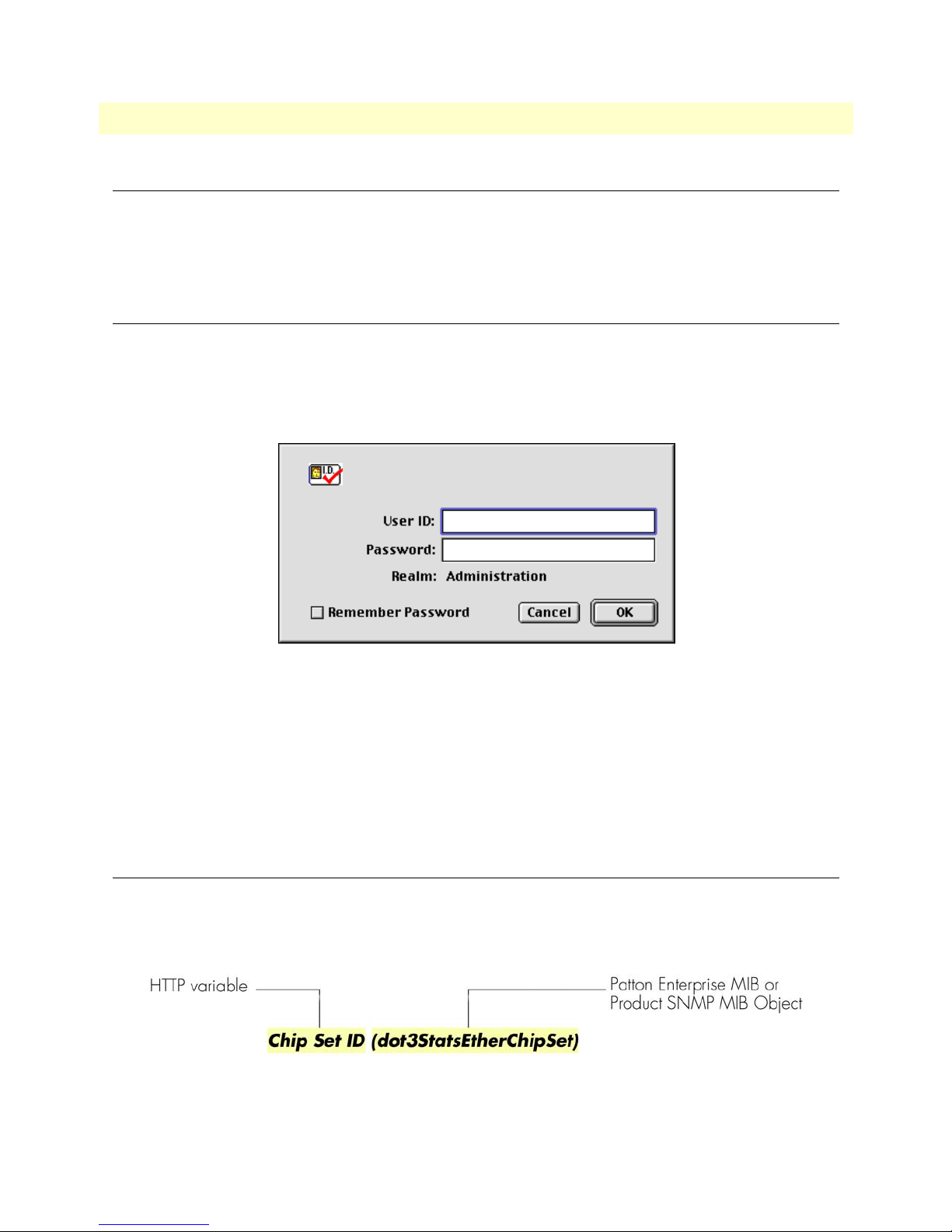
To log into the HTTP/HTML Administration pages, you must enter the 4-octet Internet Protocol (IP) (for
example, http://your.server.ip.address) address as the Universal Resource Locator (URL) into a World-Wide Web
(WWW) browser. After you enter the IP address, the access server will ask for your user name and password as
shown in
figure 1.
-
Figure 1. Access server login window
Your access server will accept the following default administrative passwords:
• superuser—this password carries full permission to change and view any parameters in the access server
• monitor—this password allows full viewing of any non-password oriented variables.
Note
For security reasons, we recommend that you change these passwords immediately after initial configuration.
HTTP/HTML and SNMP Object Format
In this document, we shall describe the variables found on each of the internal HTTP/HTML pages. This
description will include brief definitions of the Patton Enterprise MIB or SNMP MIB II object identifiers
wherever applicable. The format of the variables will resemble
Figure 2. HTTP/HTML and SNMP object format
figure 2.
Introduction 13
Page 14

Access Server Administrators’ Reference Guide 1 • Introduction
Saving HTTP/HTML Object Changes
Sometimes you will need to save changes that you have made in the HTTP/HTML pages. Do the following to
make changes to read/write variables:
1. Select the appropriate
Modify
screen.
2. Make changes to the desired parameter.
3. Click on the
4. Return to the
5. Click on the
Note
Submit
Record Current Configuration
HOME
button.
screen.
Make sure you follow steps 1 through 5 when modifying the HTTP/HTML
pages. Otherwise, your changes will be lost when the access server is powercycled.
button.
Saving HTTP/HTML Object Changes 14
Page 15

Chapter 2 Home
Chapter contents
Introduction..........................................................................................................................................................16
Operating Status Variables ....................................................................................................................................17
Active Calls (diActive) .....................................................................................................................................17
Peak Active Calls (diMaxActive) .....................................................................................................................17
Total Calls (diTotalCallAttempts) ...................................................................................................................17
DSPs Not Working (dspFailed) ......................................................................................................................17
Total DRAM Detected (boxDetectedMemory) ..............................................................................................17
Running Since Last Boot (sysUpTime) ...........................................................................................................17
Immediate Actions ................................................................................................................................................18
15
Page 16
Access Server Administrators’ Reference Guide 2 • Home
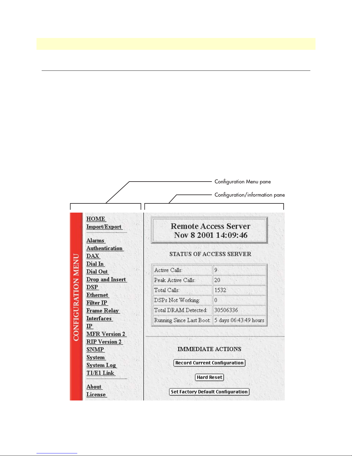
Introduction
This chapter describes the
access server (see
figure 3). From
HOME
window—the first
HOME
, you can monitor current system status, modify the Static User data-
Administration Page
that you see after logging into the
base, save any system changes, or reset the system without power-cycling the server.
Note
The
HOME
tion pane (see figure 3). The
Clicking on the
to the
HOME
HOME
link in the
page from any other page.
window is divided into two panes: the
Configuration Menu
Configuration Menu
Configuration Menu
pane will return you
pane and the configuration/informa-
contains the links to the various access server subsystems,
while the configuration/information pane is where you can view status and other information, or make changes
to the system configuration. Unlike the Configuration Menu pane, which looks the same no matter which sub
system page you may move to, the configuration/information pane contents will change as you move from one
subsystem page to another.
-
Introduction 16
Figure 3. HOME page
Page 17
Access Server Administrators’ Reference Guide 2 • Home
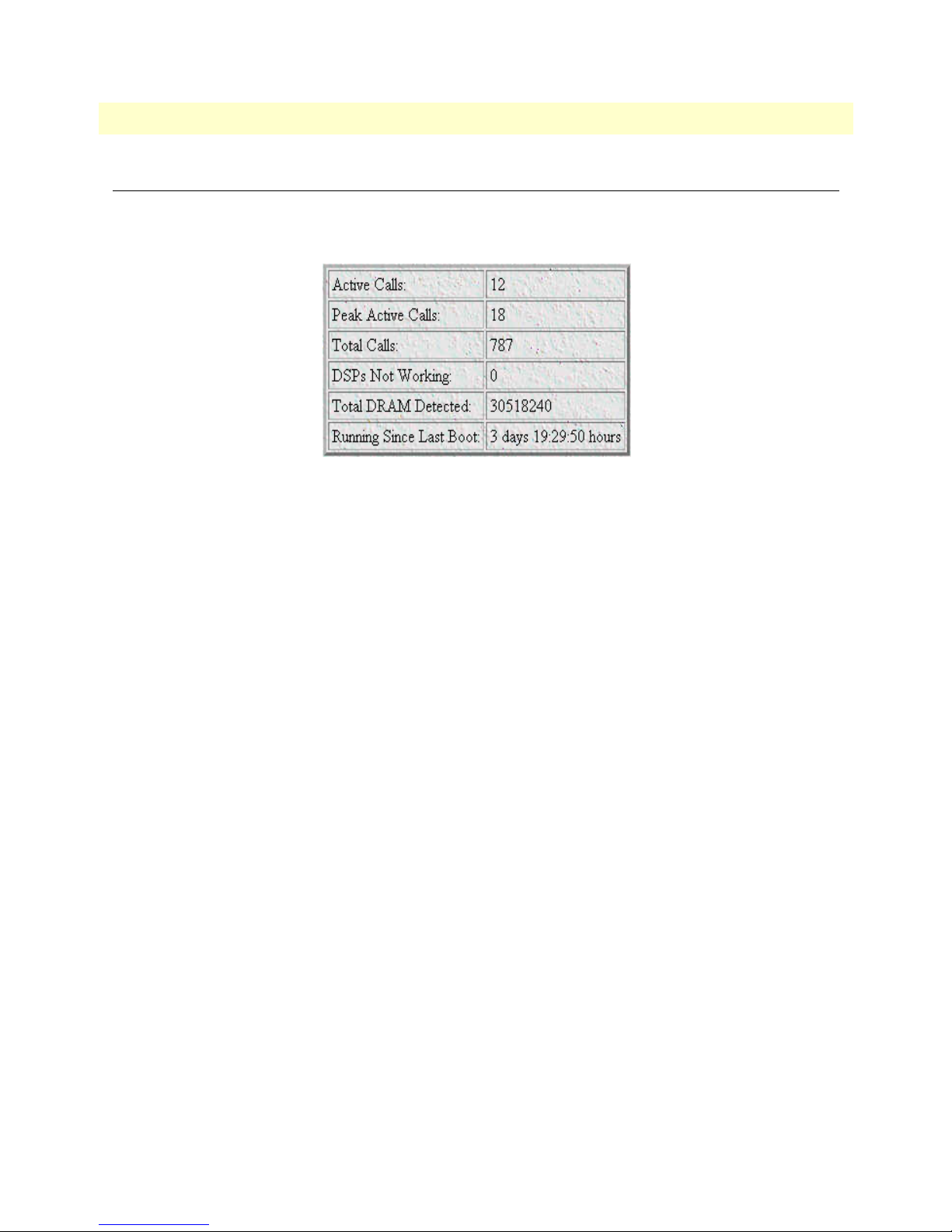
Operating Status Variables
There are seven system variables which describe the immediate operating status access server. These variables
are shown in
Active Calls (diActive)
This number, ranging from 0 to 120 displays the total number of calls being processed (connecting, online,
authenticating, and so on) in the access server at the time the HOME page was displayed.
figure 4 and are described in the following sections.
Figure 4. STATUS menu
Peak Active Calls (diMaxActive)
The maximum number of active calls seen at one time since the access server was powered on.
Total Calls (diTotalCallAttempts)
The total number of calls attempted since the last boot of the box.
DSPs Not Working (dspFailed)
This number should always be zero. The DSPs in the access server are arranged as a resource pool and called
upon at ring-time. If a DSP fails to respond to the access server’s CPU, it is determined to have failed, at which
point the CPU will remove the DSP from the resource pool. If an incoming call attempts to access the failed
DSP, the RAS will answer, then terminate the call (to a person monitoring the failed call through a telephone
handset, he or she will hear only silence during the call, ending with a faint click as the call is terminated). One
symptom indicating that a DSP has failed is if the access server is not handling as many calls as it normally does.
Total DRAM Detected (boxDetectedMemory)
This number shows the total number of bits of installed and available DRAM.
Running Since Last Boot (sysUpTime)
This tells you how long the access server has been running since the it was last reset. It displays the number of
hours and rolls over after 1,193 hours (497 days).
Operating Status Variables 17
Page 18

Access Server Administrators’ Reference Guide 2 • Home
Immediate Actions
There are several immediate actions (see figure 5) which, when in superuser mode, will cause the access server
to operate according to the descriptions in the following sections.
Figure 5. Immediate Actions buttons
•
Record Current Configuration
FLASH memory. Any changes made to the access server configuration are stored in non-volatile RAM. This
allows the user to set the box up with a running configuration before committing it to FLASH. Configura
tion changes become permanent when you select
not stored to FLASH the next time the access server is re-booted.
—clicking this button causes the current configuration to be stored in
Record Current Configuration
. You will lose all changes
-
•
Hard Reset
—this button causes the access server to perform a cold restart. When you select
Hard Reset
access server confirm that you want to execute this command. Then, the access server will disconnect all
current sessions, re-initialize the interfaces, and re-load configuration parameters from FLASH.
•
Set Factory Default Configuration
—this button clears out the configuration in FLASH and loads the factory default parameters into FLASH memory. The factory default settings will not execute on the access
server until it is re-booted.
Note Set Factory Default Configuration
will delete any routing information, the
access server’s Ethernet IP address, and any other site specific settings made
for your particular installation. You will have to re-enter the access server’s
Ethernet IP address and netmask using the front panel control port in order
to use the HTTP/HTML Management pages.
, the
Immediate Actions 18
Page 19

Chapter 3 Import/Export
Chapter contents
Introduction..........................................................................................................................................................20
Export Configuration ............................................................................................................................................20
Import Configuration............................................................................................................................................22
19
Page 20
Access Server Administrators’ Reference Guide 3 • Import/Export
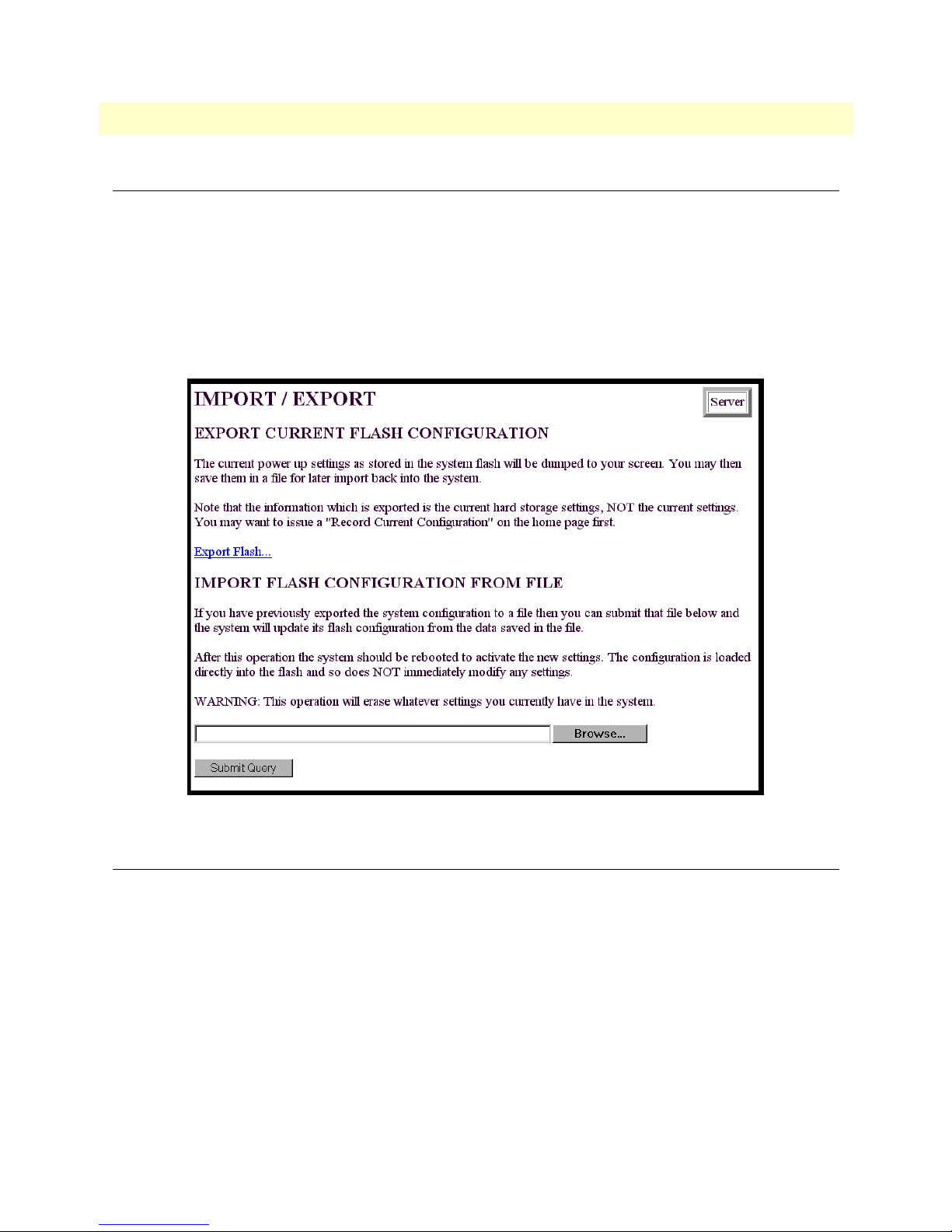
Introduction
The Import/Export function enables you to make a backup (or export) copy of your access server’s configuration parameters. By exporting the configurations, the saved files can quickly be loaded, or imported, into a
replacement access server—greatly speeding up the installation process should an access server need replacing.
Note
All actions for Import/Export require superuser access privileges.
To import or export a configuration, click on
Import/Export
main window (see figure 6).
Import/Export
under the
Configuration Menu
to display the
Export Configuration
Note
Note
Introduction 20
The exported configuration file is a text-format file. Do not try, however to
edit the operating characteristics contained in the file.
The parameters that will be exported are the power-up settings as they are
stored in flash memory and may not be the current operating parameters. To
ensure that you export the most current parameters, go to
on the
Record Current Configuration
Figure 6. Import/Export main window
button under
Immediate Actions
HOME
, then click
.
Page 21

Access Server Administrators’ Reference Guide 3 • Import/Export
To export the flash configuration, click on the
Export Flash
link on the
Import/Export
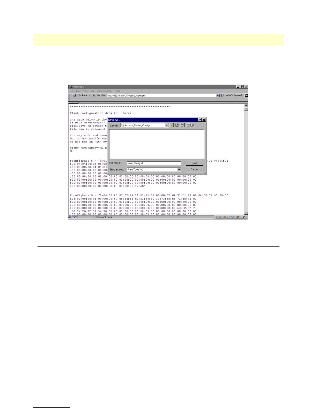
server will display text configuration information resembling that shown in
Figure 7. Typical access server flash memory configuration data
main page. The access
figure 7.
Export Configuration 21
Page 22
Access Server Administrators’ Reference Guide 3 • Import/Export
To save the displayed data as a text file, select the
under Netscape, select
File
>
Save As
. A dialog box will display enabling you to save the contents of the export
Save
option on your browser (see figure 8). For example,
parameters to a text file. Select the location where you want the file stored, type a file name, and click
Save
.
Figure 8. Saving the access server flash memory configuration data as a text file
Import Configuration
To import a configuration file into the access server, type the complete path and filename for the configuration
file you wish to load or click on the
button (see
figure 6 on page 20).
Upon successfully importing the file, the access server will display Configuration Load Complete, indicating that
the new operating parameters have been loaded into flash memory.
Click on
HOME
Note
under the
Do not select
Configuration Menu
parameters.
Browse…
button to select the desired file, then click on the
, then click on the
Record Current Configuration
Hard Reset
button under
Immediate Actions
after importing configuration
Submit Query
.
Import Configuration 22
Page 23

Chapter 4 Alarms
Chapter contents
Introduction..........................................................................................................................................................24
Displaying the Alarms window ..............................................................................................................................25
Total System Alarms:X (alarmTotal) ...............................................................................................................25
Alarm Response Outputs ................................................................................................................................26
Alarm Syslog Priority (syslogAlarmPriority) ..............................................................................................26
Alarm SNMP Trap IP 1 (alarmTrapIp0) ...................................................................................................26
Alarm SNMP Trap IP 2 (alarmTrapIp1) ...................................................................................................26
Alarm SNMP Trap IP 3 (alarmTrapIp2) ...................................................................................................26
Alarm SNMP Trap IP 4 (alarmTrapIp3) ...................................................................................................26
Temperature Threshold (boxAlarmTemperature) ......................................................................................26
Current Box Temperature (boxTemperature) ............................................................................................26
Clear All Alarms ........................................................................................................................................26
Alarms ............................................................................................................................................................26
Alarm ID (alarmDefIndex) ........................................................................................................................26
Alarm Name (alarmName) ........................................................................................................................27
Alarm Severity (alarmSeverity) ..................................................................................................................27
Time Since Alarm (alarmTicks) .................................................................................................................27
Alarm Count (alarmCount) ......................................................................................................................27
Generate Alarm .........................................................................................................................................27
Clear Alarm ...............................................................................................................................................27
Modify Response—Configuring the alarm response system...................................................................................27
Alarm Syslog Priority (syslogAlarmPriority) ....................................................................................................28
Alarm SNMP Trap IP 1 (alarmTrapIp0) ........................................................................................................28
Alarm SNMP Trap IP 2 (alarmTrapIp1) ........................................................................................................28
Alarm SNMP Trap IP 3(alarmTrapIp2) .........................................................................................................28
Alarm SNMP Trap IP 4(alarmTrapIp3) .........................................................................................................28
Temperature Threshold(boxAlarmTemperature) ............................................................................................28
Modify Alarms—Configuring alarm severity levels................................................................................................29
23
Page 24

Access Server Administrators’ Reference Guide 4 • Alarms
Introduction
The access server has an extensive alarm reporting system which enables users to configure, monitor, and test
major and minor alarms. The alarm system can be set to notify if equipment fails (for example, a power supply
failure) or if a T1/E1/PRI port malfunctions. There are 11 access server items that can be configured by the
user to generate alerts based on the condition of the access server. The access server has three methods to notify
of an alarm condition:
• Front panel LED—The front panel ALARM LED has three states that indicate the presence and severity of
an alarm. The states are:
- Off—No alarm present
- Solid—Minor alarm
- Flashing—Major alarm.
• Administration web page indication—The alarms window of the administration page uses highlighting to
indicate which items are in alarm state and how critical the alarm is according to the alarm severity set (see
figure 9):
- Red—Indicates that the alarm has been designated as a critical alarm by the system administrator
- Gold—Indicates that the alarm has been designated as a major alarm by the system administrator
- Yellow—Iindicates that the alarm has been designated as a minor alarm by the system administrator
- Blue—Indicates that the alarm has informational value only as designated by the system administrator
- None—There is no alarm present or the system administrator has chosen for the alarm to be ignored
Figure 9. Sample alarm indication
Introduction 24
Page 25
Access Server Administrators’ Reference Guide 4 • Alarms
• SYSLOG/SNMP—For external notification, the access server can be configured to send a SYSLOG mes-
sage or an SNMP TRAP to an external management host. To configure the alarm response for either SNMP
Traps or SYSLOG messages, click on the
Alarm Response
link (go to “Modify Response—Configuring the
alarm response system” on page 27).
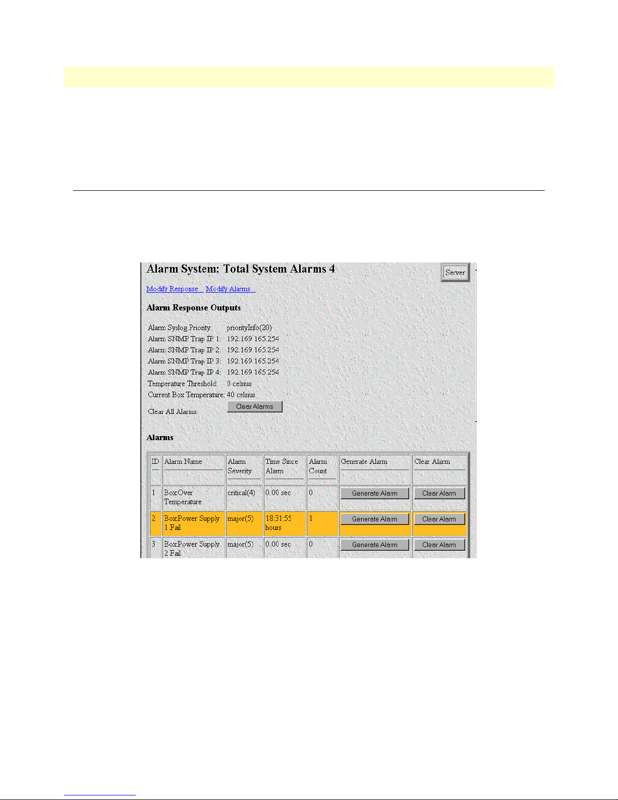
Displaying the Alarms window
Click on
Alarms
Note
under the
Configuration Menu
to display the Alarm System main window (figure 10).
The system administrator can manually generate a specific alarm for testing
purposes or clear the alarm counters from the main window.
Note
The POWER LED will flash if a power supply failure alarm is present.
Total System Alarms:X (alarmTotal)
The total number of alarms currently active on the system.
Besides enabling a user to view current alarm status, manually generate an alarm as a test, and clear the alarm
time and alarm count variables, the Alarms main window also contains links to the following:
• Modify Response—Clicking on this link takes you to a window where you can change how the SYSLOG/
SNMP function notifies remote users of an alarm (see
system” on page 27)
Displaying the Alarms window 25
Figure 10. Alarms main window
“Modify Response—Configuring the alarm response
Page 26

Access Server Administrators’ Reference Guide 4 • Alarms
• Modify Alarms—Clicking on this link takes you to a window where you can change how the access server
perceives the severity of each alarm (
“Modify Alarms—Configuring alarm severity levels” on page 29)
Alarm Response Outputs
Alarm Response Outputs display the current settings for handling alarm notification via SYSLOG/SNMP
messages. To change how the SYSLOG/SNMP function notifies remote users of an alarm, refer to
“Modify
Response—Configuring the alarm response system” on page 27.
Alarm Syslog Priority (syslogAlarmPriority)
Displays the SYSLOG priority of the alarm SYSLOG message. If the minimum priority for SYSLOG daemon
(set under the System Log link) is less than this value, the SYSLOG daemon will receive the major or critical
alarm SYSLOG message.
Alarm SNMP Trap IP 1 (alarmTrapIp0)
The IP address of a host system which is running the SNMP trap daemon. Critical and major alarm messages
will be sent to the system. If set to 0.0.0.0 then no trap message will be sent in response to a major alarm.
Alarm SNMP Trap IP 2 (alarmTrapIp1)
The IP address of a host system which is running the SNMP trap daemon. Critical and major alarm messages
will be sent to the system. If set to 0.0.0.0 then no trap message will be sent in response to a major alarm.
Alarm SNMP Trap IP 3 (alarmTrapIp2)
The IP address of a host system which is running the SNMP trap daemon. Critical and major alarm messages
will be sent to the system. If set to 0.0.0.0 then no trap message will be sent in response to a major alarm.
Alarm SNMP Trap IP 4 (alarmTrapIp3)
The IP address of a host system which is running the SNMP trap daemon. Critical and major alarm messages
will be sent to the system. If set to 0.0.0.0 then no trap message will be sent in response to a major alarm.
Temperature Threshold (boxAlarmTemperature)
If the box registers a temperature greater than this temperature an alarm will be reported. Temperature is
reported in degrees Celsius.
Current Box Temperature (boxTemperature)
Displays the current temperature in Celsius.
Clear All Alarms
Clicking on this button resets all alarms to a non-alarm condition. Clear All Alarms does the following for all
alarms: it resets the alarm, resets Alarm Time to 0.0 seconds, and resets the Alarm Count to 0.
Alarms
This portion of the Alarms main window displays the alarm status table, where you can view current alarm status, manually generate an alarm as a test, and clear the alarm time and alarm count variables.
Alarm ID (alarmDefIndex)
This number identifies the alarm item.
Displaying the Alarms window 26
Page 27
Access Server Administrators’ Reference Guide 4 • Alarms
Alarm Name (alarmName)
The alarm items are grouped into two categories: Box and WAN trunk alarms. The Box group category lists
access server temperature and power supply status. The WAN category monitors the T1/E1/PRI ports for yel
low and red alarms.
Alarm Severity (alarmSeverity)
Shows the alarm severity selected by the system administrator.
Time Since Alarm (alarmTicks)
The
Alarm Time
column displays the number of seconds the alarm has been activated.
Alarm Count (alarmCount)
The
Alarm Count
column indicates how many times the alarm has occurred since the last time alarms were
cleared. It is a useful tool for monitoring self-clearing alarms.
Generate Alarm
For testing purposes, clicking the
Generate Alarm
button next to each alarm name will cause that alarm condi-
tion to be activated, as if the actual alarm trigger had occurred.
-
Clear Alarm
Clicking the
Clear Alarm
button resets the alarm to a non-alarm condition. Clear Alarm resets Alarm Time to
0.0 seconds, and resets the Alarm Count to 0.
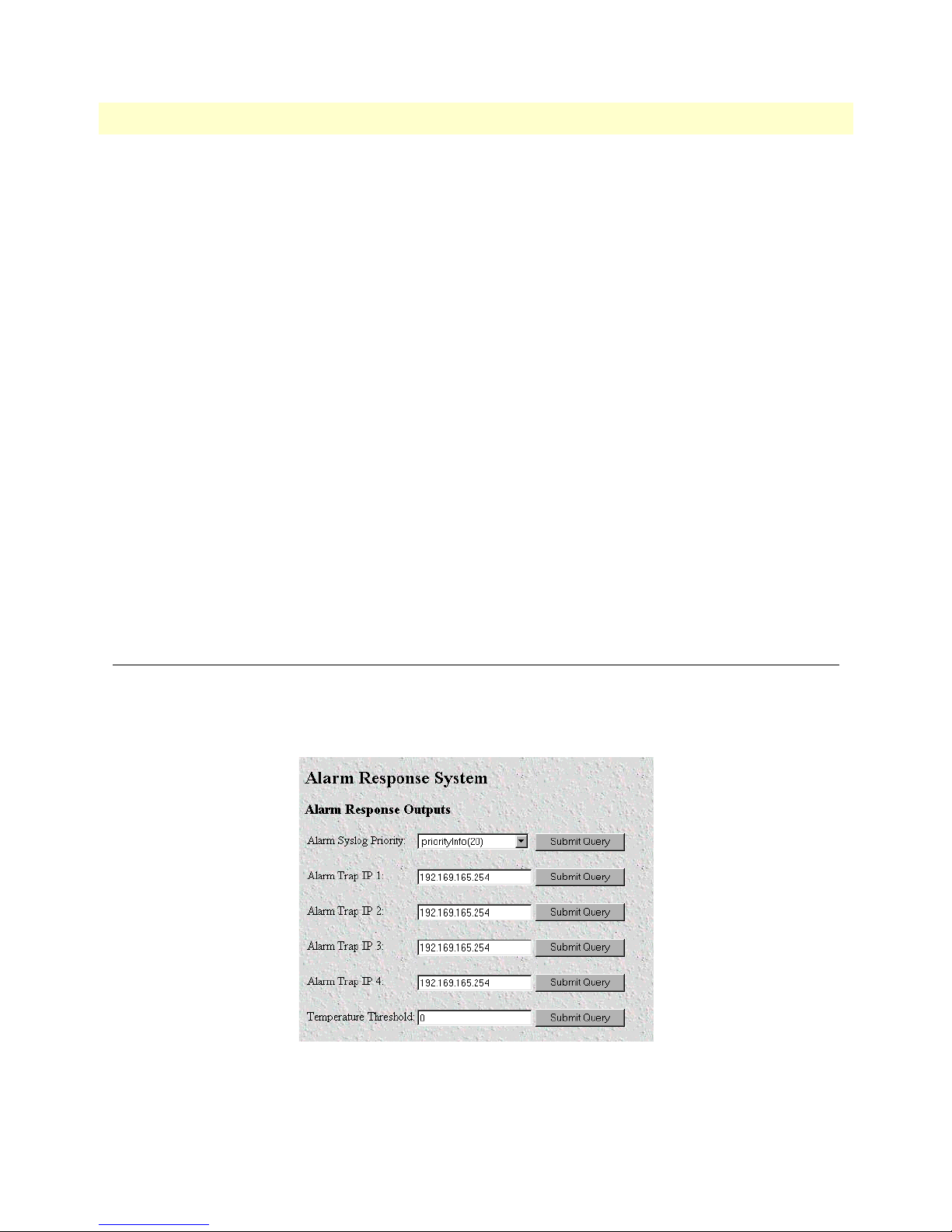
Modify Response—Configuring the alarm response system
The alarm response outputs only effect external notification via SYSLOG/SNMP as the front panel ALARM
LED and the web administration pages will always indicate an alarm condition. The following user configura
tion items can be set to permit external notification of access server alarm conditions:
-
Modify Response—Configuring the alarm response system 27
Figure 11. Alarm Response System window
Page 28

Access Server Administrators’ Reference Guide 4 • Alarms
Alarm Syslog Priority (syslogAlarmPriority)
The SYSLOG priority of the alarm SYSLOG message. If the minimum priority for SYSLOG daemon (set
under the System Log link) is less than this value, the SYSLOG daemon will receive the major or critical alarm
SYSLOG message (prioritySystem has the highest priority; priorityVerbose the lowest).
• priorityVerbose(5)
• priorityDebug(10)
• priorityInfo(20)
• priorityOddity(40)
• priorityService(60)
• prioritySystem(80)
• priorityDisable(1000)
• priorityDisable(1000)
Alarm SNMP Trap IP 1 (alarmTrapIp0)
The IP address of a host system which is running the SNMP trap daemon. Critical and major alarm messages
will be sent to the system. If set to 0.0.0.0 then no trap message will be sent in response to a major alarm.
Alarm SNMP Trap IP 2 (alarmTrapIp1)
The IP address of a host system which is running the SNMP trap daemon. Critical and major alarm messages
will be sent to the system. If set to 0.0.0.0 then no trap message will be sent in response to a major alarm.
Alarm SNMP Trap IP 3(alarmTrapIp2)
The IP address of a host system which is running the SNMP trap daemon. Critical and major alarm messages
will be sent to the system. If set to 0.0.0.0 then no trap message will be sent in response to a major alarm.
Alarm SNMP Trap IP 4(alarmTrapIp3)
The IP address of a host system which is running the SNMP trap daemon. Critical and major alarm messages
will be sent to the system. If set to 0.0.0.0 then no trap message will be sent in response to a major alarm.
Temperature Threshold(boxAlarmTemperature)
If the box registers a temperature greater than this temperature an alarm will be reported. Temperature is in
degrees Celsius.
Modify Response—Configuring the alarm response system 28
Page 29
Access Server Administrators’ Reference Guide 4 • Alarms
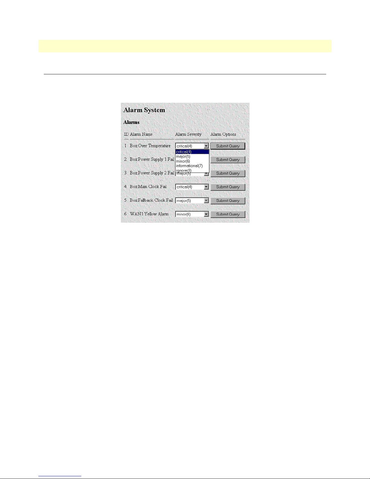
Modify Alarms—Configuring alarm severity levels
The Modify Alarms window (see figure 12) is where you can set the severity level each alarm condition gener-
ates and whether it can be a self-clearing condition.
Figure 12. Modify Alarms settings window
The following alarm items that can be configured to generate alarm conditions:
• Box: Over Temperature—An alarm will be triggered when the current temperature exceeds the temperature
threshold.
• Box: Power Supply 1–2 Fail—An alarm will be triggered if power supply 1 or 2 fails.
• Box: Main and Fallback Clock Fail—An alarm will be triggered when either the main or fallback clock fail.
• WAN 1–4 Yellow Alarm—When a WAN port detects a yellow alarm condition, the specific WAN alarm
will be set.
• WAN 1–4 Red Alarm—When a WAN port detects a red alarm condition, the specific WAN alarm will be set.
Each alarm item can be set for one of the following severity levels:
• Critical(4)
• Major(5)
• Minor(6)
• Informational(7)
• Ignore(8)
Note
For maximum flexibility, defining the severity level of the alarm is left up to
the administrator. To set an alarm, click on the drop-down menu for the
desired alarm item, choose the new setting, then click on
Submit Query
.
Modify Alarms—Configuring alarm severity levels 29
Page 30

Chapter 5 Authentication
Chapter contents
Introduction..........................................................................................................................................................32
Displaying the Authentication window..................................................................................................................32
The Statistics section .............................................................................................................................................32
Validated authentications (auAuthenticationsValidTotal) ...............................................................................32
Validated via primary server (auAuthenticationsValidPrimary) .......................................................................32
Validated via secondary server (auAuthenticationsValidSecondary) .................................................................32
Validated via static database (auAuthenticationsValidStatic) ...........................................................................33
Denied authentications (auAuthenticationsDenied) ........................................................................................33
Primary server retries (auPrimaryServerRetrys) ................................................................................................33
Secondary server retries (auSecondaryServerRetrys) .........................................................................................33
Accounting server retries (auAccountingServerRetrys) .....................................................................................33
Primary server timeouts (auPrimaryServerTimeouts) ......................................................................................33
Secondary server timeouts (auSecondaryServerTimeouts) ...............................................................................33
Accounting server timeouts (auAccountingServerTimeouts) ...........................................................................33
Maximum Response Time ..............................................................................................................................33
Last Response Time ........................................................................................................................................33
The Configuration section.....................................................................................................................................34
Validation (auValidation) ...............................................................................................................................34
Host Address (auHostAddress) ........................................................................................................................35
Secondary Host Address (auSecondaryHostAddress) .......................................................................................35
Host Port (auHostPort) ..................................................................................................................................35
Timeout (auTimeout) .....................................................................................................................................35
Retries (auRetries) ...........................................................................................................................................35
Secret (auSecret) .............................................................................................................................................35
NAS Identifier (auNASIdentifier) ...................................................................................................................35
Accounting Address (auAcctAddress) ..............................................................................................................35
Secondary Accounting Address (auSecondaryAcctAddress) .............................................................................35
Accounting Port (auAcctPort) .........................................................................................................................36
Accounting Enable (auAccountingEnable) ......................................................................................................36
Radius Packet Format (auRadiusPacketFormat) ..............................................................................................36
Radius Session ID Size (auRadiusRunningIdSize) ...........................................................................................36
Radius Session ID (auRadiusRunningId) ........................................................................................................37
Setting Up Authentication.....................................................................................................................................37
Validation (auValidation) ...............................................................................................................................38
Host Address (auHostAddress) ........................................................................................................................39
Secondary Host Address (auSecondaryHostAddress) .......................................................................................39
Host Port (auHostPort) ..................................................................................................................................39
Timeout (auTimeout) .....................................................................................................................................39
Retries (auRetries) ...........................................................................................................................................39
30
Page 31

Access Server Administrators’ Reference Guide 5 • Authentication
Secret (auSecret) .............................................................................................................................................39
NAS Identifier (auNASIdentifier) ...................................................................................................................39
Accounting Address (auAcctAddress) ..............................................................................................................39
Secondary Accounting Address (auSecondaryAcctAddress) .............................................................................39
Accounting Port (auAcctPort) .........................................................................................................................40
Accounting Enable (auAccountingEnable) ......................................................................................................40
Radius Packet Format (auRadiusPacketFormat) ..............................................................................................40
Radius Session ID Size (auRadiusRunningIdSize) ...........................................................................................40
Static User Authentication.....................................................................................................................................41
Adding Static Users ...............................................................................................................................................41
ID (suID) .......................................................................................................................................................41
Username (suUsername) .................................................................................................................................41
Password (suPassword) ....................................................................................................................................41
Service (suService) ...........................................................................................................................................41
Modify Static User ................................................................................................................................................42
Service IP (suServiceIP) ...................................................................................................................................43
Service Port (suServicePort) ............................................................................................................................43
Service Mask (suServiceMask) .........................................................................................................................43
Filter ID (suFilterId) .......................................................................................................................................43
31
Page 32

Access Server Administrators’ Reference Guide 5 • Authentication
Introduction
Use the
Authentication
pages to set up system security and to provide specific users with access to appropriate
network services. This section describes the authentication parameters. The access server uses static and/or
RADIUS authentication to decide which dial-in users can access the system (refer to
A, “Supported RADIUS
Attributes” on page 300 for a full list of RADIUS attributes).
Displaying the Authentication window
Do the following:
1. Click on
Authentication
under the
Configuration Menu
(see figure 13).
Figure 13. Authentication main screen (Statistics section)
2. Select
Modify
to set up or change access server Authentication parameters.
The Statistics section
The Statistics section of the main
User logins gathered since the last access server reset.
Validated authentications (auAuthenticationsValidTotal)
The total number of validated authentications since the last access server reset.
Validated via primary server (auAuthenticationsValidPrimary)
The number of authentications validated by the primary RADIUS authentication server since the last access
server reset.
Validated via secondary server (auAuthenticationsValidSecondary)
The number of authentications validated by the secondary RADIUS authentication server since the last access
server reset.
Introduction 32
Authentication
screen lists running totals of statistics for RADIUS and Static
Page 33

Access Server Administrators’ Reference Guide 5 • Authentication
Validated via static database (auAuthenticationsValidStatic)
The number of authentications validated by the Static User database since the last access server reset.
Denied authentications (auAuthenticationsDenied)
The total number of authentication attempts requested but denied since the last access server reset.
Primary server retries (auPrimaryServerRetrys)
The number of times the access server needed to make subsequent requests for a call to the primary RADIUS
authentication server.
Secondary server retries (auSecondaryServerRetrys)
The number of times the access server needed to make subsequent requests for a call to the secondary RADIUS
authentication server.
Accounting server retries (auAccountingServerRetrys)
The number of times the access server needed to make subsequent accounting requests for a call.
Primary server timeouts (auPrimaryServerTimeouts)
The total number of authentication timeouts by the primary RADIUS authentication server.
Secondary server timeouts (auSecondaryServerTimeouts)
The total number of authentication timeouts by the secondary RADIUS authentication server.
Accounting server timeouts (auAccountingServerTimeouts)
The total number of accounting timeouts by the primary RADIUS accounting server.
Maximum Response Time
The maximum time it has taken for authentication to be completed since the server rebooted.
Last Response Time
The time taken for the last authentication to be completed.
The Statistics section 33
Page 34

Access Server Administrators’ Reference Guide 5 • Authentication
The Configuration section
The configuration section of the main
Authentication
screen (see figure 14) shows how the authentication
method used by the RAS is configured.
Figure 14. Authentication main screen (Configuration section)
Validation (auValidation)
Selects how the access server will authenticate an incoming call. Select from:
• No Validation(0)—Select this to allow un-authenticated calls into the access server, and on to your LAN,
using the default service.
• static Users(1)—Use the access server internal user database only to authenticate. Static users are simply
users and passwords entered into the access server’s internal users database.
• radius Users(2)—Use RADIUS to authenticate and provision user services. RADIUS is a client-server sys-
tem developed to manage the flexible requirements of remote dial-in users. The RADIUS protocol is specified under RFC 2138 for authentication and RFC 2139 for accounting. RADIUS servers are available as
freeware for most computer platforms and is an excellent method for managing user dial-in security. Any
RADIUS entries will require an associated server to process authentication requests from the access server or
the access server will reject users access. For more information about RADIUS, see RADIUS User Authen
tication, below.
• tacacs Users(3)—This feature is not currently available
• static Then RADIUS(4)—Check the internal user database first, if no match is found, then use RADIUS to
authenticate and provision user services.
• static Then Tacacs(5)— Check the internal user database first, if no match is found, then use TACACS to
authenticate and provision user services. Not currently implemented.
Note
The following options apply only when using an external authentication
server.
-
The Configuration section 34
Page 35

Access Server Administrators’ Reference Guide 5 • Authentication
Host Address (auHostAddress)
Tells the access server the IP address of the primary external authentication server. This must be the IP address
as the access server will not resolve a Fully Qualified Domain Name.
Secondary Host Address (auSecondaryHostAddress)
When using a remote authentication server (RADIUS) this variable provides an alternative server IP address.
Host Port (auHostPort)
This variable tells the access server which UDP port to use when connecting to the host specified in the Host
Address variable. The RADIUS standard, as per RFC 2138, specifies port 1812 for RADIUS authentication.
Some older installations of RADIUS use port 1645.
Timeout (auTimeout)
This option specifies the time, in seconds, before the access server will retransmit an authentication request to
an external authentication server.
Retries (auRetries)
This option specifies the number of times the access server will resend an authentication request to a RADIUS
server after a TIMEOUT occurs. If this number is exceeded then the secondary host will be tried. If this num
ber is exceeded by the secondary host, the user will be rejected.
-
Secret (auSecret)
The Secret variable sets the shared secret between the authentication client (access server) and the authentication server (RADIUS). It is used to encrypt an authentication request and to decrypt an incoming reply from
the server. The secret on the access server and the RADIUS server must match and must be 15 or fewer print
able, non space, ASCII characters.
Note
The same secret word must used on the access server and in the RADIUS clients file.
NAS Identifier (auNASIdentifier)
This variable is used to identify the access server to the remote authentication server. If this option is blank,
then the access server will use it’s IP address to identify itself to the remote server. It does this by using the
NAS-IP-Address attribute instead of the NAS-Identifier attribute.
Accounting Address (auAcctAddress)
This is the IP address of the accounting server. RADIUS also allows for the recording of accounting information.
Secondary Accounting Address (auSecondaryAcctAddress)
When using a remote accounting server (such as RADIUS Accounting) this variable provides the IP address of
the accounting server.
-
The Configuration section 35
Page 36

Access Server Administrators’ Reference Guide 5 • Authentication
Accounting Port (auAcctPort)
This is the UDP port on the accounting server specified in Acct Address that the access server should use to
transfer accounting information. RFC 2139 states that port 1813 is the standard RADIUS accounting port.
Some older implementations of RADIUS use port 1646 as the accounting port.
Accounting Enable (auAccountingEnable)
This is a switch that allows the enabling or disabling the reporting of accounting information on the access
server. The following options are available:
• enableAccounting—Begin accounting of RADIUS authenticated users.
• disableAccounting—Disable the accounting feature.
• enableAccounting-no validation—When a response is received from either the authentication or the
accounting server it is validated using the defined secret. If the secret does not match, the reply packet is
dropped just as if it never existed.
Early versions of the Livingston RADIUS server used a method for encoding the accounting reply packet
that was incorrect. Accounting replies from these servers would therefore be dropped because they could
not be authenticated, eventually resulting in timeouts and shutting the call down with the reason authenAc
countingTimeout. As a workaround for this issue, the state enableAccountingNoValidation—which does not
check for valid encoding on the accounting reply packet—was added as an option.
-
Radius Packet Format (auRadiusPacketFormat)
The following options are available:
• fullRfcPacket—The accept request packet includes Calling-Station-Id and Service-Type RADIUS
attributes.
• minimumRfcPacket—This setting does not include Calling-Station-Id and Service-Type RADIUS
attributes.
Radius Session ID Size (auRadiusRunningIdSize)
The session ID—which is sent in the Accounting start and stop packets—can be configured as either an 8 or
12-character string.
Figure 15. 8-Character String RADIUS Session ID format
The 8-character session ID is formatted as follows (see figure 15):
• MM—The last two digits of the MAC address
• R—The number of times the RAS has rebooted since the last code upload. This rolls over to 0 after 10
reboots
The Configuration section 36
Page 37

Access Server Administrators’ Reference Guide 5 • Authentication
• CCCCC—Call ID in hex. The call ID used is the one recorded on the main dial-in screen.
Figure 16. 12-Character String RADIUS Session ID format
The 12-character session ID is formatted as follows (see figure 16):
• MMMM—The last four digits of the MAC address
• RR—The number of times the RAS has rebooted since the last code upload. This rolls over to 0 after 100
reboots
• S—Not used.
• CCCCC—Call ID in hex. The call ID used is the one recorded on the main dial-in screen.
Radius Session ID (auRadiusRunningId)
The RADIUS session ID shows the identifier—created anew each time power is cycled on and off. The ID is
prepended onto the call ID to create the session ID that is sent to the RADIUS server.
Setting Up Authentication
After selecting
ters for both RADIUS users and Static users. After configuring the Validation method (see “Validation
Modify
from the main
Authentication
screen, you may set up or change authentication parame-
Setting Up Authentication 37
Page 38

Access Server Administrators’ Reference Guide 5 • Authentication
(auValidation)” below), configure the additional parameters as shown in figure 17 to configure RADIUS
parameters. See “Static User Authentication” on page 41 to set up Static users.
Figure 17. Authentication Configuration screen
Validation (auValidation)
Selects how the access server will authenticate an incoming call. Select from:
• No Validation(0)—Select this to allow un-authenticated calls into the access server, and on to your LAN,
using the default service.
• static Users(1)—Use the access server internal user database only to authenticate. Static users are simply
users and passwords entered into the access server’s internal users database.
• radius Users(2)—Use RADIUS to authenticate and provision user services. RADIUS is a client-server sys-
tem developed to manage the flexible requirements of remote dial-in users. The RADIUS protocol is specified under RFC 2138 for authentication and RFC 2139 for accounting. RADIUS servers are available as
freeware for most computer platforms and is an excellent method for managing user dial-in security. Any
RADIUS entries will require an associated server to process authentication requests from the access server or
the access server will reject users access. For more information about RADIUS, see RADIUS User Authen
tication, below.
• tacacs Users(3)—This feature is not currently available
• static Then RADIUS(4)—Check the internal user database first, if no match is found, then use RADIUS to
authenticate and provision user services.
• static Then Tacacs(5)— Check the internal user database first, if no match is found, then use TACACS to
authenticate and provision user services. Not currently implemented.
-
Note
The following options apply only when using an external authentication
server.
Setting Up Authentication 38
Page 39

Access Server Administrators’ Reference Guide 5 • Authentication
Host Address (auHostAddress)
Tells the access server the IP address of the primary external authentication server. This must be the IP address
as the access server will not resolve a Fully Qualified Domain Name.
Secondary Host Address (auSecondaryHostAddress)
When using a remote authentication server (RADIUS) this variable provides an alternative server IP address.
Host Port (auHostPort)
This variable tells the access server which UDP port to use when connecting to the host specified in the Host
Address variable. The RADIUS standard, as per RFC 2138, specifies port 1812 for RADIUS authentication.
Some older installations of RADIUS use port 1645.
Timeout (auTimeout)
This option specifies the time, in seconds, before the access server will retransmit an authentication request to
an external authentication server.
Retries (auRetries)
This option specifies the number of times the access server will resend an authentication request to a RADIUS
server after a TIMEOUT occurs. If this number is exceeded then the secondary host will be tried. If this num
ber is exceeded by the secondary host, the user will be rejected.
-
Secret (auSecret)
The Secret variable sets the shared secret between the authentication client (access server) and the authentication server (RADIUS). It is used to encrypt an authentication request and to decrypt an incoming reply from
the server. The secret on the access server and the RADIUS server must match and must be 15 or fewer print
able, non space, ASCII characters.
Note
The same secret word must used on the access server and in the RADIUS clients file.
NAS Identifier (auNASIdentifier)
This variable is used to identify the access server to the remote authentication server. If this option is blank,
then the access server will use it’s IP address to identify itself to the remote server. It does this by using the
NAS-IP-Address attribute instead of the NAS-Identifier attribute.
Accounting Address (auAcctAddress)
This is the IP address of the accounting server. RADIUS also allows for the recording of accounting information.
Secondary Accounting Address (auSecondaryAcctAddress)
When using a remote accounting server (such as RADIUS Accounting) this variable provides the IP address of
the accounting server.
-
Setting Up Authentication 39
Page 40

Access Server Administrators’ Reference Guide 5 • Authentication
Accounting Port (auAcctPort)
This is the UDP port on the accounting server specified in Acct Address that the access server should use to
transfer accounting information. RFC 2139 states that port 1813 is the standard RADIUS accounting port.
Some older implementations of RADIUS use port 1646 as the accounting port.
Accounting Enable (auAccountingEnable)
This is a switch that allows the enabling or disabling the reporting of accounting information on the access
server. The following options are available:
• enableAccounting—Begin accounting of RADIUS authenticated users.
• disableAccounting—Disable the accounting feature.
• enableAccounting-no validation—When a response is received from either the authentication or the
accounting server it is validated using the defined secret. If the secret does not match, the reply packet is
dropped just as if it never existed.
Early versions of the Livingston RADIUS server used a method for encoding the accounting reply packet
that was incorrect. Accounting replies from these servers would therefore be dropped because they could
not be authenticated, eventually resulting in timeouts and shutting the call down with the reason authenAc
countingTimeout. As a workaround for this issue, the state enableAccountingNoValidation—which does not
check for valid encoding on the accounting reply packet—was added as an option.
-
Radius Packet Format (auRadiusPacketFormat)
The following options are available:
• fullRfcPacket—The accept request packet includes Calling-Station-Id and Service-Type RADIUS
attributes.
• minimumRfcPacket—This setting does not include Calling-Station-Id and Service-Type RADIUS
attributes.
Radius Session ID Size (auRadiusRunningIdSize)
The session ID—which is sent in the Accounting start and stop packets—can be configured as either an 8 or
12-character string.
The 8-character session ID is formatted as follows (see figure 15 on page 36):
• MM—The last two digits of the MAC address
• R—The number of times the RAS has rebooted since the last code upload. This rolls over to 0 after 10
reboots
• CCCCC—Call ID in hex. The call ID used is the one recorded on the main dial-in screen.
The 12-character session ID is formatted as follows (see figure 16 on page 37):
• MMMM—The last four digits of the MAC address
• RR—The number of times the RAS has rebooted since the last code upload. This rolls over to 0 after 100
reboots
• S—Not used.
• CCCCC—Call ID in hex. The call ID used is the one recorded on the main dial-in screen.
Setting Up Authentication 40
Page 41

Access Server Administrators’ Reference Guide 5 • Authentication
Static User Authentication
To view or modify the static users in the internal user database, click on
Menu
. The
Authentication
window displays. Scroll down until
Static User Identification
Authentication
in the
Configuration
is displayed (see
figure 18).
Static users consist of usernames and passwords entered into the access server’s internal users database. You can
have up to 111 static users in the access server database.
You must have superuser-level access to make changes to the static users database.
The following sections describe each of the variables found in the
Static User Identification
section.
Figure 18. Static User Identification setup
Adding Static Users
ID (suID)
Identifies the entry in the table of users. For the next user, select the next unused number. If you select a number that is already displayed in the Static User Identification table, you will overwrite a current entry in user
database.
Username (suUsername)
This is a unique name, to be provided at login time.
Note
Password (suPassword)
This is the password that is provided at login time along with the username.
Service (suService)
This option instructs the access server on how to service the incoming call. Select from:
• default—This is the default service as specified under Dial-In (see 7, “Dial In” on page 48). We recommend
that you select default.
There is a 19-character limit on the username length.
Static User Authentication 41
Page 42

Access Server Administrators’ Reference Guide 5 • Authentication
• admin—Not currently implemented.
• monitor—Not currently implemented.
• rlogin—Causes the access server to rlogin into another host. See “Service IP (suServiceIP)” on page 43 for
information on configuring the remote host IP addresss.
• telnet—Causes the access server to telnet into another host.
• tcpraw—All 8 bits are passed unchecked and unaltered.
• ppp—Access server will try to negotiate a PPP session.
• cppp—Access server will try to negotiate a Compressed-PPP session.
Note
If a user attempts to login in using a different service than the one he or she
has been provided, the access server will reject the user. The exception to this
is CPPP which will revert to PPP if CPPP is not available on the client.
• slip—Access server will negotiate a SLIP connection. Not currently implemented.
• cslip—Access server will negotiate a Compressed-SLIP connection. Not currently implemented.
• dialout—Access server will give a dialout connection. The dialout connection is an AT command set driven
connection into one of the access server modems. On line help is provided by typing at help <cr>.
• vpn—This option is currently not supported.
Note
If a user attempts to login in using a different service than the one he or she
has been provided, the access server will reject the user. The exception to this
is CPPP which will revert to PPP if CPPP is not available on the client.
Note
All changes made to the running configuration must be saved to FLASH by
selecting
HOME
Record Current Configuration
under
Immediate Actions
on the
page of the access server. Failure to do so will cause all configuration
information to be lost the next time the access server is re-booted.
After the user information has been entered, click
Submit
.
Modify Static User
To modify or further configure the user, click the username you just created to display the
(see
figure 19). Refer to the following sections while modifying the Static User settings. When you are finished,
click
Submit
Modify Static User 42
to store the changes.
Static User
window
Page 43

Access Server Administrators’ Reference Guide 5 • Authentication
Figure 19. Static User settings window
Service IP (suServiceIP)
This is the IP of the RLogin or Telnet host, or the static IP address assigned to the user. This is determined by
the option selected in
Service
(see “Service (suService)” on page 41).
Service Port (suServicePort)
This is the port number to connect to the service host. If the number is 0, the access server will use the default
values for Telnet (port number 23) and RLogin (port number 513).
Note
After you have submitted all changes, click on the
uration Menu
ton (located under
memory on the access server.
. Once there, click on the
Immediate Actions
Record Current Configuration
) to save the changes to FLASH
HOME
link in the
Config-
but-
All changes made to the running configuration must be saved to FLASH
memory. Failure to do so will cause all configuration information to be lost
the next time the access server is re-booted.
Service Mask (suServiceMask)
This parameter defines the IP mask of the user.
Filter ID (suFilterId)
This is the ID of the filter assigned to the static user. A filter controls packets that can be sent or received by the
dial-in user to which it is applied. Only one filter can be assigned to a user defined in the static user authentica
tion database.
Note
Explicitly assigning a filter to a static user will keep default dial-in filters
from being applied.
-
Modify Static User 43
Page 44

Chapter 6 DAX
Chapter contents
Introduction..........................................................................................................................................................45
Configuring the DAX............................................................................................................................................45
Circuit Type (daxClockMode) ........................................................................................................................45
Main Reference (daxClockMainRef) ...............................................................................................................46
Fallback Reference (daxClockFallbackRef) ......................................................................................................46
Clock Status (daxClockFailure) .......................................................................................................................47
44
Page 45

Access Server Administrators’ Reference Guide 6 • DAX
Introduction
The digital cross-connect (DAX) link allows configuration of the access servers’ digital cross-connect that manages the time slots and clocking between the WAN ports.
The access server uses a single clock source for all WAN ports. Therefore, to avoid data loss caused by variations
in network timing, each access server should terminate WAN connections from a single timing provider. WAN
connections from multiple timing providers can be terminated in the access server if all the providers source
their timing from the same stratum clock or if the access server provides the network clock.
Click on
DAX
under the
Configuration Menu
Figure 20. DAX main window
to display the
DAX
main window (see figure 20).
Configuring the DAX
There are three variables to select when configuring the DAX circuit:
• Circuit Type—Defines the overall clocking scheme for the entire access server (refer to “Circuit Type (dax-
ClockMode)”
• Main Reference—Determines which WAN link supplies the clock for the system (refer to “Main Reference
(daxClockMainRef)” on page 46)
• Fallback Reference—Enables the configuration of a back-up clock reference should the Main Reference fail
(refer to
“Fallback Reference (daxClockFallbackRef)” on page 46)
Circuit Type (daxClockMode)
Defines the overall clocking scheme for the entire access server. For each circuit a selection must be made as to
the overall clocking scheme of the entire system. If your system has only one circuit displayed, then that circuit
must be set to Master.
The following settings are available:
• master(1)—The master device is responsible for providing the master system clock in synchronization with
one of its references. If your access server has only one circuit, then this setting must be Master.
• secondary(2)—The secondary circuit provides the master system clock if the master circuit fails.
• slave(3)—Slave devices provide the system clock references for use by the master or secondary.
Introduction 45
Page 46

Access Server Administrators’ Reference Guide 6 • DAX
Main Reference (daxClockMainRef)
The main reference parameter determines which WAN link will supply the clock for the system.
The following settings are available:
• none(0)—No clock selection. This would be used in conjunction with either a secondary or slave circuit.
• wan-1(1)—Use WAN Port 1 for primary timing. Generally the first WAN connection will be used as the
main reference.
• wan-2(2)—Use WAN Port 2 for primary timing. Generally the second WAN connection will be used as the
fallback reference (see
“Fallback Reference (daxClockFallbackRef)”).
• wan-3(3)—Use WAN Port 3 for primary timing.
• wan-4(4)—Use WAN Port 4 for primary timing.
• wan-5(5)—Use WAN Port 5 for primary timing.
• wan-6(6)—Use WAN Port 6 for primary timing.
• wan-7(7)—Use WAN Port 7 for primary timing.
• wan-8(8)—Use WAN Port 8 for primary timing.
• netref-1(101)—Use to obtain system timing from a slave circuit.
• netref-2(102)—Use to obtain system timing from a slave circuit.
• internal(200)—Use internal free-run oscillator for the system clock.
• external(300)—Not currently implemented.
Fallback Reference (daxClockFallbackRef)
The fallback reference enables the configuration of a back-up clock reference should the main reference fail.
The following settings are available:
• none(0)—No clock selection. This would be used in conjunction with either a secondary or slave circuit.
• wan-1(1)—Use WAN Port 1 for secondary timing. Generally the first WAN connection will be used as the
main reference.
• wan-2(2)—Use WAN Port 2 for secondary timing. Generally the second WAN connection will be used as
the fallback reference. If there is only one WAN connection, then the fallback reference should be set to
oscillator.
• wan-3(3)—Use WAN Port 3 for secondary timing.
• wan-4(4)—Use WAN Port 4 for secondary timing.
• wan-5(5)—Use WAN Port 5 for secondary timing.
• wan-6(6)—Use WAN Port 6 for secondary timing.
• wan-7(7)—Use WAN Port 7 for secondary timing.
• wan-8(8)—Use WAN Port 8 for secondary timing.
• netref-1(101)—Use to obtain system timing from a slave circuit.
Configuring the DAX 46
Page 47

Access Server Administrators’ Reference Guide 6 • DAX
• netref-2(102)—Use to obtain system timing from a slave circuit.
• internal(200)—Use internal free-run oscillator for the system clock
• external(300)—Not currently implemented.
Clock Status (daxClockFailure)
The clock status indicates alarm conditions relating to the system clock. If there are no alarms, the DAX page
will indicate No Alarms (see
figure 20 on page 45). Should one or more alarms be present, an Alarms Present
message will be displayed with the following list of potential clock failures (figure 21).
• Main Reference Fail(1)—The main clock reference has failed
• Fallback Reference Fail(2)—The fall back clock reference has failed
• Master System Fail(4)—The Master System clock has failed
• Secondary System Fail(8)—The Secondary System clock has failed.
Figure 21. DAX Clock Status alarm condition
Configuring the DAX 47
Page 48

Chapter 7 Dial In
Chapter contents
Introduction..........................................................................................................................................................54
Dial In main window ............................................................................................................................................55
Call Sorting (diPageSort) ................................................................................................................................55
Active Calls (diActive) .....................................................................................................................................55
Peak Active Calls (diMaxActive) .....................................................................................................................55
Total Calls (diTotalCallAttempts) ...................................................................................................................55
Call ID (diactIndex) ........................................................................................................................................55
Call ID (diactIndex) ........................................................................................................................................55
ML ID (diactMultiIndex) ...............................................................................................................................55
User (diactusername) ......................................................................................................................................55
State (diactState) .............................................................................................................................................56
Duration (diactSessionTime) ..........................................................................................................................56
Disconnect Reason (diactTerminateReason) ...................................................................................................56
Modulation (diactModulation) .......................................................................................................................56
Connect Speed (diactTxSpeed) .......................................................................................................................57
Dial Modulations window.....................................................................................................................................57
Call ID: (diactIndex) .......................................................................................................................................57
Username (diactUsername) .............................................................................................................................57
State (diactState) .............................................................................................................................................57
DSP Link (diactDSPIndex) .............................................................................................................................58
Connection Modulation (diactModulation) ....................................................................................................58
Transmit Connection Speed (diactTxSpeed) ...................................................................................................58
Receive Connection Speed (diactRxSpeed) .....................................................................................................59
Error Correction (diactErrorCorrection) .........................................................................................................59
Data Compression Protocol (diactCompression) .............................................................................................59
Locally Initiated Renegotiates (diactLocalRenegotiates) ..................................................................................59
Locally Initiated Retrains (diactLocalRetrains) ................................................................................................59
Remote Initiated Renegotiates (diactRemoteRenegotiates) ..............................................................................59
Remote Initiated Retrains (diactRemoteRetrains) ...........................................................................................59
Dial Telco window ................................................................................................................................................60
Call ID: (diactIndex) .......................................................................................................................................60
Username (diactUsername) .............................................................................................................................60
State (diactState) .............................................................................................................................................60
Transmit Connection Speed (diactTxSpeed) ...................................................................................................61
WAN Link (diactLinkIndex) ..........................................................................................................................61
Time Slot (diactSlotIndex) ..............................................................................................................................61
Time Call Is/Was Active (diactSessionTime) ..................................................................................................61
Termination Reason (diactTerminateReason) .................................................................................................61
State at termination (diactTerminateState) ......................................................................................................61
48
Page 49

Access Server Administrators’ Reference Guide 7 • Dial In
Number Called (diactNumberDialed) ............................................................................................................61
Number Called From (diactCallingPhone) .....................................................................................................61
Dial Protocol window............................................................................................................................................62
Call ID: (diactIndex) .......................................................................................................................................62
Shared Unique ID (diactMultiIndex) ..............................................................................................................62
Username (diactUsername) .............................................................................................................................62
State (diactState) .............................................................................................................................................62
Protocol (diactProtocol) ..................................................................................................................................63
IP Address (diactIP) ........................................................................................................................................63
Port # on Remote Machine (diactPort) ...........................................................................................................63
Local MRU (diStatLocalMRU) ......................................................................................................................63
Remote MRU (diStatRemoteMRU) ...............................................................................................................63
LCP Authentication (LCPAuthOptions) ........................................................................................................63
Local-Remote VJ Protocol Comprsn (diIpLocalToRemoteCompProt) ...........................................................64
Remote-Local VJ Protocol Comprsn (diIpRemoteToLocalCompProt) ...........................................................64
Next Hop (diForceNextHop) .........................................................................................................................64
Dial In Details.......................................................................................................................................................65
Dial In Modify default window .............................................................................................................................66
Modify Login ..................................................................................................................................................67
IP Address Pool (diIpPool) ........................................................................................................................67
Login Technique (diLoginTechnique) ......................................................................................................67
Username Prompt (diUsernamePrompt) ...................................................................................................68
Password Prompt (diPasswordPrompt) .....................................................................................................68
Initial Banner (diBanner) ..........................................................................................................................68
Modify Service ................................................................................................................................................68
Default Service (diService) .........................................................................................................................68
Default IP Service (diServiceIP) ................................................................................................................69
Default Service Port (diServicePort) ..........................................................................................................69
Force Next Hop (diForceNextHop) ..........................................................................................................69
Modify Domain Name Server .........................................................................................................................69
Primary Domain Name Server (diPrimaryDNS) .......................................................................................69
Secondary Domain Name Server (diSecondaryDNS) ................................................................................69
Primary WINS (diPrimaryWINS) .............................................................................................................69
Secondary WINS (diSecondaryWINS) .....................................................................................................69
Modify Attempts ............................................................................................................................................70
Failure Banner (diFailureBanner) ..............................................................................................................70
Success Banner (diSuccessBanner) .............................................................................................................70
Login Attempts Allowed (diAllowAttempts) ..............................................................................................71
Modify Configuration .....................................................................................................................................71
Link Compression (diLinkCompression) ..................................................................................................71
Default Max Receive Unit (diConfigInitialMRU) .....................................................................................71
Allow Magic Number Negotiation (diConfigMagicNumber) ....................................................................71
Frame Check Sequence Size (diConfigFcsSize) ..........................................................................................71
Compression (diIpConfigCompression) ....................................................................................................71
49
Page 50

Access Server Administrators’ Reference Guide 7 • Dial In
MultiLink (diConfigMultilink) .................................................................................................................71
MultiBox (diConfigMMP) ........................................................................................................................72
Modify Maximum Time .................................................................................................................................72
Maximum Session Time (min) (diSessionTimeout) ..................................................................................72
Maximum Idle Time (min) (diIdleTimeout) .............................................................................................72
Time to login (sec) (diLoginTimeout) .......................................................................................................72
Call History Timeout (min) (diLingerTime) .............................................................................................72
Modify ISDN Configuration ..........................................................................................................................73
V.110 (diV110Enable) ..............................................................................................................................73
Modify V.92 Configuration ............................................................................................................................74
V.92 Features (diModemV92Enable) ........................................................................................................74
Quick Connect (diV92QuickConnect) .....................................................................................................74
Modem on Hold (diV92ModemOnHold) ................................................................................................74
Modem on Hold Timeout(diV92ModemOnHoldTimeout) .....................................................................74
Modify Modem Configuration .......................................................................................................................74
V90(diModemV90Enable) .......................................................................................................................75
K56flex(diModemK56Enable) ..................................................................................................................75
V34(diModemV34Enable) .......................................................................................................................75
V32(diModemV32Enable) .......................................................................................................................75
V23(diModemV23Enable) .......................................................................................................................75
V22 (diModemV22Enable) ......................................................................................................................75
V21(diModemV21Enable) .......................................................................................................................75
Maximum V8 Failures (diModemMaxV8Failures) ....................................................................................75
MaxSpeed (diModemMaxSpeed)—Not Currently Implemented ..............................................................75
MinSpeed (diModemMinSpeed)—Not Currently Implemented ..............................................................75
Guard Tone (diModemGuardTone) .........................................................................................................76
CarrierLossDuration (diModemCarrierLossDuration) ..............................................................................76
Billing Delay (diBillingDelay) ...................................................................................................................76
Answer Tone Length(diModemAnswerToneLength) ................................................................................76
Retrain (diModemRetrain) ........................................................................................................................76
TxLevel (diModemTxLevel)—Not Currently in Use ................................................................................76
Protocol (diModemProtocol) ....................................................................................................................76
Compression (diModemCompression) ......................................................................................................76
Manage DNIS Window ........................................................................................................................................77
Manage DNIS main window ..........................................................................................................................78
ID (dnisPoolID) .......................................................................................................................................78
WAN Link (dnisPoolDesrcWan) ..............................................................................................................78
Dialed Number (dnisPoolDesrcDialedNumber) .......................................................................................78
DNIS profile (dnisPoolAssignedProfile) ....................................................................................................78
Status (dnisPoolStatus) ..............................................................................................................................78
Add a DNIS Group: .................................................................................................................................78
DNIS Entry Window .....................................................................................................................................79
WAN Link (dnisPoolDesrcWan) ..............................................................................................................79
Called (Calling) Number (dnisPoolDesrcDialedNumber) .........................................................................79
50
Page 51

Access Server Administrators’ Reference Guide 7 • Dial In
DNIS profile (dnisPoolAssignedProfile) ....................................................................................................79
Status (dnisPoolStatus) ..............................................................................................................................79
DNIS Profiles .................................................................................................................................................80
DNIS Profiles Main Window .........................................................................................................................81
ID (dnisIpProfileId) ..................................................................................................................................81
IP Pool (dnisProfileAssignedIpPool) ..........................................................................................................81
Login Technique (dnisProfileLoginTechnique) .........................................................................................81
DOVBS (dnisProfileDOVBS) ...................................................................................................................82
Service Port (dnisProfileServicePort) .........................................................................................................82
Service IP (dnisProfileServiceIP) ................................................................................................................82
Telnet UserId (dnisProfileTelnetUserId) ...................................................................................................82
Telnet Mode (dnisProfileTelnetMode) ......................................................................................................82
Status (dnisIpProfileStatus) .......................................................................................................................83
Add a DNIS Profile ...................................................................................................................................83
DNIS Profile Entry Window ..........................................................................................................................83
IP Pool (dnisProfileSAssignedIpPool) ........................................................................................................83
Login Technique (dnisProfileLoginTechnique) .........................................................................................83
DOVBS (dnisProfileDOVBS) ...................................................................................................................84
Service Port (dnisProfileServicePort) .........................................................................................................85
Service IP (dnisProfileServiceIP) ................................................................................................................85
Telnet UserId (dnisProfileTelnetUserId) ...................................................................................................85
Telnet Mode (dnisProfileTelnetMode) ......................................................................................................85
Status (dnisIpProfileStatus) .......................................................................................................................85
DNIS IP Pools Window .................................................................................................................................86
ID (dnisIpPoolId) .....................................................................................................................................86
IP Address Pool (dnisIpPool) ....................................................................................................................86
Status (dnisIpPoolStatus) ..........................................................................................................................86
Add a DNIS Profile ...................................................................................................................................86
DNIS IP Pool Entry Window .........................................................................................................................87
IP Address Pool (dnisIpPool) ....................................................................................................................87
Status (dnisIpPoolStatus) ..........................................................................................................................87
Dial In User Statistics window...............................................................................................................................88
Call Identification ...........................................................................................................................................89
Call ID: (diactIndex) .................................................................................................................................89
State (diactState) .......................................................................................................................................89
Username (diactUsername) .......................................................................................................................89
Password (diactPassword) ..........................................................................................................................89
Shared Unique ID (diactMultiIndex) ........................................................................................................89
Protocol (diactProtocol) ............................................................................................................................89
Security Level (diactAccessLevel) ...............................................................................................................90
DSP Link (diactDSPIndex) .......................................................................................................................90
Interface Link (diactIFIndex) ....................................................................................................................90
WAN Link (diactLinkIndex) .....................................................................................................................90
Time Slot (diactSlotIndex) ........................................................................................................................90
51
Page 52

Access Server Administrators’ Reference Guide 7 • Dial In
IP Address (diactIP) ..................................................................................................................................90
Port # on Remote Machine (diactPort) .....................................................................................................90
Session ............................................................................................................................................................90
Start time of call (diactSessionStartTime) ..................................................................................................90
Time Call Is/Was Active (diactSessionTime) .............................................................................................90
Minutes Until Timeout (diactRemainingIdle) ...........................................................................................90
Time Left In Session (diactRemainingSession) ..........................................................................................91
Termination Reason (diactTerminateReason) ...........................................................................................91
State at termination (diactTerminateState) ................................................................................................94
PPP Statistics ..................................................................................................................................................95
Bad Address (diStatBadAddresses) .............................................................................................................95
Bad Controls (diStatBadControls) .............................................................................................................95
Packets Too Long (diStatPacketTooLongs) ...............................................................................................95
Bad Frame Check Sequences (diStatBadFCSs) ..........................................................................................95
LCP Statistics ..................................................................................................................................................95
Local MRU (diStatLocalMRU) .................................................................................................................95
Remote MRU (diStatRemoteMRU) .........................................................................................................96
Local Multilink MRRU (diStatLcpLocalMRRU) ......................................................................................96
Remote Multilink MRRU (diStatLcpRemoteMRRU) ..............................................................................96
LCP Authentication (LCPAuthOptions) ...................................................................................................96
ACC Map (diStatLocalToPeerACCMap) ..................................................................................................96
Peer-Local ACC Map (diStatPeerToLocalACCMap) ................................................................................96
Local-Remote PPP Protocol Comprsn (diStatLocalToRemoteProtComp) ................................................96
Remote-Local PPP Protocol Comprsn (diStatRemoteToLocalProtComp) ................................................97
Local-Remote AC Comprsn (diStatLocalToRemoteACComp) .................................................................97
Remote-Local AC Comprsn (diStatRemoteToLocalACComp) .................................................................97
Transmit Frame Check Seq. Size (diStatTransmitFcsSize) .........................................................................97
Receive Frame Check Seq. Size (diStatReceiveFcsSize) ..............................................................................97
IP ....................................................................................................................................................................97
Operational Status (diIpOperStatus) .........................................................................................................98
Local-Remote VJ Protocol Comprsn (diIpLocalToRemoteCompProt) .....................................................98
Remote-Local VJ Protocol Comprsn (diIpRemoteToLocalCompProt) .....................................................98
Remote Max Slot ID (diIpRemoteMaxSlotId) ..........................................................................................98
Local Max Slot ID (diIpLocalMaxSlotId) ..................................................................................................98
Next Hop Gateway (diForceNextHop) .....................................................................................................98
Primary Domain Name Server (diactPrimaryDNS) ...................................................................................99
Secondary Domain Name Server (diactSecondaryDNS) ...........................................................................99
Filters (diStatIpFilterAtoJ) .........................................................................................................................99
Phone .............................................................................................................................................................99
Number Called (diactNumberDialed) .....................................................................................................100
Number Called From (diactCallingPhone) .............................................................................................100
Data ..............................................................................................................................................................100
Octets Sent (diactSentOctets) .................................................................................................................100
Octets Received (diActReceivedOctets) ...................................................................................................100
52
Page 53

Access Server Administrators’ Reference Guide 7 • Dial In
Packets Sent (diactSentDataFrames) ........................................................................................................100
Packets Received (diactReceivedDataFrames) ..........................................................................................100
Bad Packets (diactErrorFrames) ...............................................................................................................100
Physical Layer ...............................................................................................................................................100
Connection Modulation (diactModulation) ............................................................................................100
Transmit Connection Speed (diactTxSpeed) ...........................................................................................101
Receive Connection Speed (diactRxSpeed) ..............................................................................................101
Error Correction (diactErrorCorrection) .................................................................................................101
Data Compression Protocol (diactCompression) .....................................................................................101
Modulation Symbol Rate (diactSymbolRate) ..........................................................................................101
Locally Initiated Renegotiates (diactLocalRenegotiates) ...........................................................................101
Locally Initiated Retrains (diactLocalRetrains) ........................................................................................102
Remote Initiated Renegotiates (diactRemoteRenegotiates) ......................................................................102
Remote Initiated Retrains (diactRemoteRetrains) ....................................................................................102
53
Page 54

Access Server Administrators’ Reference Guide 7 • Dial In
Introduction
The Dial In main window (see figure 22) is where you can change or view items that are associated with the
user dialing in—including call statistics, type of service used, modem specific statistics, as well as configuration
parameters for login, service, domain name service, login attempts, configuration of link, maximum time, and
modem configuration.
Note
The Dial In main window can be automatically refreshed by setting the
Page Refresh Rate
under the
System
menu (see section “SNMP and HTTP”
Web
on page 237).
Click on
Dial In
under the
Configuration Menu
to display the
Dial In
main window.
The Dial In window contains the following items:
• The ability to change the order of the calls on the main dial-in screen.
• Statistics for individual users (for example, users jill, jeff, and jay, as shown in figure 22). For more informa-
tion about the statistics displayed on the Dial In main window, refer to “Dial In main window” below.
To view or modify individual user settings, select an active user in the
wanted to modify user jill, you would click on the
online(6)
link next to jill’s username.) For more informa-
State
column (for example, if you
tion about individual user settings, refer to “Dial In User Statistics window” on page 88.
•
Default Details
is currently set up to handle dial in users. For more information about the
link—clicking on the
Details…
link takes you to the page where you can see how the system
Details
page, refer to “Dial In
Details” on page 65.
•
Modify default
link—clicking on the
Modify…
link takes you to the page where you can make global
changes to items that are associated with the user dialing in—including type of service used, configuration
parameters for login, service, domain name service, login attempts, configuration of link, maximum time
outs, and modem configuration. For more information about the
Modify
page, refer to “Dial In Modify
-
default window” on page 66.
•
Manage DNIS
link—clicking on the
changes to the dial-in user’s configuration based on the number dialed by the end users.
•
Modulations
link—clicking on the
modem connection, listed by individual users. For more information about the
“Dial Modulations window” on page 57.
•
Telco
link—clicking on the
Telco…
ual users. For more information about the
•
Protocol
link—clicking on the
the connection for individual users. For more information about the
window” on page 62.
Introduction 54
Manage DNIS…
Modulations…
link takes you to a page where you can make
link takes you to the page that shows statistics about the
Modulations
page, refer to
link takes you to a page that shows the Telco characteristics for individ-
Modify
page, refer to “Dial Telco window” on page 60.
Protocol…
link takes you to a page that shows the protocol negotiations of
Modify
page, refer to “Dial Protocol
Page 55

Access Server Administrators’ Reference Guide 7 • Dial In
Figure 22. Dial In main window
Dial In main window
The Dial In window displays statistics for individual users. This window shows currently attached users, the
users state, and time that the user has been on access server. This window can also display recently disconnected
sessions. The following sections explain the meaning of each statistic.
Call Sorting (diPageSort)
Change the order of the calls on the screen.
• Descending—calls are sorted from the latest call at the top to the oldest call at the bottom
• Ascending—calls are sorted from the oldest call at the top to the latest call at the bottom
Active Calls (diActive)
The total number of active calls and calls that are being initiated.
Peak Active Calls (diMaxActive)
The maximum number of active calls seen at one time since the unit was powered up.
Total Calls (diTotalCallAttempts)
The total number of calls attempted since the last boot of the box.
Call ID (diactIndex)
Unique identification of this active call for internal use.
Call ID (diactIndex)
Subsequent calls in a multilink PPP/ISDN call refer to this ID as a pointer to the bundlehead or originating
call.
ML ID (diactMultiIndex)
Subsequent calls in a multilink PPP/ISDN call have a pointer to the bundlehead or originating call.
User (diactusername)
The user name that the caller entered. This can be a static user or a radius user’s login name.
Dial In main window 55
Page 56

Access Server Administrators’ Reference Guide 7 • Dial In
State (diactState)
As the call comes into the access server it can be in one of five states.
• Ringing—The call has been recognized by the access server and is in process of going off hook.
• Connecting—The unit has assigned a DSP to the incoming call and is now in the process of negotiation of
the type of modulation—V.34, V.32, ISDN, or 56K.
• Authenticating—The access server is in the process of verifying the users passwords by using static or
RADIUS authentication.
• Online—The access server has completed authentication and we are ready to access the Internet.
• Dead—The user has been disconnected and this message will go away after the linger time has expired.
• Bury—Kill the call and remove it from the dial-in main window.
Duration (diactSessionTime)
The number of seconds this call was/is active. Time in seconds the user has been connected.
Disconnect Reason (diactTerminateReason)
The reason a call was disconnected (refer to “Termination Reason (diactTerminateReason)” on page 91 for the
complete list of reasons).
Modulation (diactModulation)
The modulation of the link:
• unknown(0)
• v21(1)—V.21 modulation
• v22(2)—V.22 modulation
• v32(3)—V.32 modulation
• v34(4)—V.34 modulation
• k56(5)—K56 Flex modulation
• x2(6)—X.2 modulation
• v90(7)—V.90 modulation
• v110(8)—V.110 modulation
• isdn64(9)—ISDN 64 modulation
• isdn56(10)—ISDN 56 modulation
• 12tp(11)—12tp tunnelled multilink call
• phase2(20)—Phase 2, an advanced state of modulation in v34 and higher
• answerack(21)—acknowledgement phase of modulation
• V92(22)—V.92 modulation
• moh(23)—Modem is using V.92’s modem-on-hold feature
Dial In main window 56
Page 57

Access Server Administrators’ Reference Guide 7 • Dial In
• v23(24)—V.23 modulation
Connect Speed (diactTxSpeed)
The connected speed of the link.
Dial Modulations window
This window shows statistics about the modem connection, listed by unique user ID.
Figure 23. Dial Modulations window
Call ID: (diactIndex)
Unique identification of this active call (for internal use).
Username (diactUsername)
The caller’s username.
State (diactState)
Indicates current progress of the selected call.
• Ringing—The call has been recognized by the access server and is in the process of going off hook
• Connecting—The access server has assigned a DSP to the incoming call and is now in the process of nego-
tiating the type of modulation (V.34, V.32, ISDN, or 56K).
• LcpNegotiate—The link is negotiating LCP parameters.
• Authenticating—The access server is in the process of verifying the user’s password by using static or
RADIUS authentication.
Dial Modulations window 57
Page 58

Access Server Administrators’ Reference Guide 7 • Dial In
• Online—The access server has completed authentication and the user is now able to access the Internet.
• 12tpTunneled—Subsequent multilink call that was answered by another access server and tunneled to the
access server that has the originating call.
• Kill—The administrator can manually disconnect the user by activating this parameter.
• Dead—The user’s call has been disconnected. This message disappears when the linger time expires.
• Bury—The call has been killed and removed from the dial-in main window.
DSP Link (diactDSPIndex)
The physical DSP chip that the user’s call is on. This is a number from 0 to 59.
Connection Modulation (diactModulation)
The modulation type of the modem link (for example, V.34). The modem link can have these modulation or
data types:
• unknown(0)
• v21(1)—V.21 modulation
• v22(2)—V.22 modulation
• v32(3)—V.32 modulation
• v34(4)—V.34 modulation
• k56(5)—K56 Flex modulation
• x2(6)—X.2 modulation
• v90(7)—V.90 modulation
• v110(8)—V.110 modulation
• isdn64(9)—ISDN 64 modulation
• isdn56(10)—ISDN 56 modulation
• 12tp(11)—12tp tunnelled multilink call
• phase2(20)—Phase 2, an advanced state of modulation in v34 and higher
• answerack(21)—acknowledgement phase of modulation
• V92(22)—V.92 modulation
• moh(23)—Modem is using V.92’s modem-on-hold feature
• v23(24)—V.23 modulation
Transmit Connection Speed (diactTxSpeed)
The connected speed of the modem link (for example, 28.8 bps). These values, in bits per second, range from
300–33,600.
Dial Modulations window 58
Page 59

Access Server Administrators’ Reference Guide 7 • Dial In
Receive Connection Speed (diactRxSpeed)
The connected speed of the modem link (for example, 28.8 bps). These values, in bits per second, range from
300–53,000.
Error Correction (diactErrorCorrection)
The modem error correction scheme used during this call.
• None(1)—No error correction on the call
• V42(2)—Error correction mode
• V120(4)—Mode for ISDN B
Data Compression Protocol (diactCompression)
The modem data compression technique used during this call.
• None(1)—No compression
• V42bis(2)—Compression is running
• Stac(4)—Compression is running
• v44(5)—V44 compression is running
Locally Initiated Renegotiates (diactLocalRenegotiates)
The number of times the local modem has initiated a modem speed renegotiate.
Locally Initiated Retrains (diactLocalRetrains)
The number of times the local modem has initiated a modem carrier retrain.
Remote Initiated Renegotiates (diactRemoteRenegotiates)
The number of times the remote modem has initiated a modem speed renegotiate.
Remote Initiated Retrains (diactRemoteRetrains)
The number of times the remote modem has initiated a modem carrier retrain.
Dial Modulations window 59
Page 60

Access Server Administrators’ Reference Guide 7 • Dial In
Dial Telco window
This window shows the telco characteristics for individual users.
Figure 24. Dial Telco window
Call ID: (diactIndex)
Unique identification of this active call (for internal use).
Username (diactUsername)
The caller’s username.
State (diactState)
Indicates current progress of the selected call.
• Ringing—The call has been recognized by the access server and is in the process of going off hook
• Connecting—The access server has assigned a DSP to the incoming call and is now in the process of nego-
tiating the type of modulation (V.34, V.32, ISDN, or 56K).
• LcpNegotiate—The link is negotiating LCP parameters.
• Authenticating—The access server is in the process of verifying the user’s password by using static or
RADIUS authentication.
• Online—The access server has completed authentication and the user is now able to access the Internet.
• 12tpTunneled—Subsequent multilink call that was answered by another access server and tunneled to the
access server that has the originating call.
Dial Telco window 60
Page 61

Access Server Administrators’ Reference Guide 7 • Dial In
• Kill—The administrator can manually disconnect the user by activating this parameter.
• Dead—The user’s call has been disconnected. This message disappears when the linger time expires.
• Bury—The call has been killed and removed from the dial-in main window.
Transmit Connection Speed (diactTxSpeed)
The connected speed of the modem link (for example, 28.8 bps). These values, in bits per second, range from
300–33,600.
WAN Link (diactLinkIndex)
The T1/E1 WAN port number that the call is on.
Time Slot (diactSlotIndex)
Shows which T1/E1 channel the call is on. This is a number from 1-30.
Time Call Is/Was Active (diactSessionTime)
The amount of time the call was/is active.
Termination Reason (diactTerminateReason)
The reason a call was disconnected. For the listing of reasons, see “Termination Reason (diactTerminateRea-
son)” on page 91.
State at termination (diactTerminateState)
Indicates the value of diactState when the call was terminated. A value of 0 indicates the call is still online.
Number Called (diactNumberDialed)
The phone number that was used to dial into the access server.
Number Called From (diactCallingPhone)
The user’s phone number—this is a caller ID feature.
Dial Telco window 61
Page 62

Access Server Administrators’ Reference Guide 7 • Dial In
Dial Protocol window
This window shows the protocol negotiations of the connection for individual users.
Figure 25. Dial Protocol window
Call ID: (diactIndex)
Unique identification of this active call (for internal use).
Shared Unique ID (diactMultiIndex)
Used for multi-link PPP, this is the unique identification shared between multi-link active calls.
Username (diactUsername)
The caller’s username.
State (diactState)
Indicates current progress of the selected call.
• Ringing—The call has been recognized by the access server and is in the process of going off hook
• Connecting—The access server has assigned a DSP to the incoming call and is now in the process of nego-
tiating the type of modulation (V.34, V.32, ISDN, or 56K).
• LcpNegotiate—The link is negotiating LCP parameters.
• Authenticating—The access server is in the process of verifying the user’s password by using static or
RADIUS authentication.
• Online—The access server has completed authentication and the user is now able to access the Internet.
Dial Protocol window 62
Page 63

Access Server Administrators’ Reference Guide 7 • Dial In
• 12tpTunneled—Subsequent multilink call that was answered by another access server and tunneled to the
access server that has the originating call.
• Kill—The administrator can manually disconnect the user by activating this parameter.
• Dead—The user’s call has been disconnected. This message disappears when the linger time expires.
• Bury—The call has been killed and removed from the dial-in main window.
Protocol (diactProtocol)
Indicates the type of service or link being provided for this call.
• PPP—The user has a PPP link running.
• Slip—The user has a Slip link running
• Telnet—The user has a telnet session running
• Rlogin —The user has an rlogin session running
IP Address (diactIP)
The currently assigned IP address from the IP address pool or the RADIUS server. The remote users’ PC is
assigned to this address. The address appears in the IP address (0.0.0.0) format.
Port # on Remote Machine (diactPort)
The TCP port number being used by this connection. The range is from 0 to 65,535. Ports in the range of 0 to
1023 are well-known ports used to access standard services. Telnet uses port 23 and rlogin uses port 513.
Local MRU (diStatLocalMRU)
The current value of the MRU for the local PPP entity. This value is the MRU that the remote entity is using
when sending packets to the local PPP entity. This setting becomes active when the link is in the up—able to
pass packets—operational state (for more information, refer to
“Operational Status (diIpOperStatus)” on
page 98).
Remote MRU (diStatRemoteMRU)
The current value of the MRU for the remote PPP entity. This value is the MRU that the local entity is using
when sending packets to the remote PPP entity. This setting becomes active when the link is in the up—able to
pass packets—operational state (for more information, refer to
“Operational Status (diIpOperStatus)” on
page 98).
LCP Authentication (LCPAuthOptions)
Authentication type used by the dial-in user. The following options are available:
• None(1)
• Pap(2)
• Chap(3)
• MSChapV1(4)
• MsChapV2(5)
Dial Protocol window 63
Page 64

Access Server Administrators’ Reference Guide 7 • Dial In
• Tacacs(6)- Not currently implemented
• Edp(7)
• ShivaPap(8)- Not currently implemented
Local-Remote VJ Protocol Comprsn (diIpLocalToRemoteCompProt)
The IP compression protocol that the local IP entity uses when sending packets to the remote IP entity. The
available settings are:
• none(1)—no compression
• vjTCP(2)—compression is enabled
Remote-Local VJ Protocol Comprsn (diIpRemoteToLocalCompProt)
The IP compression protocol that the remote IP entity uses when sending packets to the local IP entity. The
available settings are:
• none(1)—no compression
• vjTCP(2)—enabled
Next Hop (diForceNextHop)
All packets received on the dial-up link are forwarded to this gateway. A setting of 0.0.0.0 indicates that this
option is not in effect.
Dial Protocol window 64
Page 65

Access Server Administrators’ Reference Guide 7 • Dial In
Dial In Details
The Dial In Details window (see figure 26) shows how the system is currently set up to handle dial in users. To
view this page, select
tional Dial In access server parameters. To modify the Dial In access server parameters, click on the
default…
link. For more information about modifying Dial In settings, refer to “Dial In Modify default win-
dow” on page 66.
Default Details
from the main
Dial In
window. Scroll down the window to view addi-
Modify
Dial In Details 65
Figure 26. Dial In Details window
Page 66

Access Server Administrators’ Reference Guide 7 • Dial In
Dial In Modify default window
The Dial In Modify default window (see figure 27) is where you can make changes to the following:
• Login access server parameters (see “Modify Login”)
• User login services (see “Modify Service” on page 68)
• Primary and secondary domain name servers (see “Modify Domain Name Server” on page 69)
• Dial-in attempts access server parameters (see “Modify Attempts” on page 70)
• Link compression, MRUs, MultiLink, and MultiBox access server parameters (see “Modify Configuration”
on page 71)
• Time-out access server parameters for the session idle time to login and the MIB data linger time (see
“Modify Maximum Time” on page 72)
• Modem configuration objects for dial in users (see “Modify Modem Configuration” on page 74)
To reach this window, select
Modify
from the Dial In Details window or the Dial In main window.
Figure 27. Dial In Modify window (modify Login, Service, and DNS objects)
Dial In Modify default window 66
Page 67

Access Server Administrators’ Reference Guide 7 • Dial In
Modify Login
This portion of the Dial In Modify default window (see figure 27 on page 66) describes configuring the IP
address pool, login technique and general login information.
IP Address Pool (diIpPool)
The IP address pool contains the IP addresses that are assigned dynamically to the dial-in connections. Type the
IP address pool in the space provided. The IP addresses can be non-contiguous addresses configured as follows:
– Blocks of IP addresses are designated with a dash (-) separating the first and last host in the block (for
example, 192.49.110.151-155)
– The addresses can be from a subnet other than the local network the RAS is on
– The IP address pool can have IP addresses from multiple subnets. The subnets must be separated by a
semi-colon (for example, 192.155.155.1-6; 192.155.160.41-46)
Note
The IP address pool is limited to 39 characters.
Login Technique (diLoginTechnique)
This variable defines the login sequence that a dial-up user will see. The various options are defined below:
• none(0)—no login sequence is enabled
• textORpap(1)—This setting enables clear text logins or PPP calls using PAP authentication.
• text(2)—A username prompt is displayed and a username must be entered. If the received username is a
static user with no password defined, then the connection completes and no password prompt is issued. If a
password is required then a password prompt is displayed and a password must be entered.
Note
Text login with 56k ISDN and 64k ISDN is not supported.
• pap(3)—This setting assumes that all calls will be PPP users. No username or password prompt will be dis-
played. The system will go directly to PPP processing. The dial-up user must be configured for PAP authentication.
Note
If the user trying to connect to the access server is not configured for PAP he
will be disconnected.
• chap(4)—This setting assumes that all calls will be PPP users. No username or password prompt will be dis-
played. The system will go directly to PPP processing. The dial-up user must be configured on his computer
for CHAP authentication.
Note
If the user trying to connect to the access server is not configured for CHAP
he will be disconnected.
• chapORpap(5)—This setting assumes that all calls will be PPP users. No username or password prompt
will be displayed. The system will go directly to PPP processing. The dial-up user must be configured for
PAP or CHAP authentication. The access server will always request CHAP authentication first. Therefore,
if a user can negotiate either CHAP or PAP, CHAP authentication will be performed.
Dial In Modify default window 67
Page 68

Access Server Administrators’ Reference Guide 7 • Dial In
• textORchapORpap(6)—This setting enables clear text logins or PPP calls using PAP or CHAP
authentication.
• MschapV1 - This setting assumes that all calls will be PPP users. No username or password prompt will be
displayed. The system will go directly to PPP processing. The dial-up user must be configured on his com
puter for MS-CHAP V1 authentication
• MschapV2 - This setting assumes that all calls will be PPP users. No username or password prompt will be
displayed. The system will go directly to PPP processing. The dial-up user must be configured on his com
puter for MS-CHAP V2 authentication
• MschapV1ORV2 - This setting assumes that all calls will be PPP users. No username or password prompt
will be displayed. The system will go directly to PPP processing. The dial-up user must be configured on his
computer for MS-CHAP V1 OR V2 authentication
Username Prompt (diUsernamePrompt)
This is what will be displayed when the user first connects after the Initial Banner is displayed. The string can
be up to 39 characters. This should be a ASCII printable string and can include carriage returns and line feeds.
This applies only for text users not PPP. (See also Initial Banner.) For example the prompt could be:
Enter your username:
-
-
Password Prompt (diPasswordPrompt)
This defines the character string that will be displayed at user authentication time to request the users password. The string can be up to 39 characters. This should be a ASCII printable string and can include carriage
returns and line feeds. This applies only for text users not PPP. For example, the prompt could be:
Enter your password:
Initial Banner (diBanner)
This is usually a message welcoming the user. The message can be up to 39 characters and should be an ASCII
printable string. It can include carriage returns and line feeds. The username prompt immediately follows the
initial banner. This banner only appears for text login users.
Modify Service
This portion of the Dial In Modify default window (see figure 27 on page 66) describes changing user login
services.
Default Service (diService)
This object defines the default service that will be provided if the authentication technique does not specifically
name a service type, and if no service is specified in the static user’s profile under Authentication. For informa
tion about the static users database, see 5, “Authentication” on page 30.
The options are:
• rlogin(1)—User will be automatically given a rlogin prompt.
-
• telnet(2)—User will be automatically given a telnet prompt.
• tcpraw(3)—All 8 bits are passed unchecked and unaltered.
• ppp(4)—Only a PPP connection will be allowed.
Dial In Modify default window 68
Page 69

Access Server Administrators’ Reference Guide 7 • Dial In
• slip(5)—SLIP or PPP connection will be allowed. SLIP is not currently implemented.
• vpn(6)—Not currently implemented.
• tcpraw_cpn(7)–Send a Called Party Number Information Element (CPNIE) Packet to the server that
accepts the TCP-RAW connection. (This feature is for a proprietary application only; do not use.)
Default IP Service (diServiceIP)
This object defines the IP address that will be used for login connections (telnet or rlogin) when the authentication technique has not provided an IP address to connect to.
Default Service Port (diServicePort)
This object defines the IP port number that will be used for login connections (telnet or rlogin) when the
authentication technique has not provided a port number to connect to. If no TCP port number is provided
then the following UNIX defaults will be used:
• telnet port 23
• rlogin port 513
Force Next Hop (diForceNextHop)
All packets received on the specified dial-up link will be forwarded to the specified gateway. The gateway must
be on the same network at the remote access server. This is the default setting that will be used if the setting is
not overridden by the RADIUS response for that particular user. A setting of 0.0.0.0 indicates that this option
is not in effect.
The RADIUS attribute used to set the Force Next Hop is attribute 209, a Patton vendor extension. For a full
list of RADIUS attributes, see
A, “Supported RADIUS Attributes” on page 300.
Modify Domain Name Server
This portion of the Dial In Modify default window (see figure 27 on page 66) describes modifying the primary
and secondary domain name servers for IP and Microsoft Windows.
Primary Domain Name Server (diPrimaryDNS)
The primary domain name server address to pass to the caller (Win95 PPP). The first place to try to resolve
host names. i.e. IP address 204.91.99.128
Secondary Domain Name Server (diSecondaryDNS)
The secondary domain name server address to pass to the caller (Win95 PPP). The next place to try to resolve
the host name.
Primary WINS (diPrimaryWINS)
The primary Windows name server address to pass to the caller (Win95 PPP). The Windows Internet Naming
Service (WINS).
Secondary WINS (diSecondaryWINS)
The secondary Windows name server address to pass to the caller (Win95 PPP). The Windows Internet Naming Service (WINS).
Dial In Modify default window 69
Page 70

Access Server Administrators’ Reference Guide 7 • Dial In
Modify Attempts
This portion of the Dial In Modify default window (see figure 28) describes modifying the login attempts
parameters for dial in users.
Figure 28. Dial In Modify window (modify Attempts, Configuration, and Maximum Time objects)
Failure Banner (diFailureBanner)
This defines a message of up to 254 characters in length that will be displayed to a user if authentication fails.
This message only appears when the authentication technique is Text.
Success Banner (diSuccessBanner)
The string sent to the dial-in window after a text login is authenticated successfully. The string can contain any
printable characters with the exception of the excape character (\). The following special sequences are recog
-
nized and will be replaced before being sent to the customer:
• \r— carriage return
• \n—replaced with a new line
• \t—replaced by a tab
• \M—replaced by the MTU (maximum transfer unit)
• \I—replaced by the IP address assigned to the connection
Dial In Modify default window 70
Page 71

Access Server Administrators’ Reference Guide 7 • Dial In
Login Attempts Allowed (diAllowAttempts)
The maximum number of attempts a user will be given to login before being disconnected. This applies to Text
authentication only. PAP and CHAP authentication are only allowed a single attempt.
Modify Configuration
This portion of the Dial In Modify window (see figure 28 on page 70) describes modifying the link compression, MRUs, and MultiLink, and MultiBox parameters.
Link Compression (diLinkCompression)
This object enables the PPP link layer address and protocol field compression. The following options are available:
• enable(1)—PPP negotiations will perform link compression unless the other end of the link is unable to
work with compression
• disable(2)—No compression will be used on the PPP link. This is the default setting
Default Max Receive Unit (diConfigInitialMRU)
This is the default setting for Maximum Receive Unit (MRU). This value can be changed by authentication or PPP.
Allow Magic Number Negotiation (diConfigMagicNumber)
Determines if magic number negotiation should be done. This access server parameter is used to check
whether a link is in a looped-back state. The following options are available:
• enable(1)—The local node will attempt to perform Magic Number negotiation with the remote node.
• disable(2)—Magic Number negotiation will not be performed.
In any event, the local node will comply with any magic number negotiations attempted by the remote node,
per the PPP specification. Changes to this object take effect when the link is restarted.
For more information, see Section 7.6, "Magic Number," of RFC1331.
Frame Check Sequence Size (diConfigFcsSize)
The size (in bits) of the frame check sequence (FCS) that the local node will generate when sending packets to
the remote node. This setting becomes active when the link is in the up—able to pass packets—operational
state (for more information, refer to
“Operational Status (diIpOperStatus)” on page 98).
Compression (diIpConfigCompression)
Determines whether the local node will attempt to negotiate IP compression. The following options are available:
• none(1)—The local node will not attempt to negotiate IP compression
• vj-tcp(2)—The local node will attempt to negotiate compression mode indicated by the enumerated value
Changes to this object take effect when the link is restarted.
For more information, see Section 4.0, "Van Jacobson TCP/IP Header Compression" of RFC1332.
MultiLink (diConfigMultilink)
MultiLink enables a user to connect using multiple channels. This enables dial-up users whose equipment supports MultiLink PPP or multi-channel ISDN to use multiple channels to get higher data transfer rates.
Dial In Modify default window 71
Page 72

Access Server Administrators’ Reference Guide 7 • Dial In
Set the
MultiLink—Max # of Calls per User
parameter to the maximum number of channels a user can take for
a single connection. Setting the parameter to 0 disables the MultiLink option.
MultiBox (diConfigMMP)
MultiBox enables a user to have multiple connections even if the subsequent call for an additional channel is
on a different access server from the originating channel (bundlehead). MultiBox is useful when a single num
ber called by a user accesses multiple T1/E1s and subsequently different access servers.
Setting the
MultiBox—Query timeout
parameter to enable(1) activates the MultiBox option. Setting the
parameter to disable(0) disables the MultiBox option. If MultiBox is disabled, then acquiring an additional
channel will fail if the bundlehead is not on the same access server.
Modify Maximum Time
This portion of the Dial In Modify window (see figure 28 on page 70) describes modifying the time-out values
for the session idle time, time to login, and the MIB data linger time.
Maximum Session Time (min) (diSessionTimeout)
This is the maximum time (in minutes) that a connection is allowed to be maintained. After this time the connection will be terminated, even if there is active traffic on the connection. This is a default setting, and it can
be overridden by the authentication settings of a specific user. Setting the parameter to 0 means the connection
will never be terminated.
Note
The maximum value is 357,910 minutes.
-
Maximum Idle Time (min) (diIdleTimeout)
This is the maximum time (in minutes) that a connection is allowed to be idle with no traffic. After this time,
the connection will be terminated. This is a default setting, and it can be overridden by the authentication set
tings of a specific user.
Note
The maximum value is 357,910 minutes.
Time to login (sec) (diLoginTimeout)
This is the maximum time (in seconds) that a user is given to log in. This only applies to the time before the
user is authenticated. This setting should take into account any time delays incurred when querying a remote
authentication server (such as a RADIUS).
Call History Timeout (min) (diLingerTime)
Number of minutes a MIB entry will remain in the Active table after the call it pertains to is disconnected. Up
to 15 dead calls can be displayed. Setting the parameter to 0 disables the timeout feature.
-
Dial In Modify default window 72
Page 73

Access Server Administrators’ Reference Guide 7 • Dial In
Figure 29. V.92 Configuration window
Modify ISDN Configuration
V.110 signaling is a form of ISDN rate adaptation (see figure 29). V.110 is a fixed-frame based rate adaptation
standard that allows lower data rates to be communicated across 64-kbps ISDN.
The following rates are supported: 600, 1200, 2400, 3600, 4800, 7200, 9600, 14400, 19200, 38400, 4800
and 56000. V.110 and its data rate is determined via the bearer capability information element or the lower
layer compatibility information element in the ISDN SETUP message as defined in the Q931 specification
Limitations:
• 56000 only supports PAP and CHAP, MS-CHAP v1 and MS-CHAP v2 authentication. All other data rates
support text, PAP, or CHAP.
• 56000 only supports a synchronous connection; all other data rates support both synchronous and asyn-
chronous connections.
Note
If V.110 is disabled and a V.110 call comes in, the call will be terminated and
V110 disabled will be displayed on the dial-in screen as the disconnect rea
-
son.
V.110 (diV110Enable)
The following options are available (see figure 29):
• Enable or disable V.110 modem modulation.
• Enable or disable 56K ISDN connections.
Dial In Modify default window 73
Page 74

Access Server Administrators’ Reference Guide 7 • Dial In
Modify V.92 Configuration
This portion of the Dial In Modify Default window (see figure 29) describes modifying the V.92 Configuration parameters.
V.92 Features (diModemV92Enable)
Enables and disables V92 functionality.
Quick Connect (diV92QuickConnect)
Quick connect shortens a modem’s time to learn a phone line’s characteristics by reusing some information previously learned. This setting enables or disables quick connect.
Modem on Hold (diV92ModemOnHold)
Modem on Hold allows a user to accept a phone call without breaking the connecting to the Internet. This setting enables or disables modem on hold
Modem on Hold Timeout(diV92ModemOnHoldTimeout)
If modem on hold is enabled, sets the length of time the user can be in the modem on hold state before disconnecting the call.
Modify Modem Configuration
This portion of the Dial In Modify window (see figure 30) describes modifying modem configuration access
server parameters for dial in users.
Figure 30. Dial In Modify window (modify Modem Configuration objects)
Dial In Modify default window 74
Page 75

Access Server Administrators’ Reference Guide 7 • Dial In
V90(diModemV90Enable)
Enables or disables V90 modem modulation
K56flex(diModemK56Enable)
Enables or disables K56flex modem modulation
V34(diModemV34Enable)
Enables or disables V34 modem modulation
V32(diModemV32Enable)
Allows V.32 and V.32bix modulations up to 14.4 kbps. The following options are available:
• disable(0)—neither option is enabled
• enable(1)—support V.32 and V.32bis modulations.
V23(diModemV23Enable)
Enables or disables V23 modem modulation
V22 (diModemV22Enable)
Allow V.22 or Bell 212 modulations. The following options are available:
• disable(0)—Neither option is enabled
• enableV22(1)—Enable V.22 modulation
• enableBell212(2)—Enable Bell 212 modulation
V21(diModemV21Enable)
Allow V.21 or Bell 103 modulations. The following options are available:
• disable(0)—Neither option is enabled
• enableV21(1)—Enable V.21 modulation
• enableBell103(2)—Enable Bell 103 modulation
Maximum V8 Failures (diModemMaxV8Failures)
Number of times the modem will attempt a V.8 connection before it is reinitialized. Upon reinitialization it
will automatically start making a V.8 connection.
Note
This is for leased line operation only.
MaxSpeed (diModemMaxSpeed)—Not Currently Implemented
This variable assigns the fastest data rate that will be negotiated. The range is 300–64000.
MinSpeed (diModemMinSpeed)—Not Currently Implemented
This variable assigns the slowest data rate that will be negotiated. The range is 300–33600.
Note
Increasing this number may prevent users with slower modems from successfully connecting.
Dial In Modify default window 75
Page 76

Access Server Administrators’ Reference Guide 7 • Dial In
Guard Tone (diModemGuardTone)
Normally a guard tone is not required, but one can be inserted. This setting works for Phase Shift Key (PSK)
modulations only, not for V.32 or V.34.
• tone None(1)—Guard tone is not used
• tone1800(3)—Guard tone is enabled
CarrierLossDuration (diModemCarrierLossDuration)
The number of seconds that the carrier signal must be missing before the connection is considered lost. Choosing a setting of 25 indicates forever. The range is 1 to 25.
Billing Delay (diBillingDelay)
The number of seconds after answering the call during which the modem should remain silent.
Answer Tone Length(diModemAnswerToneLength)
The answer tone length can be adjusted for low speed modems. If only modulations below v.34 are enabled,
the tone length can be reduced to a minimum of 1 millisecond which will reduce the total time it takes for the
modem to connect. The connection time can be reduced by up to 3.5 seconds.
Retrain (diModemRetrain)
Enables the modem to monitor line quality and request a fallback or retrain for poor quality and a fall forward
for good quality.
• none (0)—Do not allow modem to retrain, fallback, or fall forward.
• retrain(1)—Allow the modem to retrain if the line quality is poor.
• FallForwardFallBack(2)—Allow the modem to fallback to a slower speed if the line quality is poor, or fall
forward to a faster speed if the line quality is good.
TxLevel (diModemTxLevel)—Not Currently in Use
This variable should be set with caution; and normally only after talking to a factory representative. This sets
the transmit level power level of the modem. The scale is 12 (-12 dB) to 20 (-20 dB) in 1 db increments.
Note
Larger numbers mean less transmit power is being output (in other words, a
setting of 20 will result in less power than a setting of 12).
Protocol (diModemProtocol)
Assigns the error correction protocol to use with the modem. The following options are available:
• Direct(0)—No error correction will be used.
• requestV42(1)—Enables V.42 error correction. If this is selected, the modem will either negotiate for V.42
error correction or—if V.42 correction is not available—will use no error correction.
• requireV42(2)—V.42 error correction is mandatory, otherwise disconnect.
Compression (diModemCompression)
Assigns the data compression protocol to use with the modem. This setting is in effect only when V.42bis error
correction (see
“Protocol (diModemProtocol)”) is active.
Dial In Modify default window 76
Page 77

Access Server Administrators’ Reference Guide 7 • Dial In
• Direct(0)—No compression will be used.
• requestV42bis(1)—Enable V.42bis compression. If this is selected, the modem will either negotiate for
V.42bis data compression or—if V.42bis compression is not available—will use no data compression.
• requireV42bis(2)—V.42bis data compression is mandatory, otherwise disconnect.
• V44(3)—allows V.44 and V.42bis data compression.
Manage DNIS Window
The Manage DNIS window (see figure 31) shows the current configurations for dial-in users based on WAN
link and called number.
This feature makes use of DNIS (Dialed Number Identification Service), a feature that can be implemented on
your T1/E1. DNIS is a telephone service that identifies for the receiver or a call, the number that the caller
dialed. DNIS works by passing the touch-tone digits (dual-tone multi-frequency or MF digits) to the destina
tion for use by the terminating device.
The RAS uses its ability to capture DNIS information to provide the customer with the ability to set up dial-in
parameters for their dial-in clients based on the phone number dialed and the physical WAN port they have
dialed into or just the number dialed. The DNIS management feature allows you to configure the authentica
tion method and the IP address pool.
The Manage DNIS Window contains the following items:
• Information about DNIS configurations set-up—to view or modify individual DNIS configurations, select
an ID in the ID column. For more information about modifying a DNIS configuration, refer to
Entry Window” on page 79
Manage DNIS Window 77
Figure 31. Manage DNIS window
-
-
“DNIS
Page 78

Access Server Administrators’ Reference Guide 7 • Dial In
• DNIS Profiles—clicking on the DNIS Profiles link takes you to the page where you can view and change
the DNIS profiles. Refer to
“DNIS Profiles” on page 80
• DNIS Ip Pools—clicking on the DNIS Ip Pools link takes you to the page where you can view and change
the IP address pools. Refer to
“DNIS IP Pools Window” on page 82
Manage DNIS main window
ID (dnisPoolID)
The identification number that uniquely identifies the DNIS configuration.
WAN Link (dnisPoolDesrcWan)
The WAN link the dial-in user must be connected to in order to use this DNIS configuration.
Note
0 indicates that the WAN Link is not considered when determining if the
dial-in user matches the conditions of the DNIS configuration.
Dialed Number (dnisPoolDesrcDialedNumber)
The number the dial-in user must call in order to use this DNIS configuration. If more than one number is
specified, they must be separated by semi-colons (;).
Note
This field has a limit of 80 characters.
DNIS profile (dnisPoolAssignedProfile)
The DNIS profile used if the dial-in user meets the conditions of this configuration.
Note
A DNIS profile of 0 indicates that no profile has been selected and the DNIS
configuration is not activated.
Status (dnisPoolStatus)
Indicates if the DNIS Configuration will be used.
• active(1)—This configuration will be compared to the inbound call and used if the dial-in user meets its
conditions.
• notUsed(2)—This configuration will not compared to the inbound call to determine if the dial-in user
matches its conditions.
Add a DNIS Group:
Use this portion of the window to add a DNIS configuration.
1. Enter a unique ID in the ID field.
2. If needed, enter the WAN link.
3. Enter the dialed number.
4. Enter the DNIS profile to activate the configuration.
Note
Manage DNIS Window 78
Entering an ID that is already configured will change the configuration.
Page 79

Access Server Administrators’ Reference Guide 7 • Dial In
DNIS Entry Window
Clicking on the ID in the Manage DNIS Window displays the DNIS Entry window (see figure 32) where you
can change the DNIS configuration.
Figure 32. DNIS Entry window
WAN Link (dnisPoolDesrcWan)
The WAN link the dial-in user must be connected to in order to use this DNIS configuration.
Note
0 indicates that the WAN Link is not considered when determining if the
dial-in user matches the conditions of the DNIS configuration.
Called (Calling) Number (dnisPoolDesrcDialedNumber)
The number the dial-in user must call in order to use this DNIS configuration. If more than one number is
specified, they must be separated by semi-colons (;).
Note
This field has a limit of 80 characters.
DNIS profile (dnisPoolAssignedProfile)
The DNIS profile used if the dial-in user meets the conditions of this configuration. The profile indicates the
authentication method and IP address pool that the IP address will be selected from for the dial-in user that
matches the conditions of the configuration.
Note
A DNIS profile of 0 indicates that no profile has been selected and the DNIS
configuration is not activated.
Status (dnisPoolStatus)
Indicates if the DNIS Configuration will be used.
• active(1)—This configuration will be compared to the inbound call and used if the dial-in user meets its
conditions.
• notUsed(2)—This configuration will not compared to the inbound call to determine if the dial-in user
matches its conditions.
• destroy(3)—Deletes the DNIS configuration
Manage DNIS Window 79
Page 80

Access Server Administrators’ Reference Guide 7 • Dial In
DNIS Profiles
DNIS profiles can be set in two different ways:
• Per CALLED number: Configured DNIS profile would apply for all calls TO the number specified in the
DNIS Profile regardless of the calling number.
OR
• Per CALLING number Configured DNIS Profile would apply only for the calls made FROM the number
specified in the DNIS Profile.
In either case, the "Dialed Number" field should be used when creating or modifying a DNIS group.
The DNIS profile lookup first tries to find the match for a given CALLED number. If the Profile for a given
number is not found, it tries to find the match for a given CALLING number. If the Profile for a given number
is not found, the default configuration is used.
If no DNIS groups/profiles have been created, or if a calling number does not match the number in any of the
configured groups, ASCII telnet mode will be used for the call, and no telnet environment user option
exchange will take place.
The DNIS Profiles Window (see figure 33) contains the following items:
• Information about DNIS profiles set-up—To view or modify individual DNIS profiles, select an ID in the
ID column. For more information about modifying a DNIS profile, refer to
“DNIS Profile Entry Window”
on page 83.
• Manage DNIS—clicking on the Manage DNIS link takes you to the link that shows the DNIS configura-
tions including the DNIS Profiles used. Refer to “Manage DNIS main window” on page 78
• DNIS Ip Pools—clicking on the DNIS Ip Pools link takes you to the page where you can view and change
the IP address pools associated with the DNIS profiles. Refer to
“DNIS IP Pools Window” on page 82
Manage DNIS Window 80
Page 81

Access Server Administrators’ Reference Guide 7 • Dial In
DNIS Profiles Main Window
Figure 33. DNIS Profiles window
ID (dnisIpProfileId)
The ID that uniquely identifies the DNIS profile.
IP Pool (dnisProfileAssignedIpPool)
The ID of the IP Address Pool that will be used to select an IP address for the dial-in user. The IP Pool is configured using the DNIS Ip Pool link.
Login Technique (dnisProfileLoginTechnique)
This variable defines the login sequence that a dial-up user will see. The various options are defined below:
• none(0)—no login sequence is enabled
• textORpap(1)—This setting enables clear text logins or PPP calls using PAP authentication.
• text(2)—A username prompt is displayed and a username must be entered. If the received username is a
static user with no password defined, then the connection completes and no password prompt is issued. If a
password is required then a password prompt is displayed and a password must be entered.
Note
Text login with ISDN is not currently implemented.
• pap(3)—This setting assumes that all calls will be PPP users. No username or password prompt will be dis-
played. The system will go directly to PPP processing. The dial-up user must be configured for PAP authentication.
Note
If the user trying to connect to the DMA is not configured for PAP he will
be disconnected.
Manage DNIS Window 81
Page 82

Access Server Administrators’ Reference Guide 7 • Dial In
• chap(4)—This setting assumes that all calls will be PPP users. No username or password prompt will be dis-
played. The system will go directly to PPP processing. The dial-up user must be configured on his computer
for CHAP authentication.
Note
If the user trying to connect to the DMA is not configured for CHAP he will
be disconnected.
• chapORpap(5)—This setting assumes that all calls will be PPP users. No username or password prompt
will be displayed. The system will go directly to PPP processing. The dial-up user must be configured for
PAP or CHAP authentication. The DMA will always request CHAP authentication first. Therefore, if a
user can negotiate either CHAP or PAP, CHAP authentication will be performed.
• textORchapORpap(6)—This setting enables clear text logins or PPP calls using PAP or CHAP
authentication.
• MschapV1 - This setting assumes that all calls will be PPP users. No username or password prompt will be
displayed. The system will go directly to PPP processing. The dial-up user must be configured on his com
puter for MS-CHAP V1 authentication
• MschapV2 - This setting assumes that all calls will be PPP users. No username or password prompt will be
displayed. The system will go directly to PPP processing. The dial-up user must be configured on his com
puter for MS-CHAP V2 authentication
• MschapV1ORV2 - This setting assumes that all calls will be PPP users. No username or password prompt
will be displayed. The system will go directly to PPP processing. The dial-up user must be configured on his
computer for MS-CHAP V1 OR V2 authentication
DOVBS (dnisProfileDOVBS)
With Data over Voice Bearer Service (DOVBS) the remote end initiates a voice call that is to be terminated dig-
itally. A voice call carrying data is indicated by the presence of 3.1khz or speech in the bearer capability information element of the SETUP message.
-
-
• disable(0) —DOVBS is not supported
• dovbs56(1)—The voice call will be terminated as a 56k digital call.
• dovbs64(2)—The voice call will be terminated as a 64k digital call.
Service Port (dnisProfileServicePort)
The TCP port on the remote machine listening for TCP raw or telnet connections
Service IP (dnisProfileServiceIP)
The IP address of the remote machine that the dial-in customer is to be redirected.
Telnet UserId (dnisProfileTelnetUserId)
Specifies the ID string that the device will submit during a Telnet session.
Telnet Mode (dnisProfileTelnetMode)
Specifies the mode–ASCII or Binary– that the device will use to start a Telnet session.
Manage DNIS Window 82
Page 83

Access Server Administrators’ Reference Guide 7 • Dial In
Status (dnisIpProfileStatus)
Indicates if the DNIS Profile is used in any DNIS configuration.
• active(1)—This profile is used in one or more DNIS configurations
• notUsed(2)—This profile is not used in any configurations
Add a DNIS Profile
Use this portion of the window to add a DNIS Profile.
1. Enter a unique ID in the ID field.
2. Enter a valid IP Pool Id
3. Enter the login technique for authentication.
Note
Entering an ID that is already configured will change the configuration.
DNIS Profile Entry Window
Clicking on the ID in the DNIS Profiles Window displays this window (see figure 34). In this window you can
change the DNIS profile.
Figure 34. DNIS Profile 1 window
IP Pool (dnisProfileSAssignedIpPool)
The ID of the IP Address Pool that will be used to select an IP address for the dial-in user. The IP Pool is configured using the DNIS Ip Pool link. See “DNIS IP Pool Entry Window” on page 87 for more information
Note
Do not enter actual IP address range here.
Login Technique (dnisProfileLoginTechnique)
The authentication method used to authenticate the dial-in user. The following methods are available choices:
• none(0)—no login sequence is enabled
• textORpap(1)—This setting enables clear text logins or PPP calls using PAP authentication.
Manage DNIS Window 83
Page 84

Access Server Administrators’ Reference Guide 7 • Dial In
• text(2)—A username prompt is displayed and a username must be entered. If the received username is a
static user with no password defined, then the connection completes and no password prompt is issued. If a
password is required then a password prompt is displayed and a password must be entered.
Note
Text login for 56k and 64k ISDN is not currently supported.
• pap(3)—This setting assumes that all calls will be PPP users. No username or password prompt will be dis-
played. The system will go directly to PPP processing. The dial-up user must be configured for PAP authentication.
Note
If the user trying to connect to the access server is not configured for PAP he
will be disconnected.
• chap(4)—This setting assumes that all calls will be PPP users. No username or password prompt will be dis-
played. The system will go directly to PPP processing. The dial-up user must be configured on his computer
for CHAP authentication.
Note
If the user trying to connect to the access server is not configured for CHAP
he will be disconnected.
• chapORpap(5)—This setting assumes that all calls will be PPP users. No username or password prompt
will be displayed. The system will go directly to PPP processing. The dial-up user must be configured for
PAP or CHAP authentication. The access server will always request CHAP authentication first. Therefore,
if a user can negotiate either CHAP or PAP, CHAP authentication will be performed.
• textORchapORpap(6)—This setting enables clear text logins or PPP calls using PAP or CHAP
authentication.
• MschapV1 - This setting assumes that all calls will be PPP users. No username or password prompt will be
displayed. The system will go directly to PPP processing. The dial-up user must be configured on his com
puter for MS-CHAP V1 authentication
• MschapV2 - This setting assumes that all calls will be PPP users. No username or password prompt will be
displayed. The system will go directly to PPP processing. The dial-up user must be configured on his com
puter for MS-CHAP V2 authentication
• MschapV1ORV2 - This setting assumes that all calls will be PPP users. No username or password prompt
will be displayed. The system will go directly to PPP processing. The dial-up user must be configured on his
computer for MS-CHAP V1 OR V2 authentication.
DOVBS (dnisProfileDOVBS)
With Data over Voice Bearer Service (DOVBS) the remote end initiates a voice call that is to be terminated digitally.
• disable(0) —DOVBS is not supported
• dovbs56(1)—The voice call will be terminated as a 56k digital call. This option allows an ISDN type call
over a robbed-bit T1.
• dovbs64(2)—The voice call will be terminated as a 64k digital call.
Manage DNIS Window 84
-
-
Page 85

Access Server Administrators’ Reference Guide 7 • Dial In
Service Port (dnisProfileServicePort)
The TCP port that the remote server is listening at for connections.
Service IP (dnisProfileServiceIP)
The host IP address that rlogin, telnet and tcpraw connections will be forwarded to.
Note
If the login technique is set to a value other than none, the default service
must be configured via RADIUS or the static user database for the user(s) to
make use of this redirection feature.
Telnet UserId (dnisProfileTelnetUserId)
Specifies the ID string that the device will submit during a Telnet session.
Telnet Mode (dnisProfileTelnetMode)
Specifies the mode–ASCII or Binary– that the device will use to start a Telnet session.
Status (dnisIpProfileStatus)
Indicates if the DNIS Profile is used in any DNIS configuration.
• active(1)—This profile is used in one or more DNIS configurations
• notUsed(2)—This profile is not used in any configurations
• destroy(3)—deletes the DNIS profile
Manage DNIS Window 85
Page 86

Access Server Administrators’ Reference Guide 7 • Dial In
DNIS IP Pools Window
Figure 35. DNIS IP Pools window
The DNIS IP Pools Window (see figure 35) contains the following items:
• Information about DNIS IP Pools set up—to view or modify individual DNIS IP Pools, select an ID in the
ID column. For more information about modifying a DNIS IP Pool, refer to
“DNIS IP Pool Entry Win-
dow” on page 87.
• Manage DNIS—clicking on the Manage DNIS link takes you to the link that shows the DNIS configura-
tions including the DNIS Profiles used. Refer to page “Manage DNIS main window” on page 78.
• DNIS Profiles—clicking on the DNIS Profiles link takes you to the page where you can view and change
the DNIS profiles. Refer to
“DNIS Profiles” on page 80.
ID (dnisIpPoolId)
An identification number that uniquely identifies the DNIS IP Pool.
IP Address Pool (dnisIpPool)
The IP Address pool that an IP address will be selected from for a dial-in user.
Status (dnisIpPoolStatus)
Indicates if the IP pool is used in any DNIS Profile.
• active(1)—This IP pool is used in one or more DNIS Profiles
• notUsed(2)—This IP pool is not used in any configurations
Add a DNIS Profile
Use this portion of the window to add a DNIS Profile.
1. Enter a unique ID in the ID field.
Manage DNIS Window 86
Page 87

Access Server Administrators’ Reference Guide 7 • Dial In
2. Enter a valid IP Address range. A valid IP address range is of the format xxx.xxx.xxx.aaa-bbb where aaa is
less than bbb
Note
Entering an ID that is already configured will change the configuration.
DNIS IP Pool Entry Window
Clicking on ID in the DNIS IP Pool Window will take you to this window (see figure 36). In this window you
can change the IP Address Pool.
Figure 36. DNIS IP Pools Entry window
IP Address Pool (dnisIpPool)
The IP Address pool that an IP address will be selected from for a dial-in user.
Status (dnisIpPoolStatus)
Indicates if the IP pool is used in any DNIS Profile.
• active(1)—This IP pool is used in one or more DNIS Profiles
• notUsed(2)—This IP pool is not used in any configurations
• destroy(3)—deletes the IP Address Pool entry
Manage DNIS Window 87
Page 88

Access Server Administrators’ Reference Guide 7 • Dial In
Dial In User Statistics window
This window shows statistics for individual dial-in users. The headings DSP Link, Interface Link, and WAN
Link, shown in
the function of access server parameters defined under these sections, refer to each under the access server Configuration Menu.
figure 37, pertain to the unique time slot defined for each of these links. For specific details on
Figure 37. User Statistics (Call Identification, Session)
The Dial In User Statistics window (see figure 27) is where you can view the following:
• Call Identification information (see “Call Identification” on page 89)
• Session information (see “Session” on page 90)
• PPP statistics (see “PPP Statistics” on page 95)
• IP statistics (see “IP” on page 97)
• Phone information (see “Phone” on page 99)
• Data transfer statistics (see “Data” on page 100)
• Physical layer configuration information (see “Physical Layer” on page 100)
Dial In User Statistics window 88
Page 89

Access Server Administrators’ Reference Guide 7 • Dial In
To view individual user statistics, select an active user in the
State
column on the Dial In main window (see
“Dial In main window” on page 55). For example, if you wanted to modify user jill, you would click on the
online(6)
link next to jill’s username.
Call Identification
This portion of the Dial In User Statistics window (see figure 37 on page 88) shows user information for a
unique user ID.
Call ID: (diactIndex)
Unique identification of this active call (for internal use).
State (diactState)
Indicates current progress of the selected call.
• Ringing—The call has been recognized by the access server and is in the process of going off hook
• Connecting—The access server has assigned a DSP to the incoming call and is now in the process of nego-
tiating the type of modulation (V.34, V.32, ISDN, or 56K).
• LcpNegotiate—The link is negotiating LCP parameters.
• Authenticating—The access server is in the process of verifying the user’s password by using static or
RADIUS authentication.
• Online—The access server has completed authentication and the user is now able to access the Internet.
• 12tpTunneled—Subsequent multilink call that was answered by another access server and tunneled to the
access server that has the originating call.
• Kill—The administrator can manually disconnect the user by activating this parameter.
• Dead—The user’s call has been disconnected. This message disappears when the linger time expires.
• Bury—The call has been killed and removed from the dial-in main window.
Username (diactUsername)
The caller’s username.
Password (diactPassword)
The caller’s password.
Shared Unique ID (diactMultiIndex)
Used for multi-link PPP, this is the unique identification shared between multi-link active calls.
Protocol (diactProtocol)
Indicates the type of service or link being provided for this call.
• PPP—The user has a PPP link running.
• Slip—The user has a Slip link running
• Telnet—The user has a telnet session running
Dial In User Statistics window 89
Page 90

Access Server Administrators’ Reference Guide 7 • Dial In
• Rlogin —The user has an rlogin session running
Security Level (diactAccessLevel)
This is the security level assigned to the selected call. Passthru is the default security level. Monitor and Change
security levels are used by the access server administrator.
• Passthru(1)—Allows no access to the configuration screens.
• Monitor(2)—Allows read-only access to the configuration screens.
• Admin(4)—Allows full read and write access to the configuration screens.
• None(0)—Validation failed.
DSP Link (diactDSPIndex)
The physical DSP chip that the user’s call is on. This is a number from 0 to 59.
Interface Link (diactIFIndex)
Virtual interface in the PPP multiplexer inside the access server that accepts packets from the Ethernet port for
the connected dial-in user.
WAN Link (diactLinkIndex)
The T1/E1 WAN port number that the call is on.
Time Slot (diactSlotIndex)
Shows which T1/E1 channel the call is on. This is a number from 1-30.
IP Address (diactIP)
The currently assigned IP address from the IP address pool or the RADIUS server. The remote users’ PC is
assigned to this address. The address appears in the IP address (0.0.0.0) format.
Port # on Remote Machine (diactPort)
The TCP port number being used by this connection. The range is from 0 to 65,535. Ports in the range of 0 to
1023 are well-known ports used to access standard services. Telnet uses port 23 and rlogin uses port 513.
Session
This portion of the Dial In User Statistics window (see figure 37 on page 88) shows session information for a
unique user ID.
Start time of call (diactSessionStartTime)
The amount of time the access server had been up when the call was initiated.
Time Call Is/Was Active (diactSessionTime)
The amount of time the call was/is active.
Minutes Until Timeout (diactRemainingIdle)
Number of minutes remaining until idle timeout.
Dial In User Statistics window 90
Page 91

Access Server Administrators’ Reference Guide 7 • Dial In
Time Left In Session (diactRemainingSession)
Number of seconds remaining in this session. This value is only displayed if session timeout has been activated.
Termination Reason (diactTerminateReason)
The reason a call was disconnected.
• stillActive(0)—Call is currently connected
• idleTimeout(2)—Call exceeded idle timeout parameter
• killed(3)—Call terminated by administrator
• userHangup (5)—DSP discovered remote modem was hung up abruptly. Examples could be that the phone
line was pulled out of the wall jack or the user terminated the communications without closing the connec
tion down. If the modems are unable to bring up the physical line by successfully negotiating the modulation, userHangup will be registered if the remote modem gave up trying to complete the call.
• modemCanNotConnect(6)—The modems are not able to bring up the physical line by successfully negotiat-
ing the modulation. The remote access server has given up trying further to complete the physical connection.
• pppClose(8)—This termination reason will be given after PPP is initiated and the connection is discon-
nected. An example would be if LCP negotiations failed. Another cause could be if the bundlehead in a
multilink call is terminated before the tunneled call is termination.
-
• lcpClose(9)—Close initiated by LCP. normal shutdown of call
• loginTimeOut(10)—Exceeded login timeout parameter
• userTerminated(11)—A problem is discovered initiating the dial-in users telnet, rlogin or tcpclear session.
• maxNumCalls(21)—Exceeds maximum number of channels that can be allocated to the same call.
• notPapReq(24)—The access server is waiting for a PAP request packet containing the username/password
for a call but the packet received was not a PAP request packet.
• noIpPoolAddr(30)—Authentication server did not assign an IP address and access had no IP address pool
defined to assign an IP address
• noIpAddr(31)—Authenticator did not return an IP address for the service (e.g. telnet or rlogin) and the
default service defined does not specify the service IP address
• maxLoginAttempts(32)—Exceeded maximum login attempts as defined under the Dial-in link.
• invalidDefaults(44)—Default service is set to a value other than rlogin, telnet, tcpraw, ppp, slip or vpn
when using a login technique of None. No IP address is defined when using rlogin or telnet. Invalid telnet
or rlogin services ports have been defined in the default service.
• noDspAvailable(45)—When the remote access server attempted to connect the incoming call to an avail-
able DSP, no DSP could be found. Some examples why a DSP could not be found are:
– DSPs are no longer available to the resource pool because they are in reboot or hardware failure states.
– DSPs are in an unavailable administrative state although they are functional.
– The DSP resource pool is split between link A and link B and a call has been routed to a link over and
above the number of DSPs allocated to that link.
Dial In User Statistics window 91
Page 92

Access Server Administrators’ Reference Guide 7 • Dial In
• papAuthenticationFailure(49)—Invalid username/password combination
• papInvalidPacket(50)—Non-printable characters in username or password received from remote end dur-
ing authentication
• authenServerTimeout(51)—Authentication request timed out. The RADIUS server did not send a
response to the authentication request before the timer expired.
• authenAccountingTimeout(52)—Accounting request timed out. The RADIUS server did not send a
response to the accounting request before the timer expired.
• unknownProtocol(53)—The user initiates a PPP connection but the RADIUS replies to the remote access
server that the user is not allowed to connect using PPP.
• mfr2DisWaitCalled(54)—Call disconnected while we were waiting for the next expected called number
digit. The number of called number digits expected is more than the digits actually being sent or the Last
response code is configured incorrectly so the remote access server and switch can not continue on with the
interregister signalling.
• mfr2DisAckCalled(55)—Call disconnected while we were in the process of sending back the ack tone for a
called number digit or while we were waiting for the termination of the far end tone in response to our ack.
• mfr2DisAckLastCalled(56)—Call disconnected while we were in the process of sending back the ack tone
for the last expected called digit or while we were waiting for the termination of the far end tone in response
to our ack.
• mfr2DisWaitCalling(57)—Call disconnected while we were waiting for the next expected calling number
digit. The number of calling number digits expected is more than the digits actually being sent or the Last
response code is configured incorrectly so the remote access server and switch can not continue on with the
interregister signalling.
• mfr2DisAckCalling(58)—Call disconnected while we were in the process of sending back the ack tone for a
calling number digit or while we were waiting for the termination of the far end tone in response to our ack.
• mfr2DisAckLastCalling(59)—Call disconnected while we were in the process of sending back the ack tone
for the last expected calling digit or while we were waiting for the termination of the far end tone in
response to our ack.
• mfr2DisWhileComplete(60)—Call disconnected after the last expected digit was sent and acked. The num-
ber of calling digits expected may be less than the number of digits sent or the last response code for the
calling number is incorrect.
• exceedsMultiLinkLimit(64)—Exceeds multilink channel limit set either on the remote access server or in
the user entry on the RADIUS server
• sessionTimeout(66)—The length of the connection exceeds the session time limit allowed
• l2tpCallDisconnected—l2tp tunnel disconnected. The tunnel will be disconnected at the normal termina-
tion of the call.
• callingback(88)—call has been disconnected and user is being called back.
The following error messages are as a result of problems with connecting to the IP address/port specified for
the connection:
• tcpSideClosure(61)
Dial In User Statistics window 92
Page 93

Access Server Administrators’ Reference Guide 7 • Dial In
• telnetError(62)
• rloginError(63)
• tcpConnAborted(67)—Connection to the remote service has been disconnected abruptly. For example, the
administrator of the remote machine killed the process.
• tcpConnRefused(69)—Connection to specified service on the remote machine was refused
• tcpConnReset(70)—Connection was reset
• tcpTimedOut(71)—Request to initiate connection to the remote service timed out. Connection timed out
because the remote side did not respond on the connection in a timely manner.
• l2tpCallDisconnected(80)—Client disconnected the call
• l2tpLNSConnectTimeout(81)—We accepted a tunnel and did not get a response from authenticator in
time (5 seconds)
• l2tpLACConnectTimeout(82)—We initiated the tunnel, but the other RAS didn't get back to us in time
(within 5 seconds)
• v110disabled(83)—User with V110 attempted to connect but V.110 (under Dial-in > Modify Defaults is
disabled.
The following are internal access server errors. Please contact technical support if you see these termination
reasons:
• noPoll(12)
• ipcPutMsdErr(13)
• pollErr(15)
• ioctlErr(16)
• pppPutMsgErr(17)
• dspIoctlErr(18)
• timerErr(19)
• pppOpenErr(22)
• ipLinkErr(23)
• pppLinkErr(25)
• tcpOpenErr(26)
• tcpPushErr(27)
• tcpPutMsgErr(28)
• invalidPrim(29)
• noTimers(33)
• tcpLinkErr(34)
• dspLinkErr(35)
Dial In User Statistics window 93
Page 94

Access Server Administrators’ Reference Guide 7 • Dial In
• dspPutMsgErr(36)
• noDsp(37)
• lisIpcErr(38)
• dspOpenErr(39)
• invalidCode(40)
• callContention(41)
• dspCommErr(42)
• unknownBearerContent(43)
• dspOutOfState(46)
• dspRequestUnsupported(47)
• dspBadPrimitive(48)
• tcpNoBuffers(68)
• udpOpenErr(75)
• udpBindErr(76)
• l2tpOpenErr(77)
• l2tpLinkErr(78)
• reLinkErr(79)
State at termination (diactTerminateState)
Indicates the value of diactState when the call was terminated. A value of 0 indicates the call is still online.
Dial In User Statistics window 94
Page 95

Access Server Administrators’ Reference Guide 7 • Dial In
PPP Statistics
This portion of the Dial In User Statistics window (see figure 38) shows PPP statistics (as 32-bit variables) of
the current user selected.
Figure 38. User Statistics (PPP Statistics, LCP Statistics, IP)
Bad Address (diStatBadAddresses)
The number of packets received with an incorrect address field.
Bad Controls (diStatBadControls)
The number of packets received on this link with an incorrect control field.
Packets Too Long (diStatPacketTooLongs)
The number of received packets that have been discarded because their length exceeded the maximum receive
unit (MRU).
Note
Packets that exceed the MRU but are successfully received and processed
anyway are not included in this count.
Bad Frame Check Sequences (diStatBadFCSs)
The number of packets received on this link with an incorrect control field.
LCP Statistics
This portion of the Dial In User Statistics window (see figure 38 on page 95) shows LCP statistics of the current user selected.
Local MRU (diStatLocalMRU)
The current value of the MRU for the local PPP entity. This value is the MRU that the remote entity is using
when sending packets to the local PPP entity. This setting becomes active when the link is in the up—able to
pass packets—operational state (for more information, refer to
“Operational Status (diIpOperStatus)” on
page 98).
Dial In User Statistics window 95
Page 96

Access Server Administrators’ Reference Guide 7 • Dial In
Remote MRU (diStatRemoteMRU)
The current value of the MRU for the remote PPP entity. This value is the MRU that the local entity is using
when sending packets to the remote PPP entity. This setting becomes active when the link is in the up—able to
pass packets—operational state (for more information, refer to
“Operational Status (diIpOperStatus)” on
page 98).
Local Multilink MRRU (diStatLcpLocalMRRU)
Multilink maximum receive reconstruction unit for the local device.
Remote Multilink MRRU (diStatLcpRemoteMRRU)
Multilink maximum receive reconstruction unit for the remote device.
LCP Authentication (LCPAuthOptions)
Authentication type used by the dial-in user. The following options are available:
• none(1)
• pap(2)
• chap(3)
• MSChapV1(4)
• MSChapV2(5)
• tacacs(6)—not currently implemented
• edp(7)
• ShivaPap(8)—not currently implemented
ACC Map (diStatLocalToPeerACCMap)
The current value of the ACC Map used for sending packets from the local modem to the remote modem. The
local modem sends this character map to the remote peer modem to ensure that the data being transferred is
interpreted correctly. This setting becomes active when the link is in the up—able to pass packets—operational
state (for more information, refer to
“Operational Status (diIpOperStatus)” on page 98).
Peer-Local ACC Map (diStatPeerToLocalACCMap)
The current value of the ACC Map used by the remote peer modem when transmitting packets to the local
modem. The local modem sends this character map to the remote peer modem to ensure that the data being
transferred is interpreted correctly. The remote peer modem combines its ACC Map with the map received
from the local modem. This setting becomes active when the link is in the up—able to pass packets—opera
-
tional state (for more information, refer to “Operational Status (diIpOperStatus)” on page 98).
Local-Remote PPP Protocol Comprsn (diStatLocalToRemoteProtComp)
Indicates whether the local PPP entity will use protocol compression when transmitting packets to the remote
PPP entity. This setting becomes active when the link is in the up—able to pass packets—operational state (for
more information, refer to
“Operational Status (diIpOperStatus)” on page 98). These are the available options:
• disabled(0)—PPP compression is disabled
• enabled(1)—PPP compression is enabled
Dial In User Statistics window 96
Page 97

Access Server Administrators’ Reference Guide 7 • Dial In
Remote-Local PPP Protocol Comprsn (diStatRemoteToLocalProtComp)
Indicates whether the remote PPP entity will use protocol compression when transmitting packets to the local
PPP entity. This setting becomes active when the link is in the up—able to pass packets—operational state (for
more information, refer to
“Operational Status (diIpOperStatus)” on page 98). These are the available options:
• disabled(0)—PPP compression is disabled
• enabled(1)—PPP compression is enabled
Local-Remote AC Comprsn (diStatLocalToRemoteACComp)
Indicates whether the local PPP entity will use address and control compression (ACC) when transmitting
packets to the remote PPP entity. This setting becomes active when the link is in the up—able to pass pack
ets—operational state (for more information, refer to “Operational Status (diIpOperStatus)” on page 98).
These are the available options:
• disabled(0)—ACC is disabled
• enabled(1)—ACC is enabled
Remote-Local AC Comprsn (diStatRemoteToLocalACComp)
Indicates whether the remote PPP entity will use address and control compression (ACC) when transmitting
packets to the local PPP entity. This setting becomes active when the link is in the up—able to pass packets—
operational state (for more information, refer to
“Operational Status (diIpOperStatus)” on page 98). These are
the available options:
• disabled(0)—ACC is disabled
• enabled(1)—ACC is enabled
Transmit Frame Check Seq. Size (diStatTransmitFcsSize)
The size of the Frame Check Sequence (FCS) in bits that the local node will generate when sending packets to
the remote node. This setting becomes active when the link is in the up—able to pass packets—operational
state (for more information, refer to
“Operational Status (diIpOperStatus)” on page 98). The values are from
0 to 128.
Receive Frame Check Seq. Size (diStatReceiveFcsSize)
The size (in bits) of the frame check sequence (FCS) that the remote node will generate when sending packets
to the local node. This setting becomes active when the link is in the up—able to pass packets—operational
state (for more information, refer to
“Operational Status (diIpOperStatus)” on page 98). The values are from
0 to 128.
IP
This portion of the Dial In User Statistics window (see figure 38 on page 95) shows operational status and the
type of IP compression used.
Dial In User Statistics window 97
Page 98

Access Server Administrators’ Reference Guide 7 • Dial In
Figure 39. IP window
Operational Status (diIpOperStatus)
The current operational state of the interface. These are the available options:
• up(1)—able to pass packets
• down(2)—unable to pass packets
• testing(3)—in test mode and unable to pass packets
Local-Remote VJ Protocol Comprsn (diIpLocalToRemoteCompProt)
The IP compression protocol that the local IP entity uses when sending packets to the remote IP entity. The
available settings are:
• none(1)—no compression
• vjTCP(2)—compression is enabled
Remote-Local VJ Protocol Comprsn (diIpRemoteToLocalCompProt)
The IP compression protocol that the remote IP entity uses when sending packets to the local IP entity. The
available settings are:
• none(1)—no compression
• vjTCP(2)—enabled
Remote Max Slot ID (diIpRemoteMaxSlotId)
The Max-Slot-Id access server parameter that the remote node has announced and that is in use on the link. If
vjTCP header compression is not in use on the link, the value of this object will be 0. The range is from 0 to 255.
Local Max Slot ID (diIpLocalMaxSlotId)
The Max-Slot-Id access server parameter that the local node has announced and that is in use on the link. If
vjTCP header compression is not in use on the link, the value of this object will be 0. The range is from 0 to 255.
Next Hop Gateway (diForceNextHop)
All packets received on the dial-up link are forwarded to this gateway. A setting of 0.0.0.0 indicates that this
option is not in effect.
Dial In User Statistics window 98
Page 99

Access Server Administrators’ Reference Guide 7 • Dial In
Primary Domain Name Server (diactPrimaryDNS)
This is the DNS sent to us using RADIUS attribute 135.
Secondary Domain Name Server (diactSecondaryDNS)
This is the DNS sent to us using RADIUS attribute 136.
Filters (diStatIpFilterAtoJ)
The filters applied to the user’s connection. This includes inactive filters. If an inactive filter is activated, the
rules of the filter will be applied immediately to the connection.
Phone
This portion of the Dial In User Statistics window (see figure 40) shows the phone numbers that were used by
this caller.
Figure 40. User Statistics (Phone, Data, Physical Layer)
Dial In User Statistics window 99
Page 100

Access Server Administrators’ Reference Guide 7 • Dial In
Number Called (diactNumberDialed)
The phone number that was used to dial into the access server.
Number Called From (diactCallingPhone)
The user’s phone number—this is a caller ID feature.
Data
This portion of the Dial In User Statistics window (see figure 40 on page 99) describes the amount of PPP data
sent and received by this user.
Octets Sent (diactSentOctets)
The number of octets (bytes) sent during this call.
Octets Received (diActReceivedOctets)
The number of octets (bytes) received during this call.
Packets Sent (diactSentDataFrames)
The number of packets sent to the user during this call. Version 6 nomenclature for a packet is Ipv6 header
plus payload.
Packets Received (diactReceivedDataFrames)
The number of packets received by the user during this call. Version 6 nomenclature for a packet is Ipv6 header
plus payload.
Bad Packets (diactErrorFrames)
Number of bad received packets received during this call. Bad packets are those that failed CRC error checks.
Physical Layer
This portion of the Dial In User Statistics window (see figure 40 on page 99) contains statistics about the
modem connection. It includes modulation, levels, and other modem-related statistics that are helpful when
troubleshooting modem problems. This section covers only modem-type statistics, not ISDN connections.
Connection Modulation (diactModulation)
The modulation type of the modem link (for example, V.34). The modem link can have these modulation or
data types:
• unknown(0)
• v21(1)—V.21 modulation
• v22(2)—V.22 modulation
• v32(3)—V.32 modulation
• v34(4)—V.34 modulation
• k56(5)—K56 Flex modulation
• x2(6)—X.2 modulation
Dial In User Statistics window 100
 Loading...